Instructions for Assembling LG16-1000D Sensirion Flow Sensor

Brief Description and Working Principle

  • We need precise control of Flow Rates going into our Microfluidic Chip for Droplet Generation.
    • Flow Rates can be changed by Changing the Gas Pressure in each Channel.
    • Flow Rates are measured using Flow Sensors/Flow Meters.
  • We need 3 Flow Meters for each injection Channel: Bead, Cell and Oil Channels.
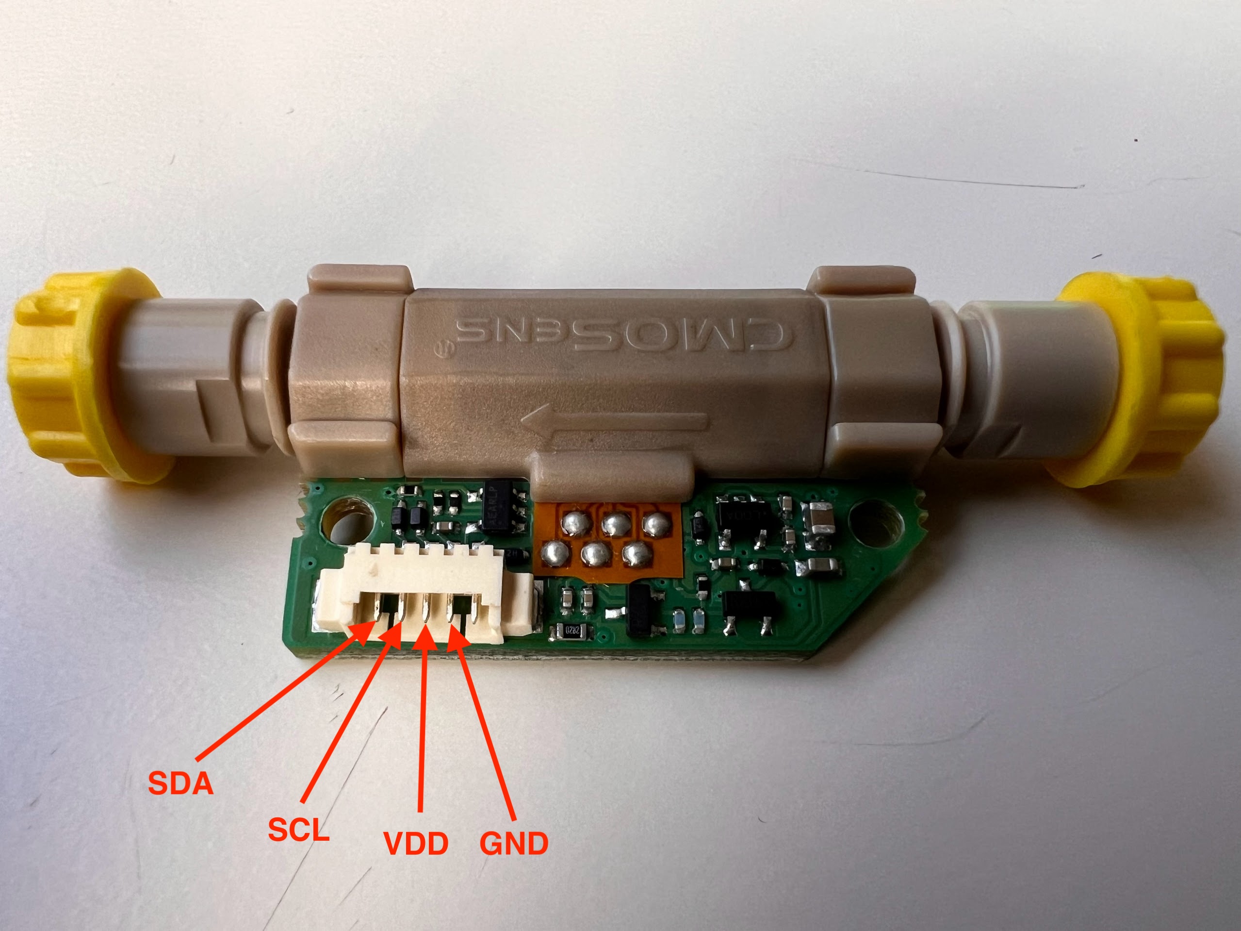
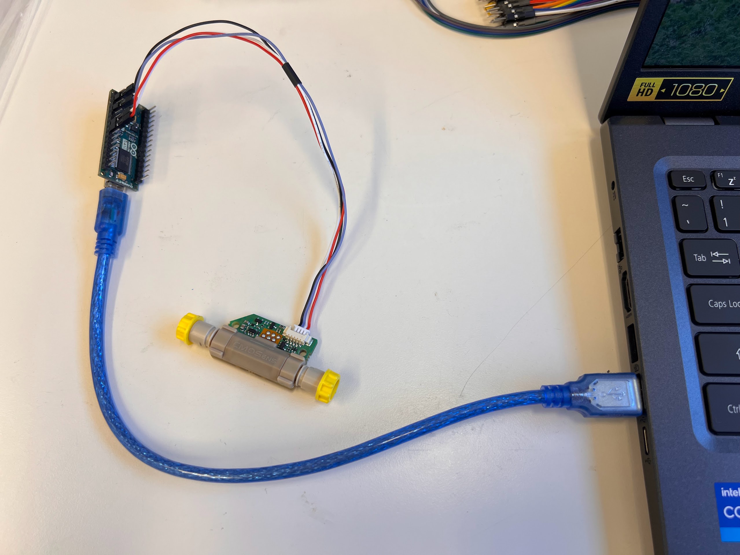
  • The Sensirion LG16-1000D Flow Sensor tells us Flow rates in the 0-1000μl range.
  • The Flow Sensor works by measuring heat transfer.
  • This heat transfer can vary depending on the Dissolved Chemicals or Fluid Being used, therefore this sensor needs to be Calibrated before use.
  • We have already calculated some Calibration values for this Sensor but it might be useful to Check the Calibration.
  • We will learn how to check this Calibration in a separate notebook.
  • We use the Sensirion Flow Sensor for the Bead Channel Only.
  • There is a Thin Glass Capillary inside the Flow Sensor, overtightening can cause this to break. Please follow any precautions mentioned in the datasheet.
Location of Flow Sensors in Schematic Location of Sensirion Flow Sensor in Schematic

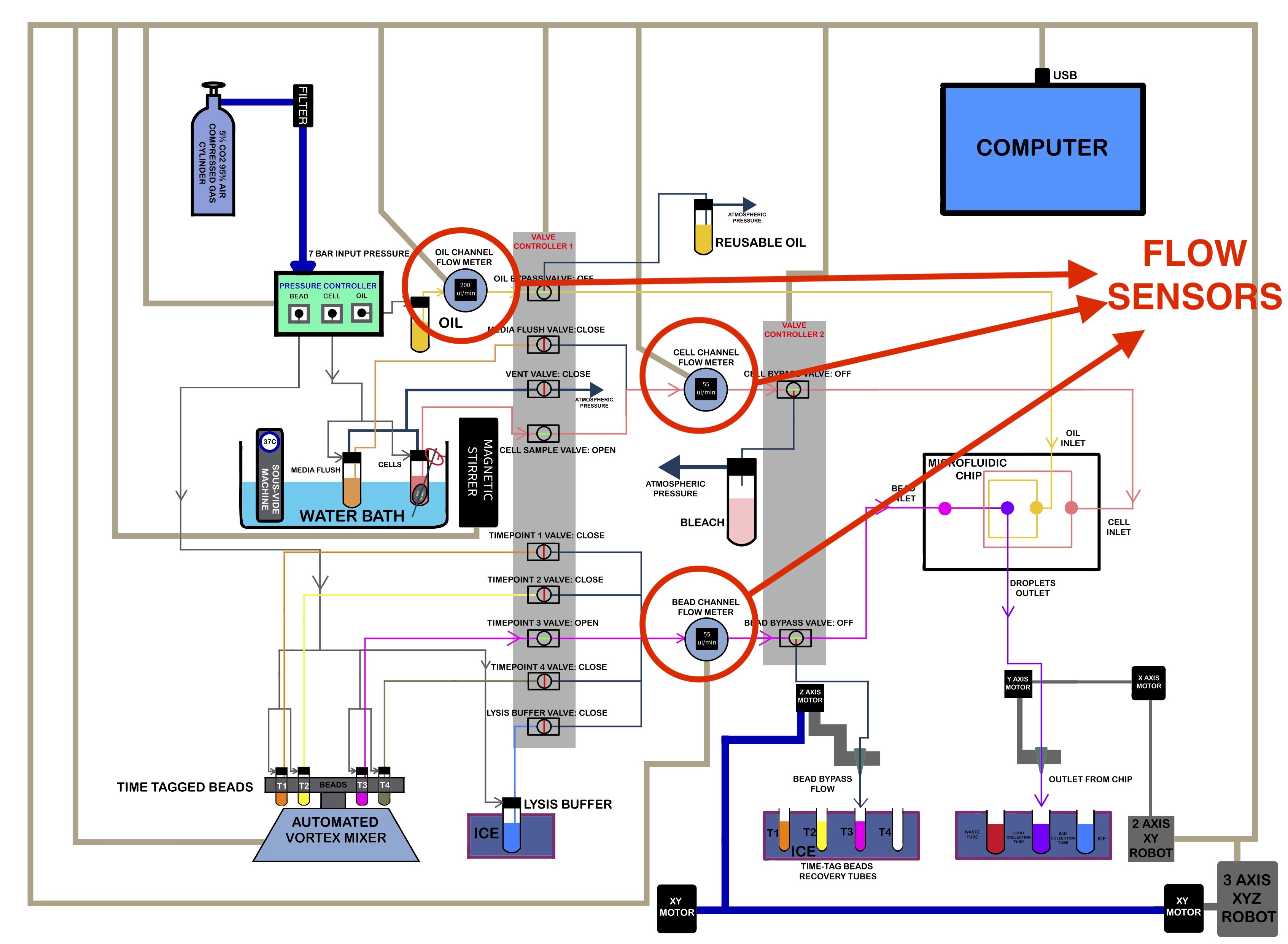
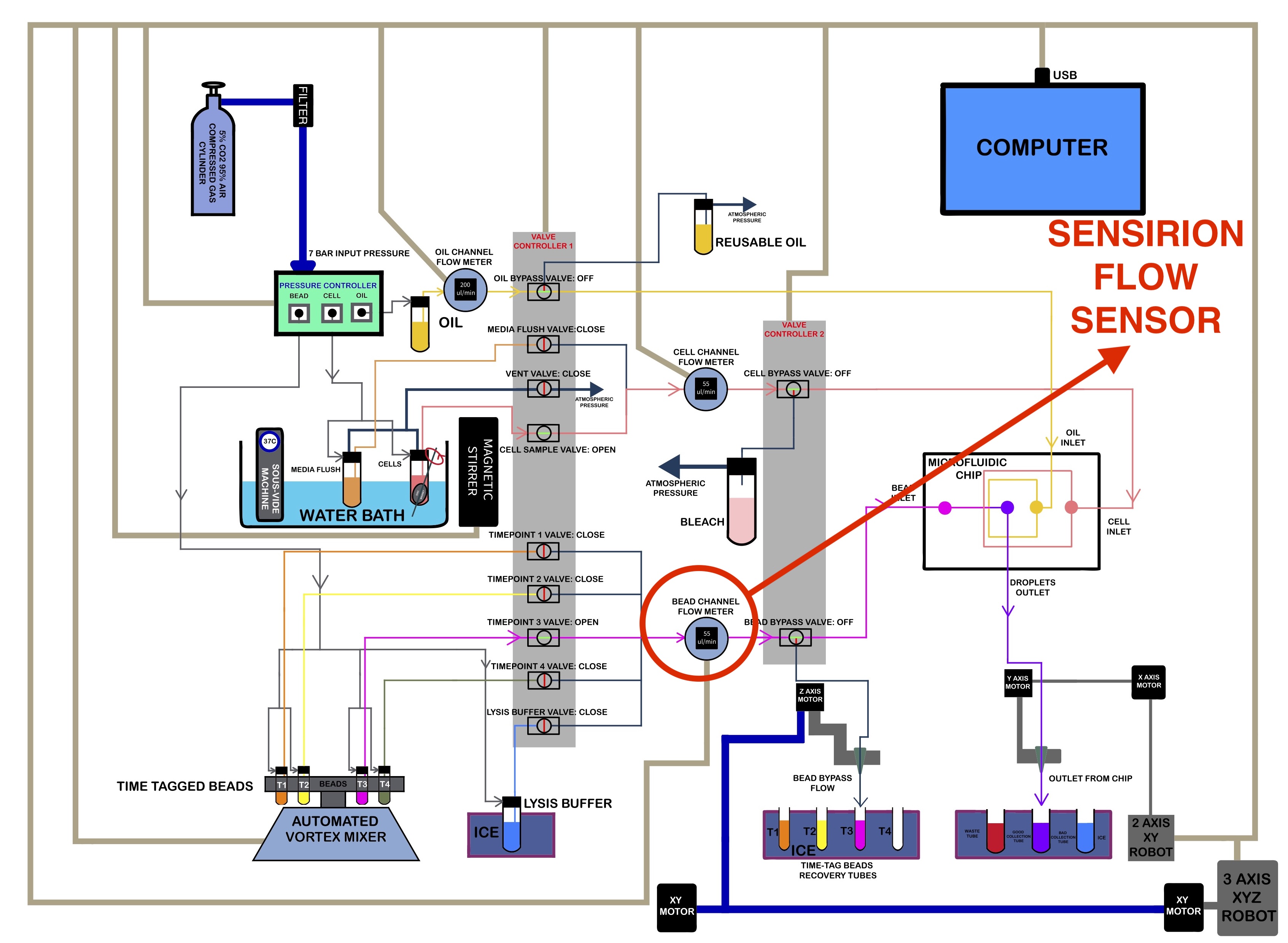
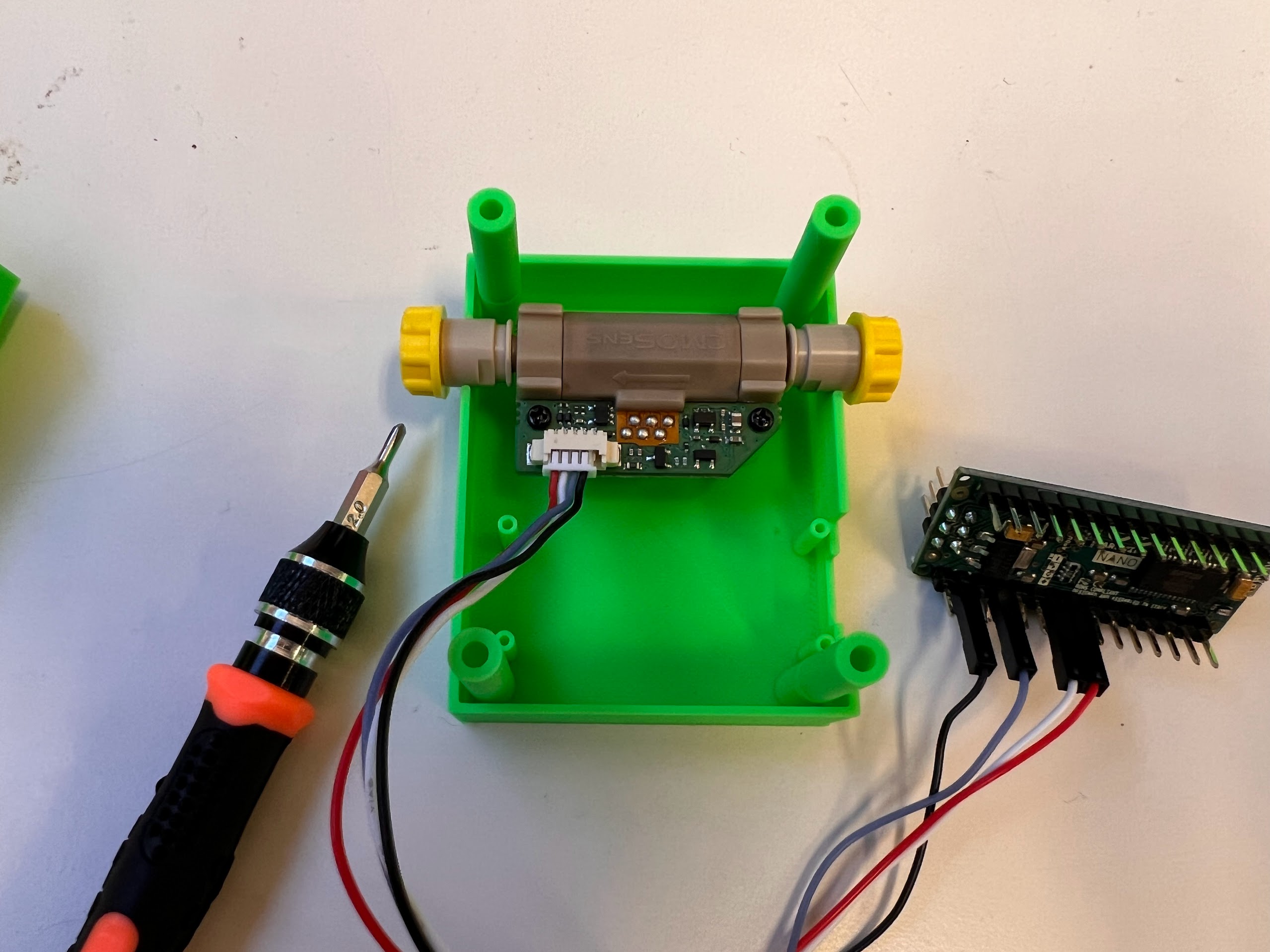
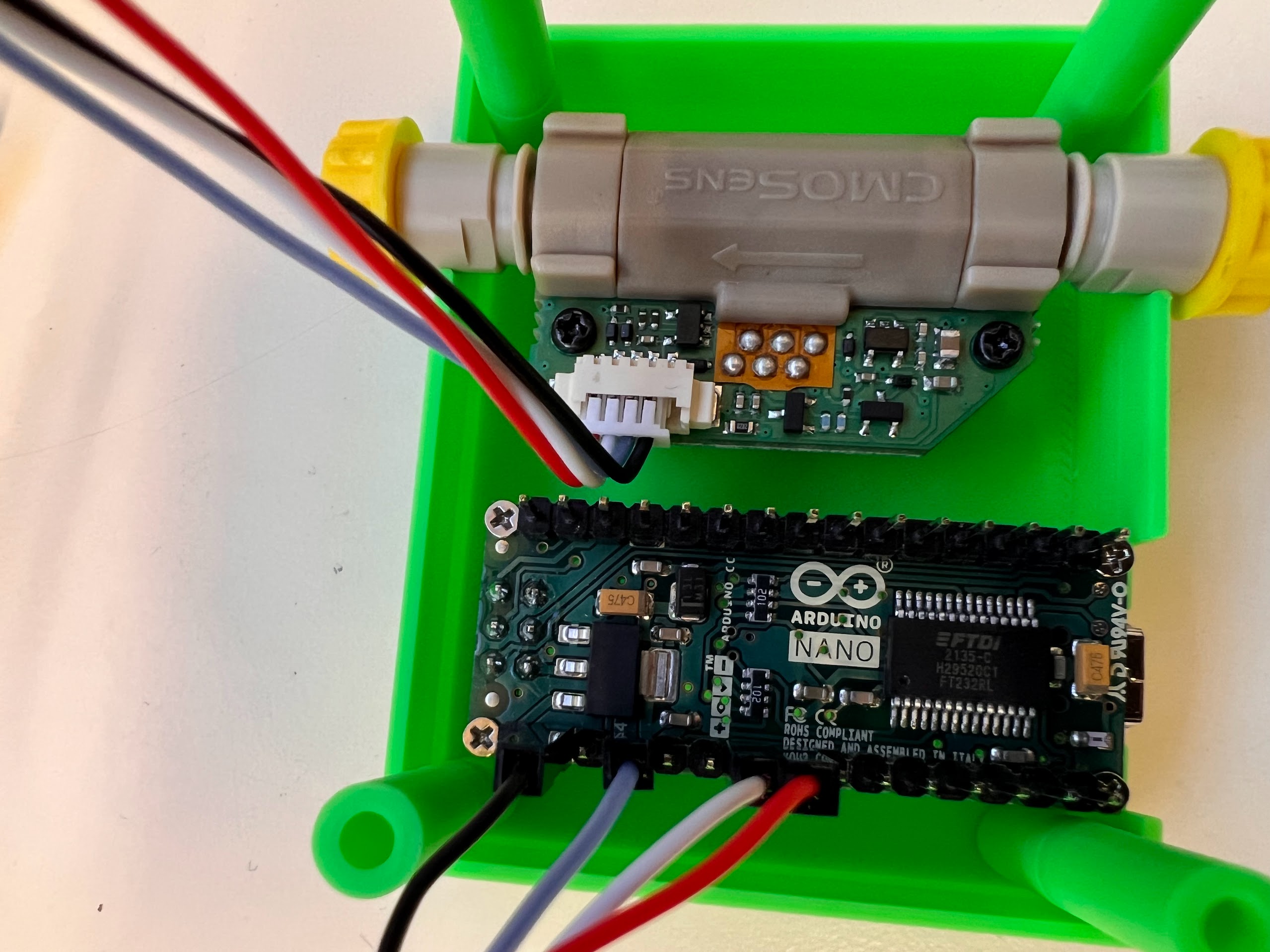
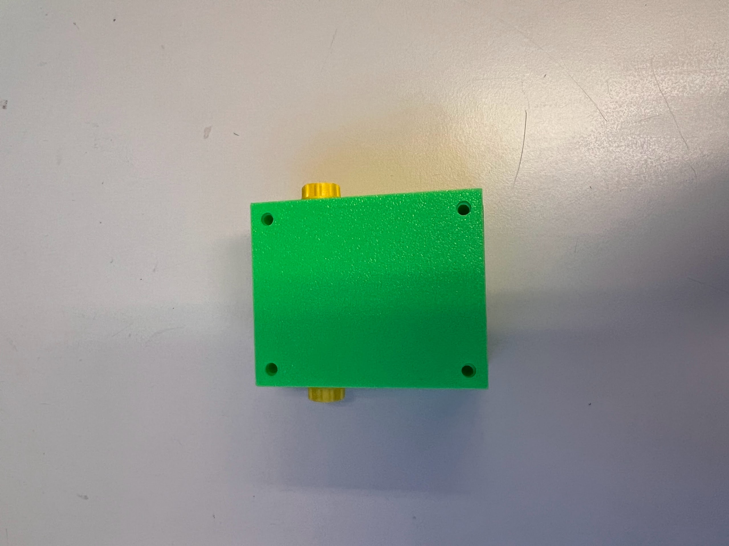
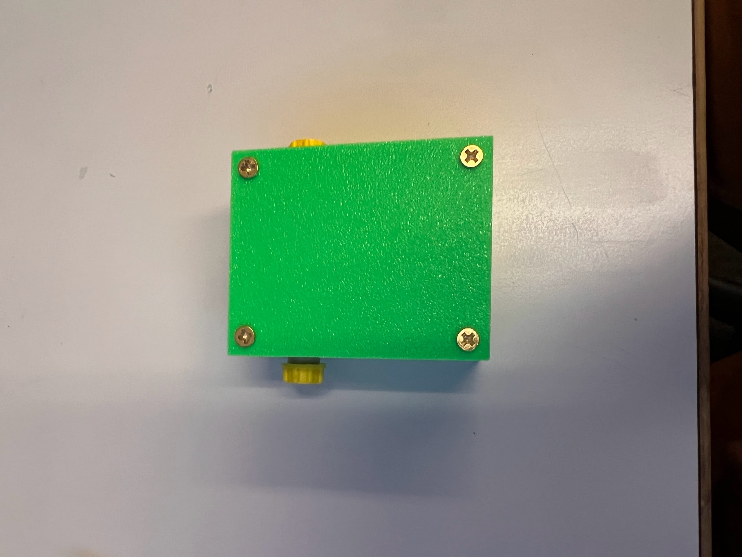
3D Printing Sensor Housing

  • We used a Bambu Lab X1 Carbon to print the Housing.
    • 0.4mm Nozzle
    • Textured PEI Plate
  • We generated a 3MF File with all the Settings we used for the Print. You can open this file on the Orca Slicer.
  • The Original STEP Files and F3D Files can be found in this directory.
  • We recommend getting a 3D Printing Accessories Kit if you haven't purchased one already.
    • Its extremely helpful in removing supports and cleaning up the print.
  • You can watch the Timelapse Video Below:
In [1]:
%%HTML
<video width="800" height="600" controls>
  <source src="img/video_2024-07-26_07-01-26.mp4" type="video/mp4">
</video>

Ordering the Parts

  • You can order the LG16-1000D Flow Sensor from either Digikey or Mouser.
    • We Payed 500$ Before Tax in May 2024 through University of California Negotiated Pricing on Digikey.
  • Mini Self Threading Screws.
    • We used the M2 5mm Screws and M1.64 3.74mm Screws
  • M3 Self Tapping Screw set.
    • We used the M3 8mm Screws
  • An Electronics Screwdriver set.
  • Arduino Nano
  • Molex PicoBlade 1.25 to Dupont 2.54mm Jumper Adapter Cables
  • USB A to Mini USB B Cable

Wiring and Uploading Sketch

  • As mentioned in the Datasheet, the LG16-1000D Flow Sensor uses the I2C Communication Protocol to Send Data.
  • We can use an Arduino Nano Microcontroller to read this data and then send it to our Computer via USB.
  • According to the Datasheet there are 4 Active Pins on the Sensor and 1 which is not in use. The active pins are:
    • SDA: This pin is used for Sending and Receiving Data.
    • SCL: Clock pin, used for sending the clock signal for Synchronizing the Arduino and Sensor.
    • VDD: +5V DC Input Pin.
    • GND: Ground Pin.
Labeled Image of Sensor with Pins Labeled Pinout Diagram in Datasheet
  • According to the Arduino I2C Documentation:
    • A4 Pin is Default for SDA on the Nano.
    • A5 Pin is Default for SCL on the Nano.
  • Using a 4 Pin Molex to Female Dupon Jumper Cable:
    • Connect the SDA (Red)Jumper to the A4 Pin on the Arduino.
    • Connect the SCL (White)Jumper to the A5 Pin on the Arduino.
    • Connect the VDD (Blue)Jumper to the 5V Pin on the Arduino.
    • Connect the GND (Black)Jumper to the GND Pin on the Arduino.
Connect the Arduino to the Sensor A4 is for SDA and A5 is for SCL
  • Connect your Arduino Nano to your Computer using a USB Mini B to USB A Cable.
  • We have forked the Sensirion Arduino Library and made some modifications to easily get the data from the Sensor.
  • Open the Example 03 Sketch in the Arduino IDE and upload it to your Arduino Nano.
  • Execute the Cell Below to Watch a Video of the Process.
In [2]:
%%HTML
<iframe width="800" height="600" src="https://www.youtube.com/embed/uNjWOinYsms?si=XAR_2zqnOr8F-Ozr" title="YouTube video player" frameborder="0" allow="accelerometer; autoplay; clipboard-write; encrypted-media; gyroscope; picture-in-picture; web-share" referrerpolicy="strict-origin-when-cross-origin" allowfullscreen></iframe>

Assembling the Housing

  • Using the 2mm Phillips Head (PH00):
    • Screw Two M2 5mm Self Threading Screws into the Sensor mounting holes to secure it to the Bottom Housing.
    • Screw Four M1.64 3.74mm Screws into the Arduino Nano mounting holes to secure it to the Bottom Housing.
  • Place the loose wires inside the Bottom Housing and Place the Top Housing on the Bottom Housing.
    • Make sure the wires don't obstruct the Top housing from Sitting flat against the Bottom Housing.
  • Using the 3mm Phillips Head (PH0):
    • Screw Four M3 8mm Self Threading Screws into the Top Housing to secure it to the Bottom Housing.
  • Execute the Cell Below to Watch a Video of what the final product looks like:
In [3]:
%%HTML
<iframe width="800" height="600" src="https://www.youtube.com/embed/HiPDJiEU-a0?si=lQvxD__1ARV8tmb3" title="YouTube video player" frameborder="0" allow="accelerometer; autoplay; clipboard-write; encrypted-media; gyroscope; picture-in-picture; web-share" referrerpolicy="strict-origin-when-cross-origin" allowfullscreen></iframe>
  • Execute the Cell Below to Watch a Video of what the final product looks like without the Protective nuts blocking the ports.
In [4]:
%%HTML
<iframe width="800" height="600" src="https://www.youtube.com/embed/Zoi-bUeLWCg?si=Zvi9YNC_1nitU7VC" title="YouTube video player" frameborder="0" allow="accelerometer; autoplay; clipboard-write; encrypted-media; gyroscope; picture-in-picture; web-share" referrerpolicy="strict-origin-when-cross-origin" allowfullscreen></iframe>

Getting the Sensor Data using Python in Jupyter Notebooks

  • Put the Protective Caps Back on and Connect your Flow Sensor Via USB to your Computer.
  • You can Identify the COM Port by Connecting and then Disconnecting the Controller and then checking which new COM Port Shows up in Arduino IDE.
    • In our case we can see the Port is COM7
  • Close the Arduino IDE. Closing the IDE Severs the Connection to the Sensor. Only one program can connect to the Sensor at a Time.
  • We will now Connect to the Sensor using PySerial.
In [5]:
import serial
import time
arduinoSensirionFlowMeterCOM="COM7"

arduino_Bead_Flow_meter = serial.Serial(arduinoSensirionFlowMeterCOM, timeout=1, write_timeout=1) 
time.sleep(5.0)
print(arduino_Bead_Flow_meter.name)
print(arduino_Bead_Flow_meter.get_settings())
print(arduino_Bead_Flow_meter.is_open)
COM7
{'baudrate': 9600, 'bytesize': 8, 'parity': 'N', 'stopbits': 1, 'xonxoff': False, 'dsrdtr': False, 'rtscts': False, 'timeout': 1, 'write_timeout': 1, 'inter_byte_timeout': None}
True
  • Lets define a function that gets the latest flow rate data in μl/min from the flow sensor.
  • Since we have no liquid in the flow sensor this will not be a correct measurement.
  • We will refine this further when we assemble this flow sensor as parts of the whole device.
In [6]:
def get_bead_channel_flowrate():
    #Empty the buffer if its more than 11 bytes so new values can be brought in during sampling.
    #The arduino has been programmed to send a maximum of 10 bytes of data in a line. 
    if arduino_Bead_Flow_meter.inWaiting()>11:
        buffer=arduino_Bead_Flow_meter.read(arduino_Bead_Flow_meter.inWaiting())
    while True:
        try:
            beadChannelFlow=float((arduino_Bead_Flow_meter.readline()).decode("utf-8"))
            break
        except ValueError:
            pass
    return beadChannelFlow
In [7]:
get_bead_channel_flowrate()
Out[7]:
1.97
  • Now that we know we can read values from the flow sensor, lets close the connection to the Sensor after which we are done.
In [8]:
arduino_Bead_Flow_meter.close()