Instructions for Assembling Valve Controller V2

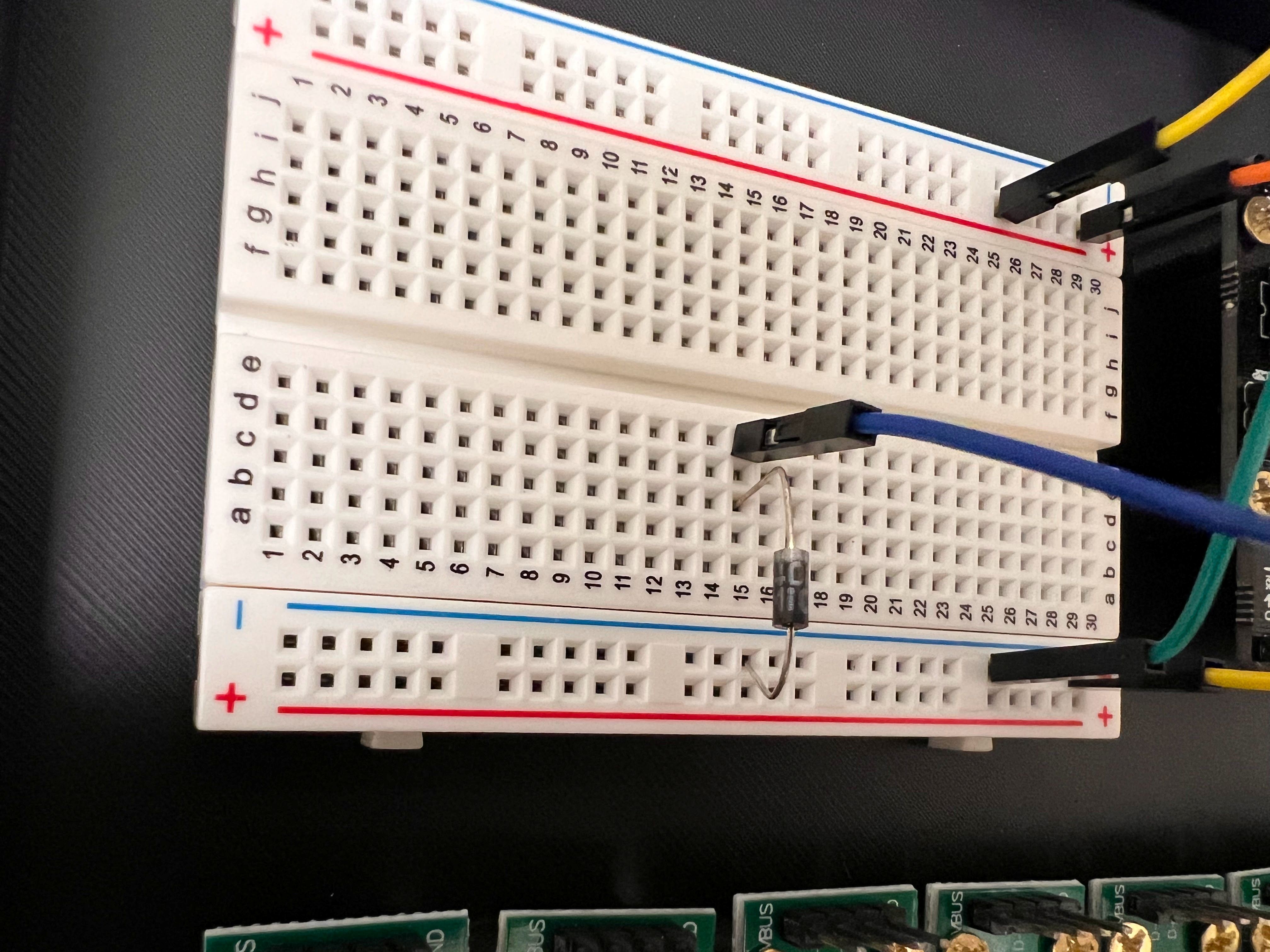
  • We updated the instructions to add a Flyback diode for the Solenoid Valves.

Brief Description of Purpose and Working Principles:

  • We need to a way to control the flow of liquid through the ChronoSeq Device by shutting down or redirecting flow.
  • To help control the flow with our computer we need to build a Valve Controller that can switch specific valves ON or OFF when it receives a command from the computer.
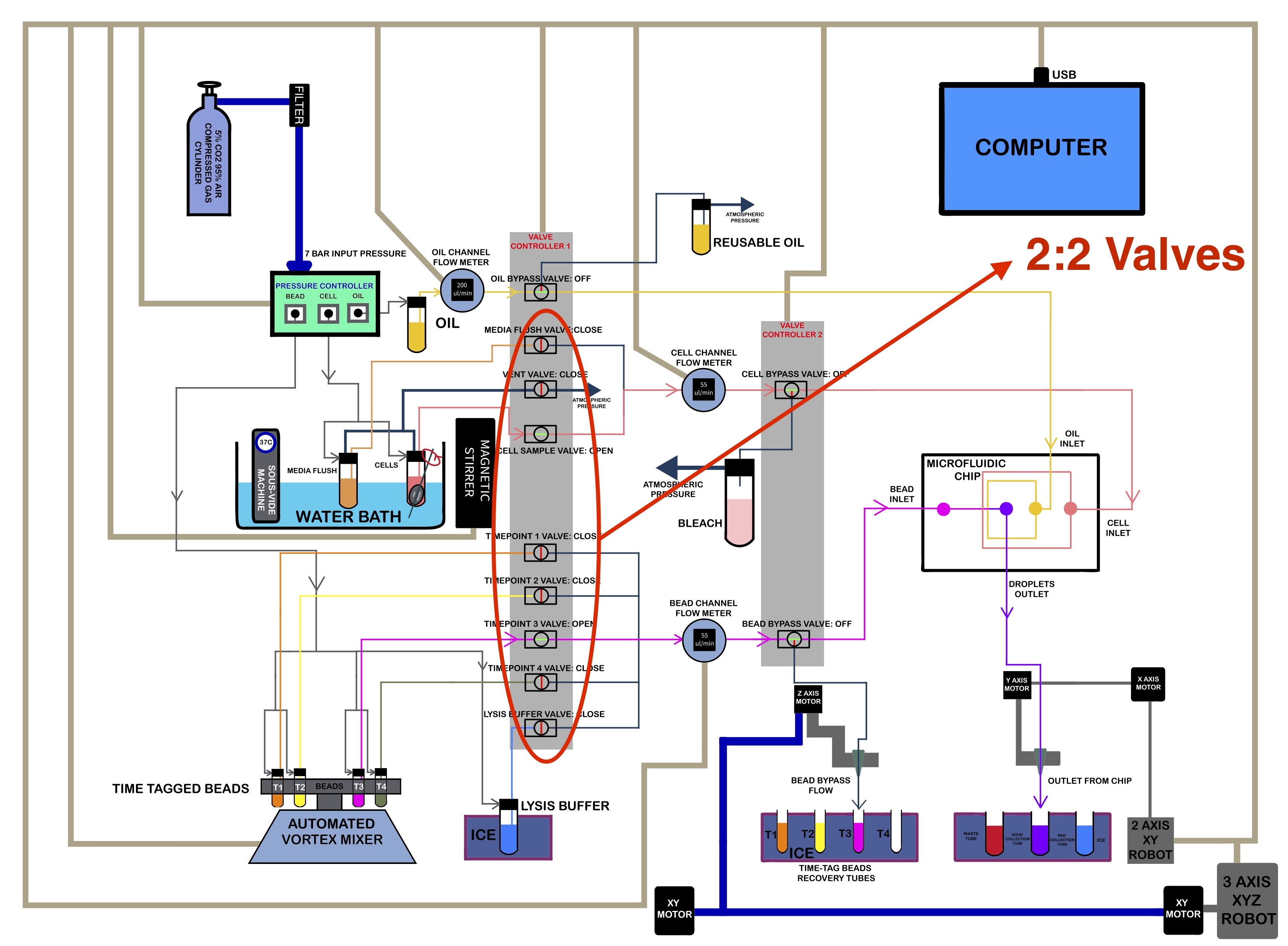
  • The SMC Valves we have selected for our device can be 2:2 Valves or 3:2 Valves.
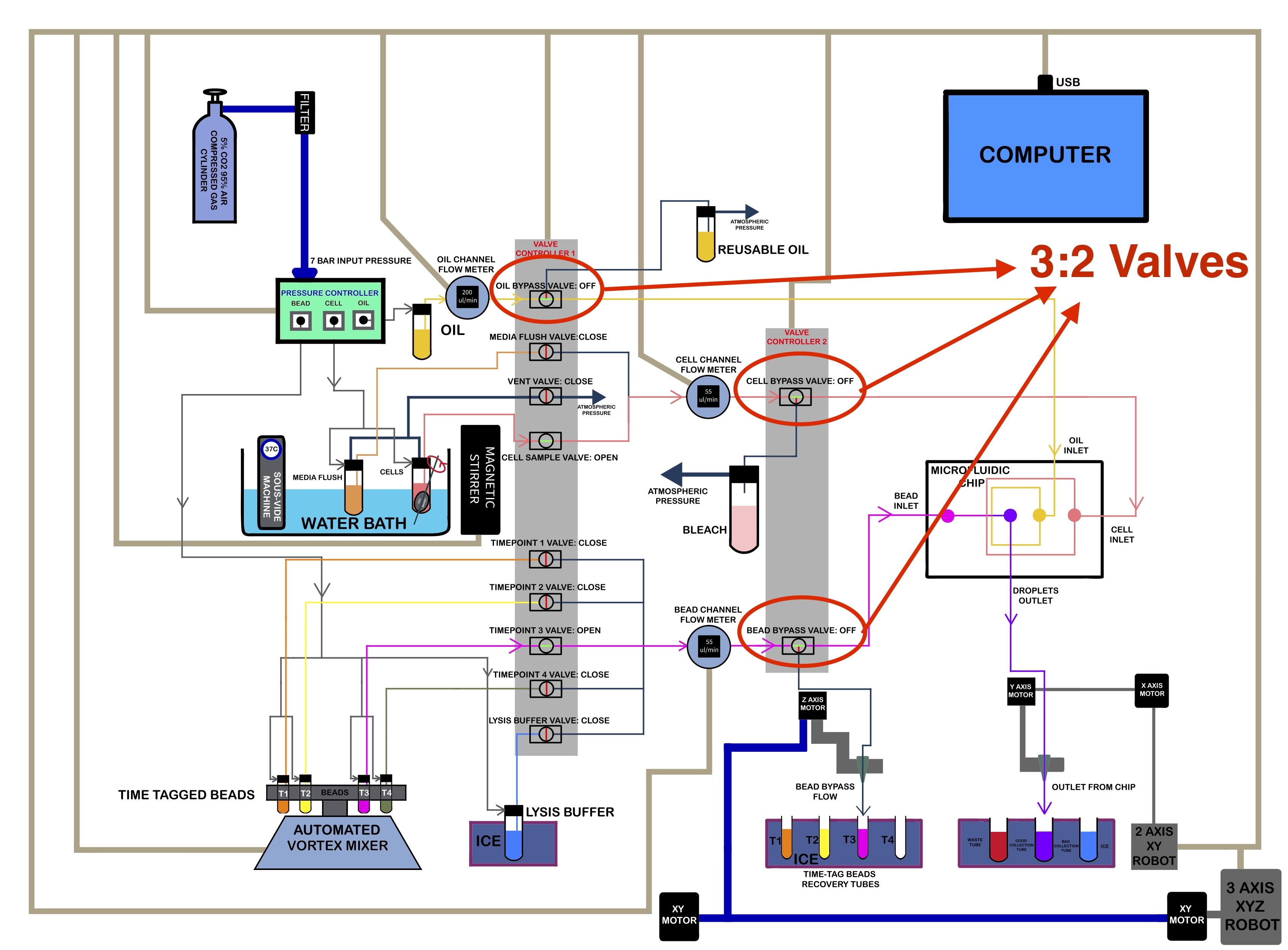
    • 2:2 Valves Turn Flow ON or OFF. Most of these will be used to control flow from Individual Reservoirs.
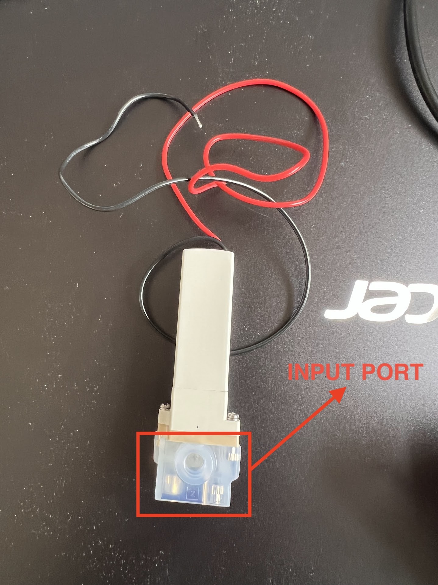
    • 3:2 Valves Redirect Flow from the Input Port to the Main or Bypass Port. We use these as Bypass Valves for Controlling flow into the Microfluidic Chip for each Channel: Cells, Beads and Oil.
  • The 2:2 SMC Valves we have purchased are Normally Closed (NC). Meaning liquid will only flow through them when they are powered ON.
  • The 3:2 Valves allow flow from:
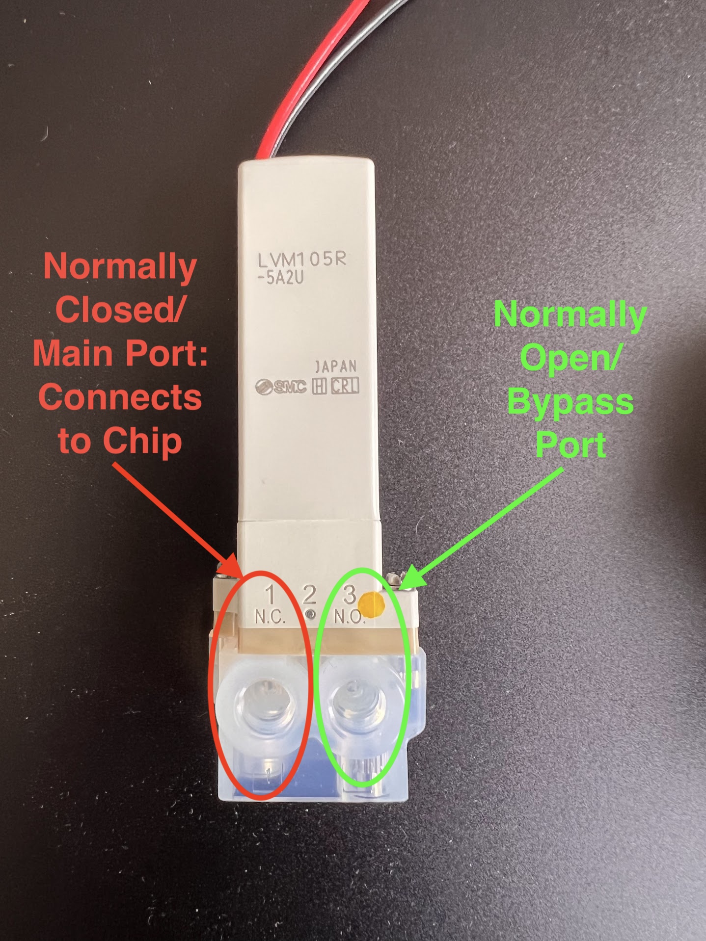
    • The Input Port to the Bypass port when powered OFF. The Bypass port is therefore called the Normally Open (NO) Port.
    • You can identify the NO Port by Looking for the NO Symbol on the Valve near the Port.
    • The Valve allows flow from the Input port to the Main port only when powered ON. This port is therefore called the Normally Closed (NC) Port.
    • You can identify the NC Port by Looking for the NC Symbol on the Valve near the Port.
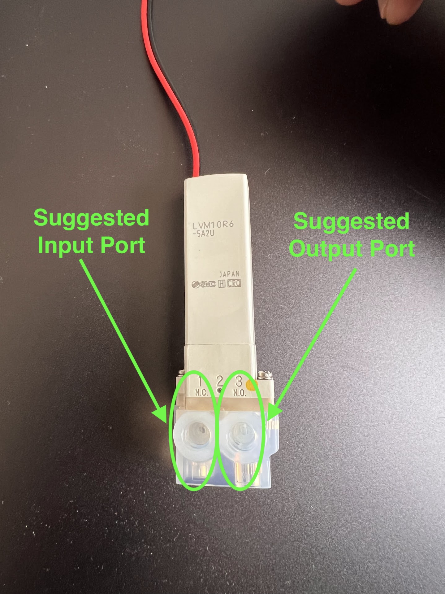
    • The 3:2 Valves can be converted into 2:2 NC or 2:2 NO Valves by blocking either the NC or NO Port using a Delrin Plug.
3:2 Valve Input Port 3:2 NC and NO Port Locations 2:2 Valve Suggested Input and Output Ports
Location of 3:2 Bypass Valves in Schematic Location of 2:2 Valves in Schematic

Ordering Information for SMC Valves

  • SMC Valves are Highly Configurable and the exact product number represents this configuration.
    • For Example this website allows you to generate a product number before ordering.
    • Make sure the Chemicals being used for your application are compatible with the Wetted materials in your Valve Configuration.
  • We will be ordering the LVM10 Series of Valves.
  • The Following product numbers and Quantities were ordered for the two types for Valves:
    • 2:2 Valves: LVM10R6-5A2U . Quantity : 30 Units
      • 22 Units are needed in the Version of the ChronoSeq Device with 16 Timepoint Reservoirs.
      • The remaining 8 were kept as backup replacements.
      • You can order only 22 Valves if you want to save some money.
      • Only 18 Valves are necessary if your device has 12 Timepoint Reservoirs.
    • 3:2 Valves: LVM105R-5A2U . Quantity : 5 Units
      • 3 Units are needed in the Current Version of the ChronoSeq Device.
      • The remaining 2 were kept as backup replacements.
      • You can order only 3 Valves if you want to save some money.
  • SMC has many global suppliers and your local supplier might vary.
    • Different suppliers offer different prices.
    • Its best to find the most competitive local supplier for your area.
    • You can use this website to help you locate a supplier.
  • We ordered our valves from Bay Advanced Technologies located in Orange County, CA.
    • Its best to call them to place an order. Their number is +1 714-241-1031 .
    • You should also email Monica(mgparra@bayat.com) or Derek(dloe@bayat.com) if they still work there.
    • You can also call (+1 213-476-3863) or email Colby(cchristy@bayat.com), a local account Manager in San Diego.
    • We payed by providing our Credit Card Number over the phone.
    • Both the 3:2 and 2:2 Valves Cost 81.60USD Each in April 2024.

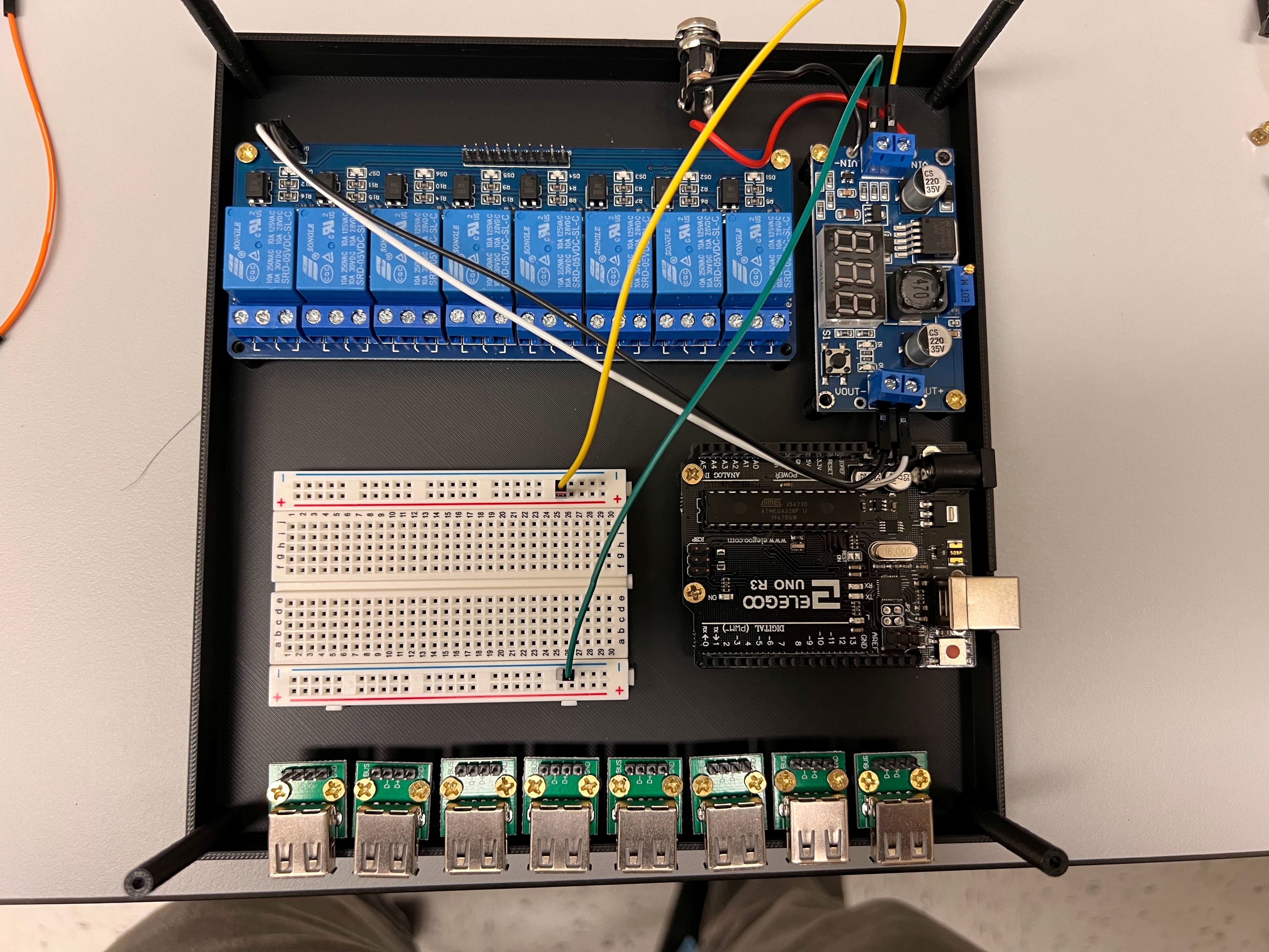
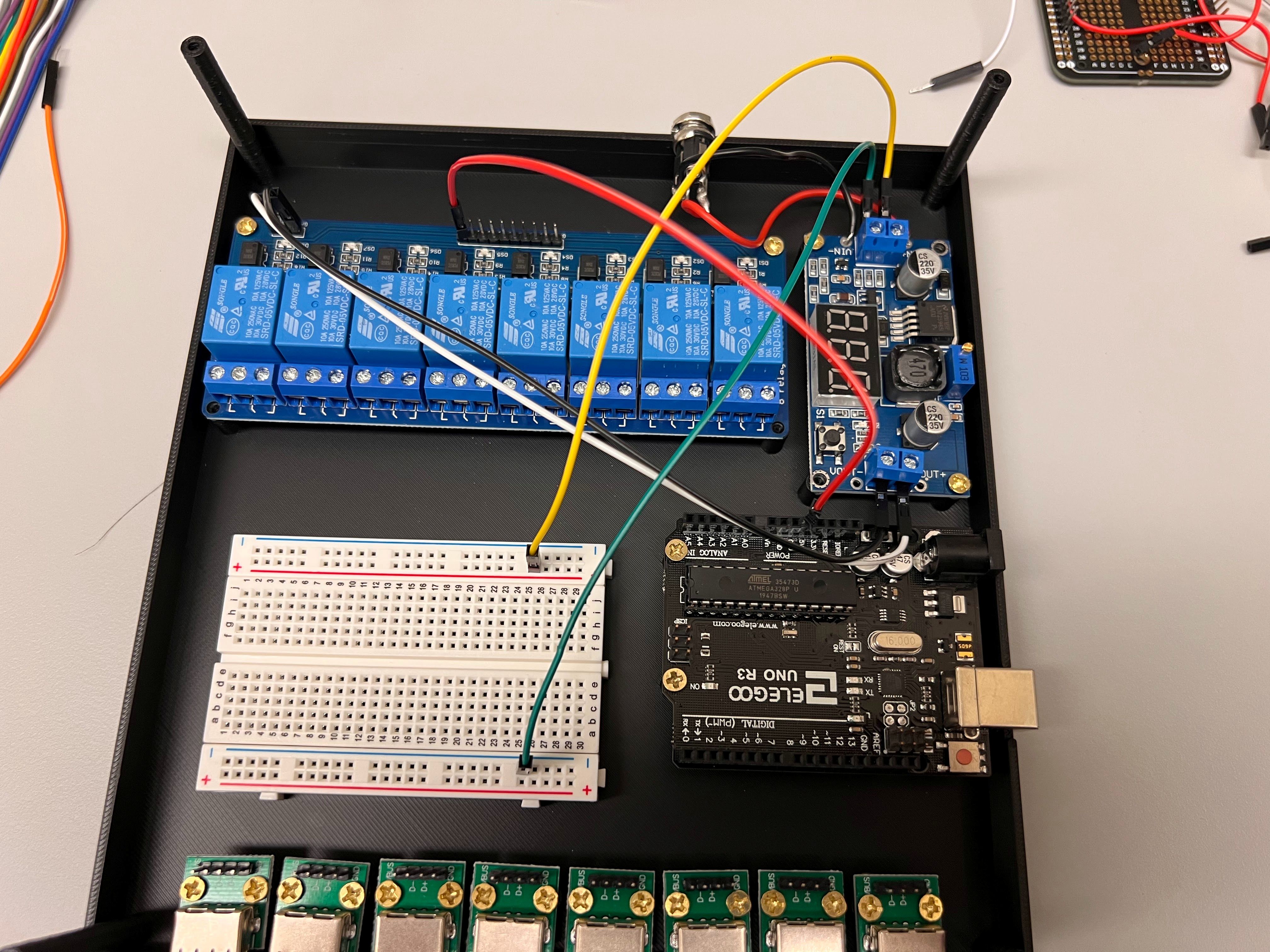
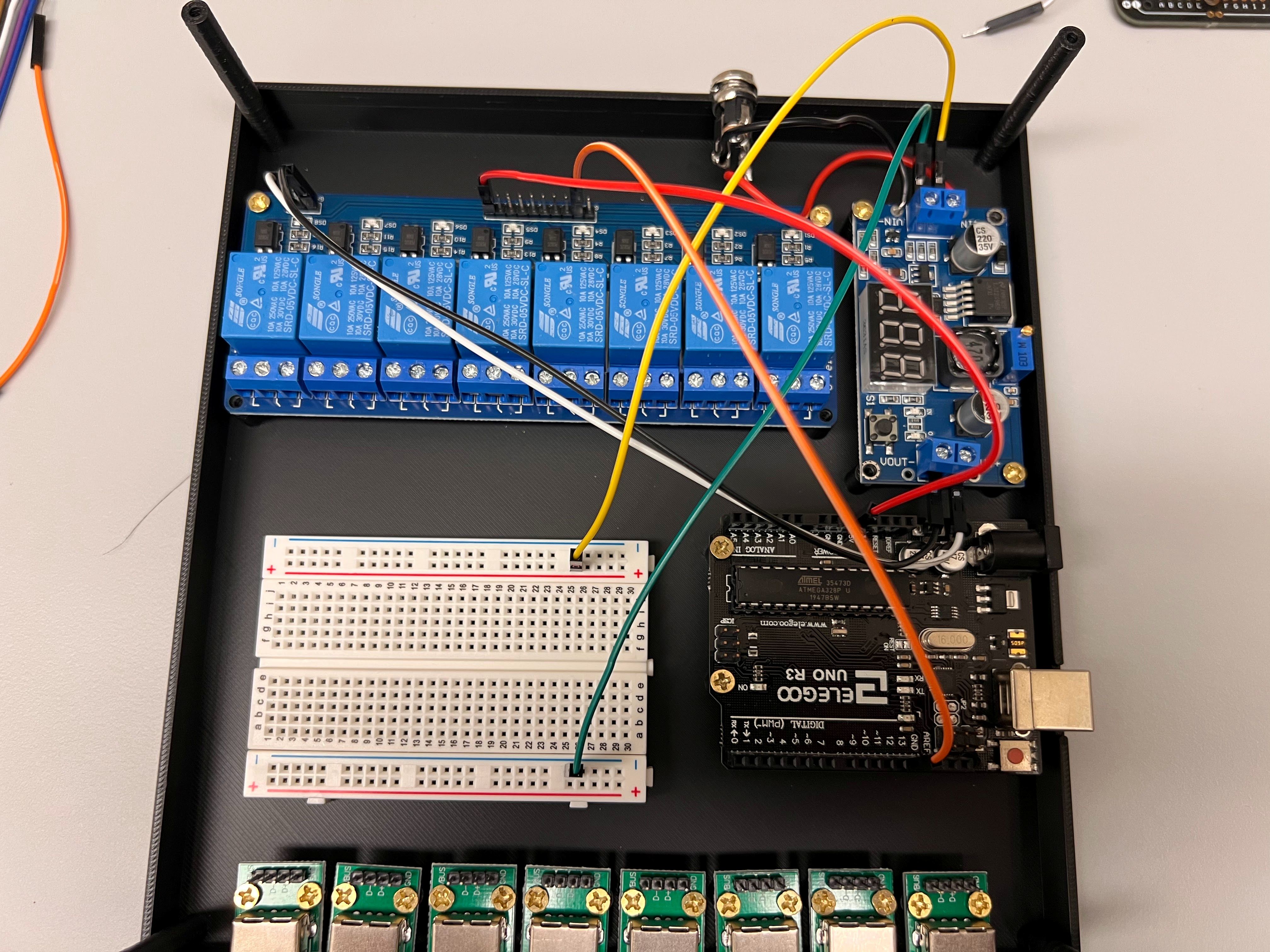
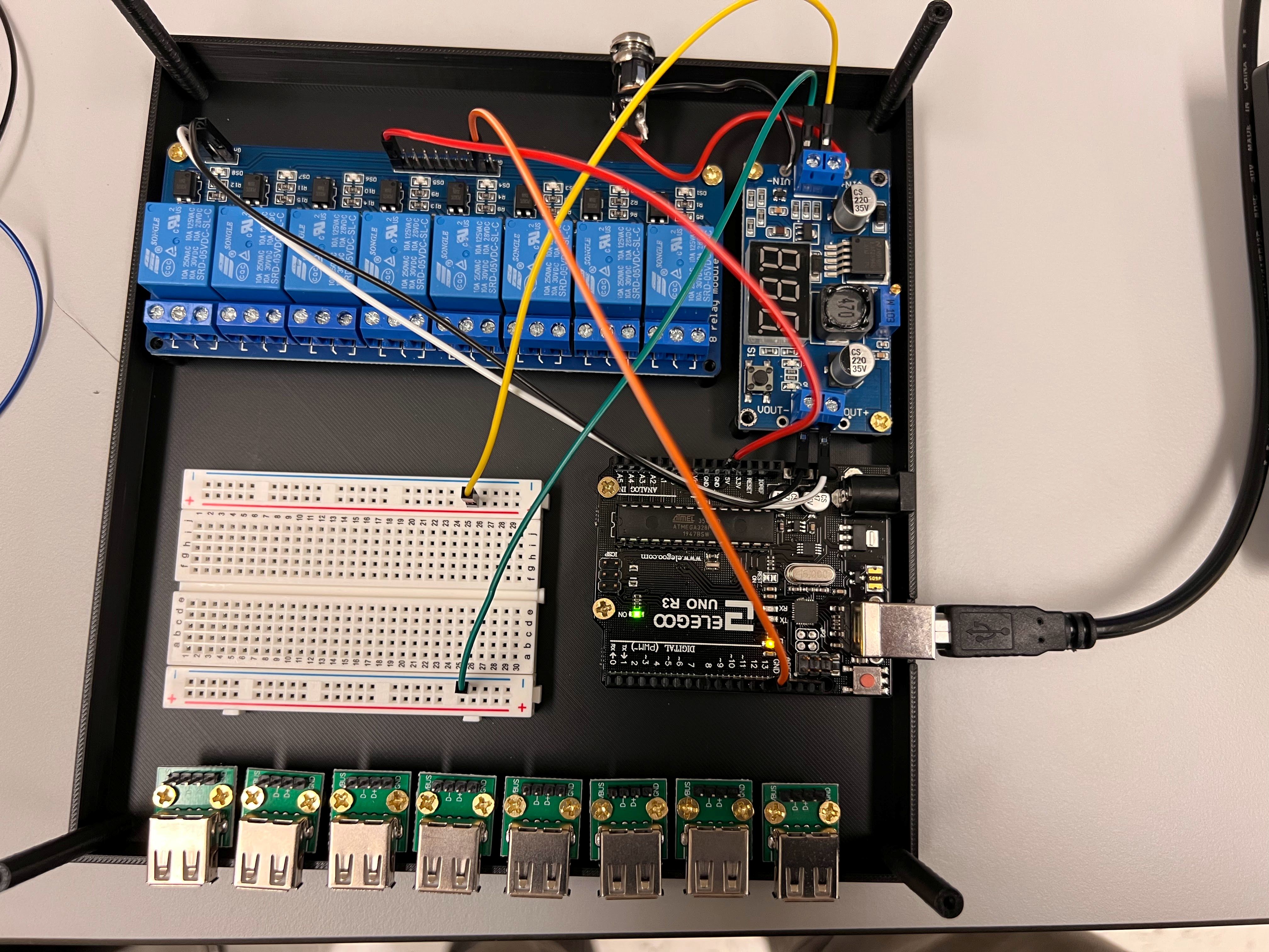
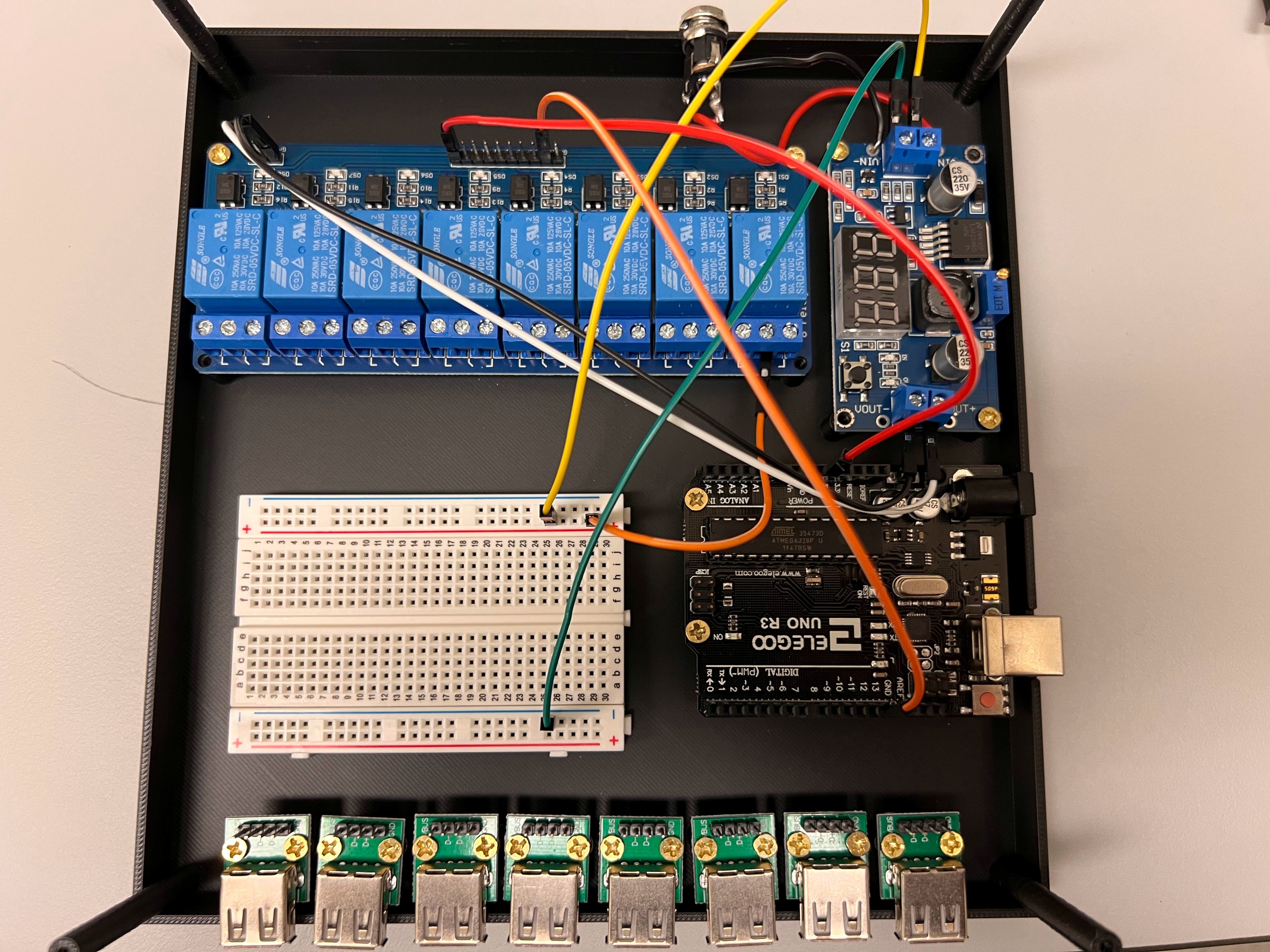
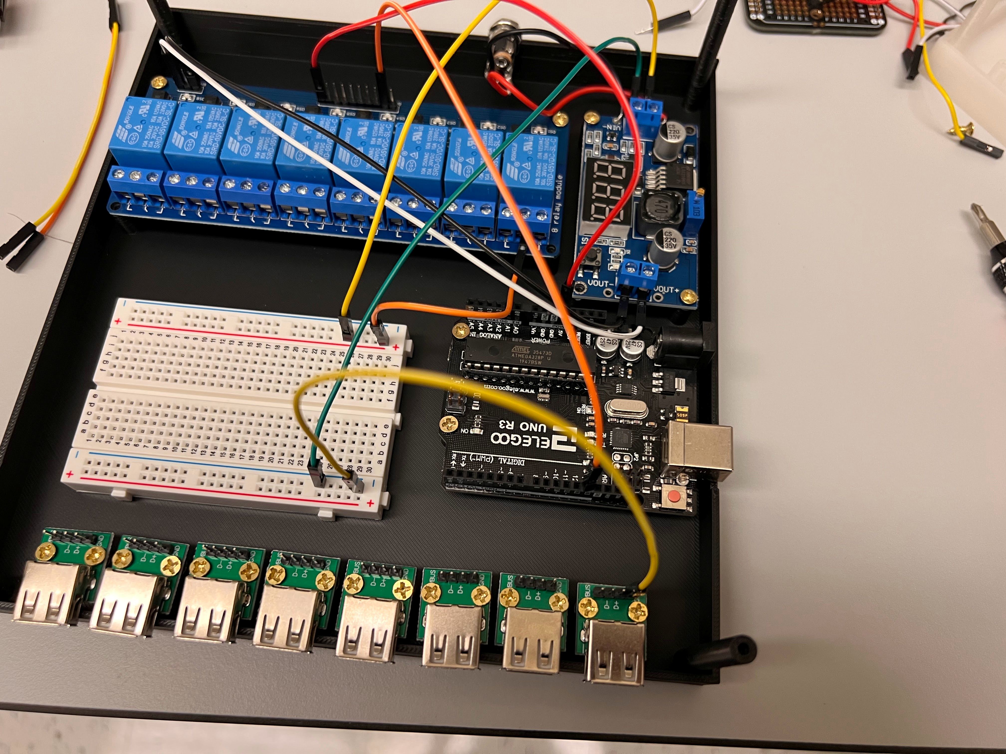
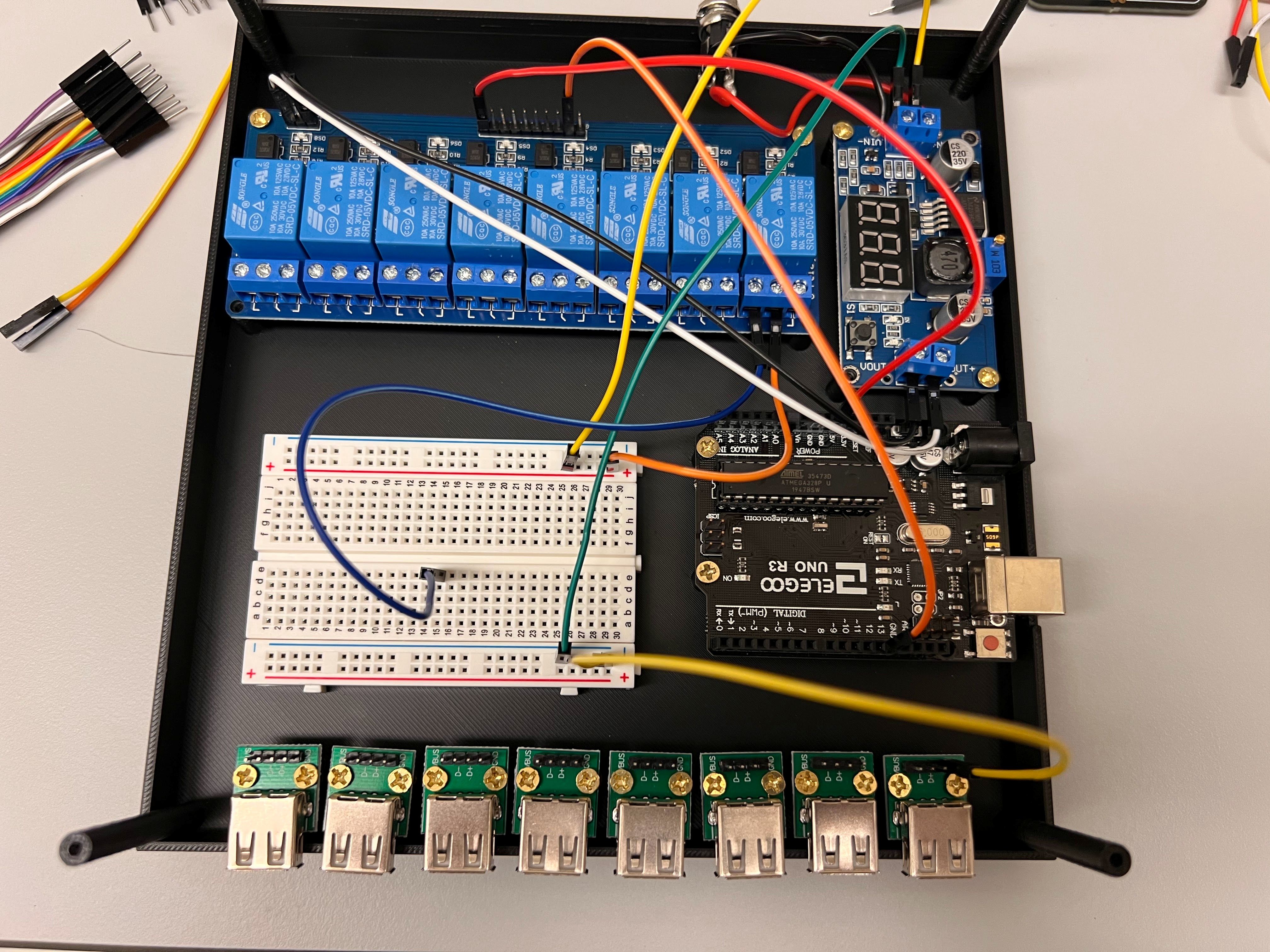
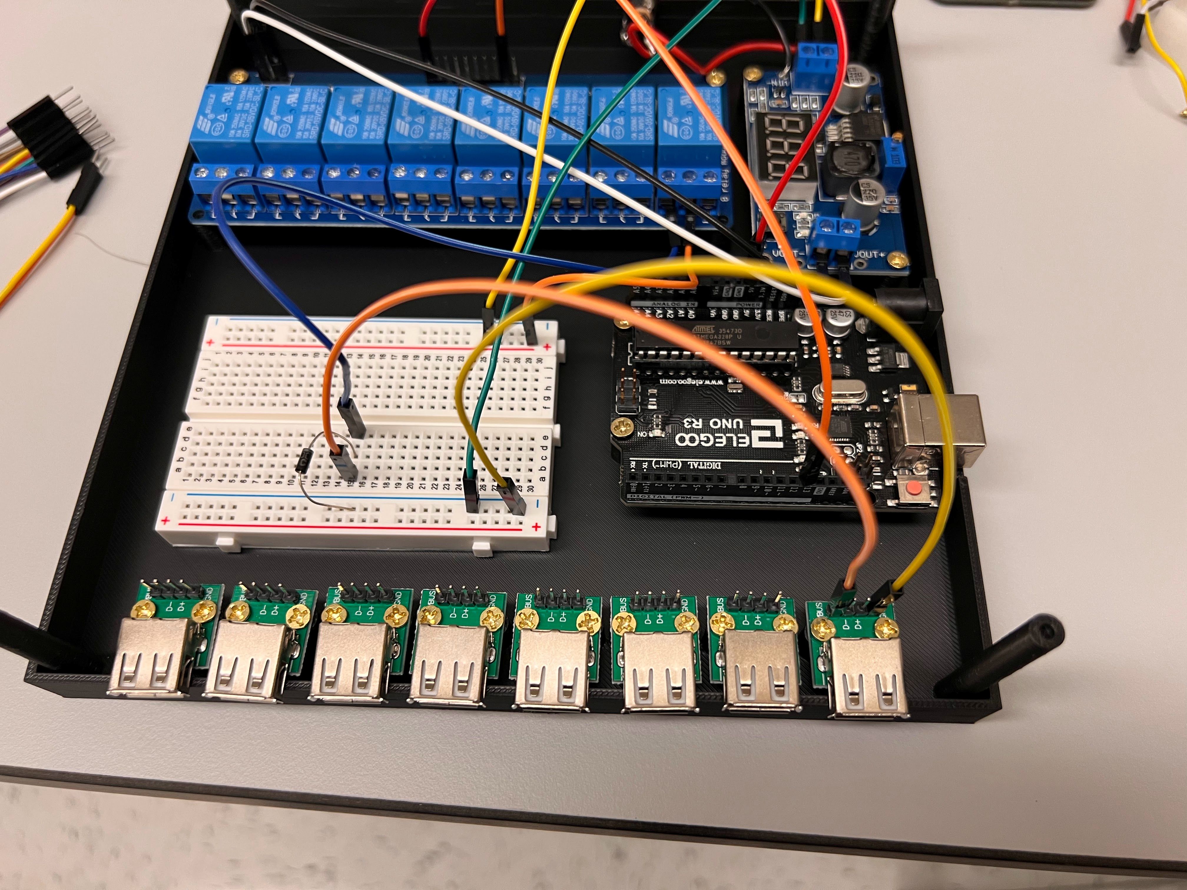
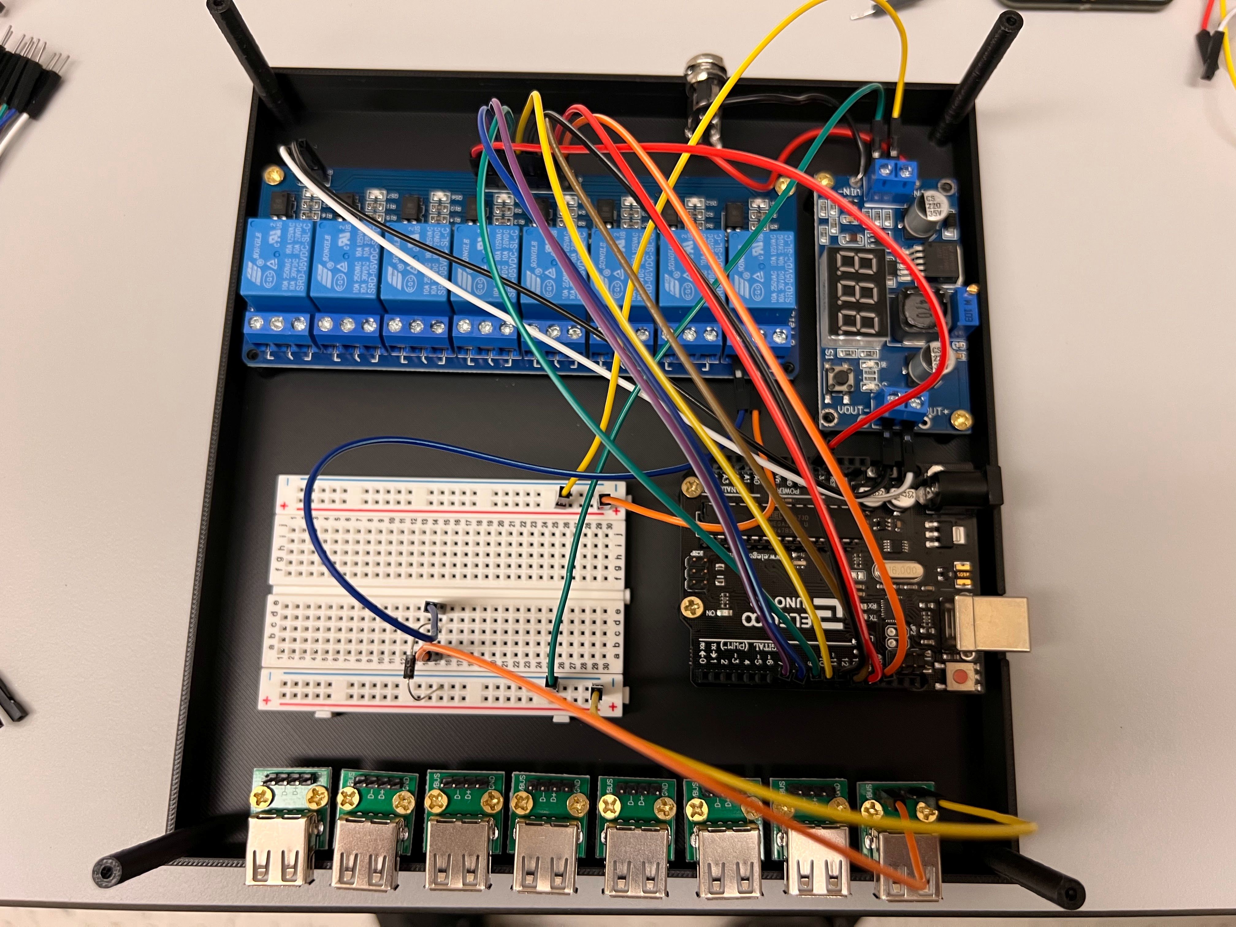
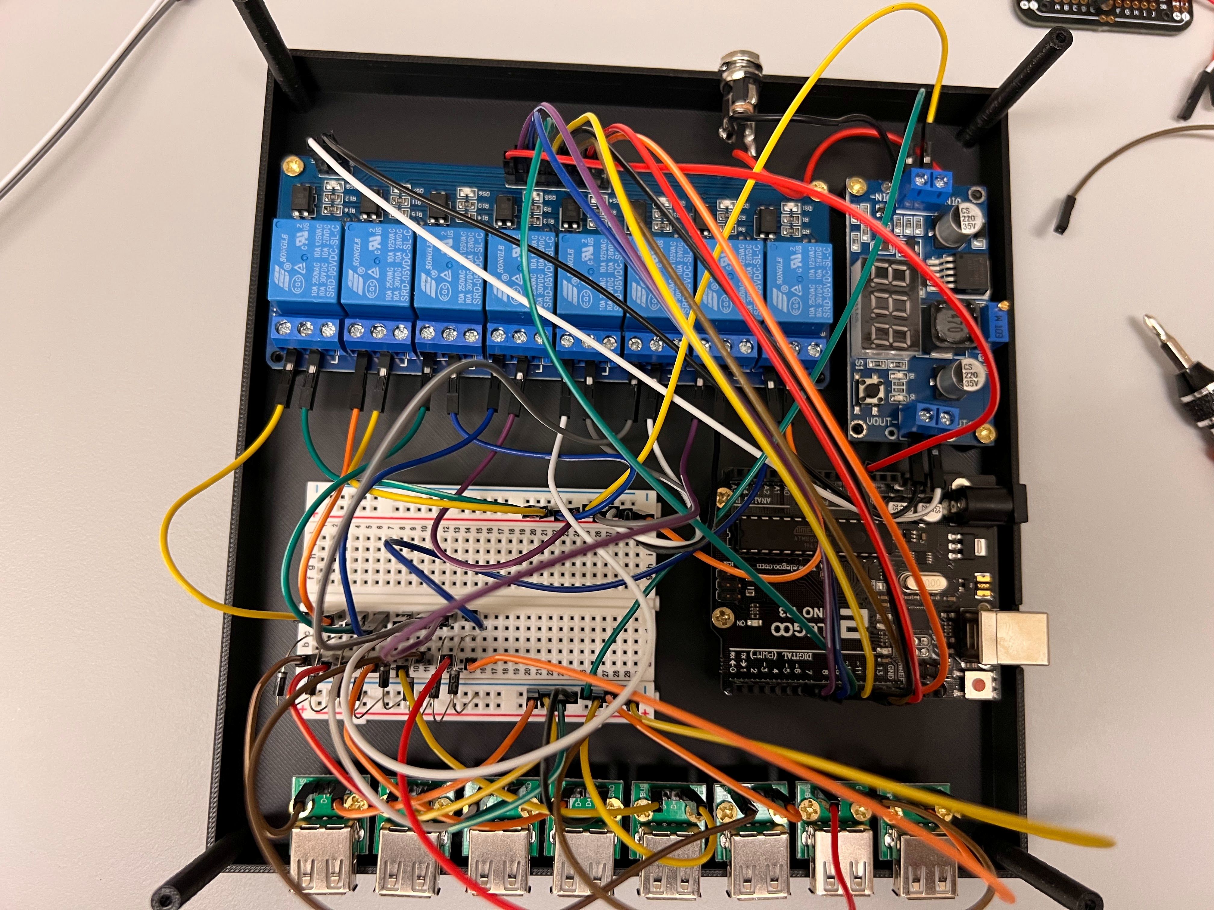
Overview of Valve Controller Design

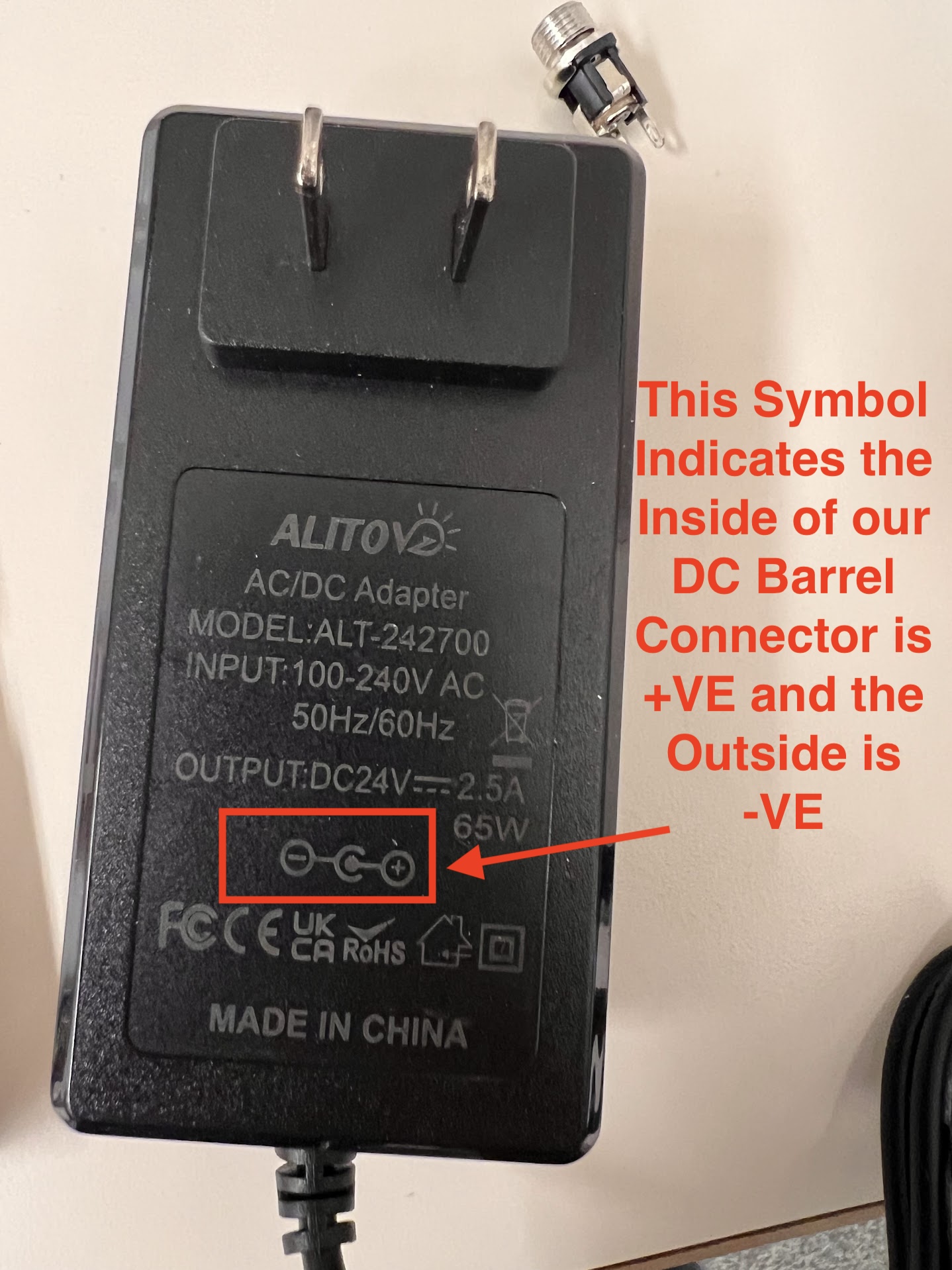
  • Both Valves require 24V DC Current to Turn ON and Consume about 1.5W of Power or 60mA of Current.
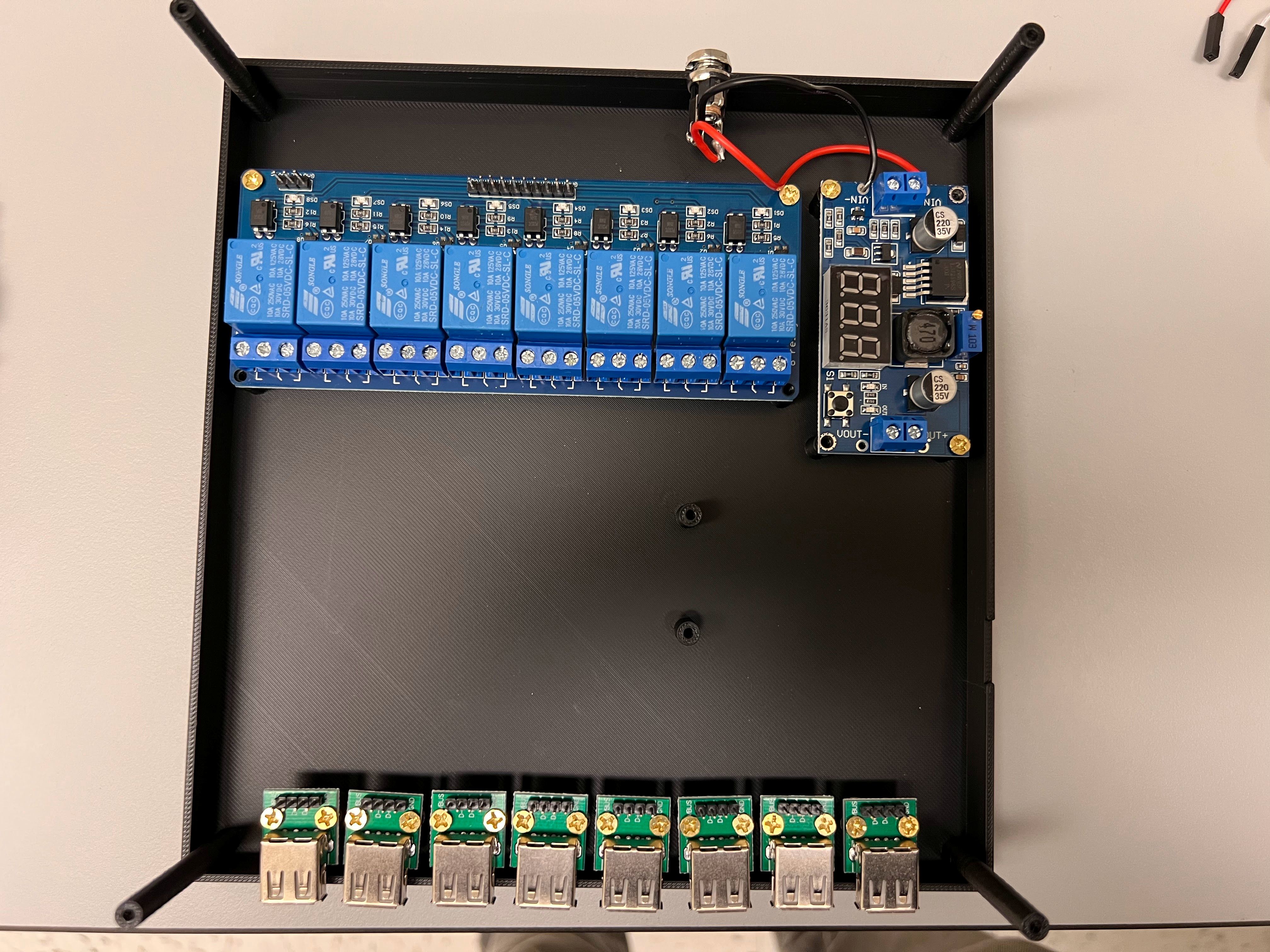
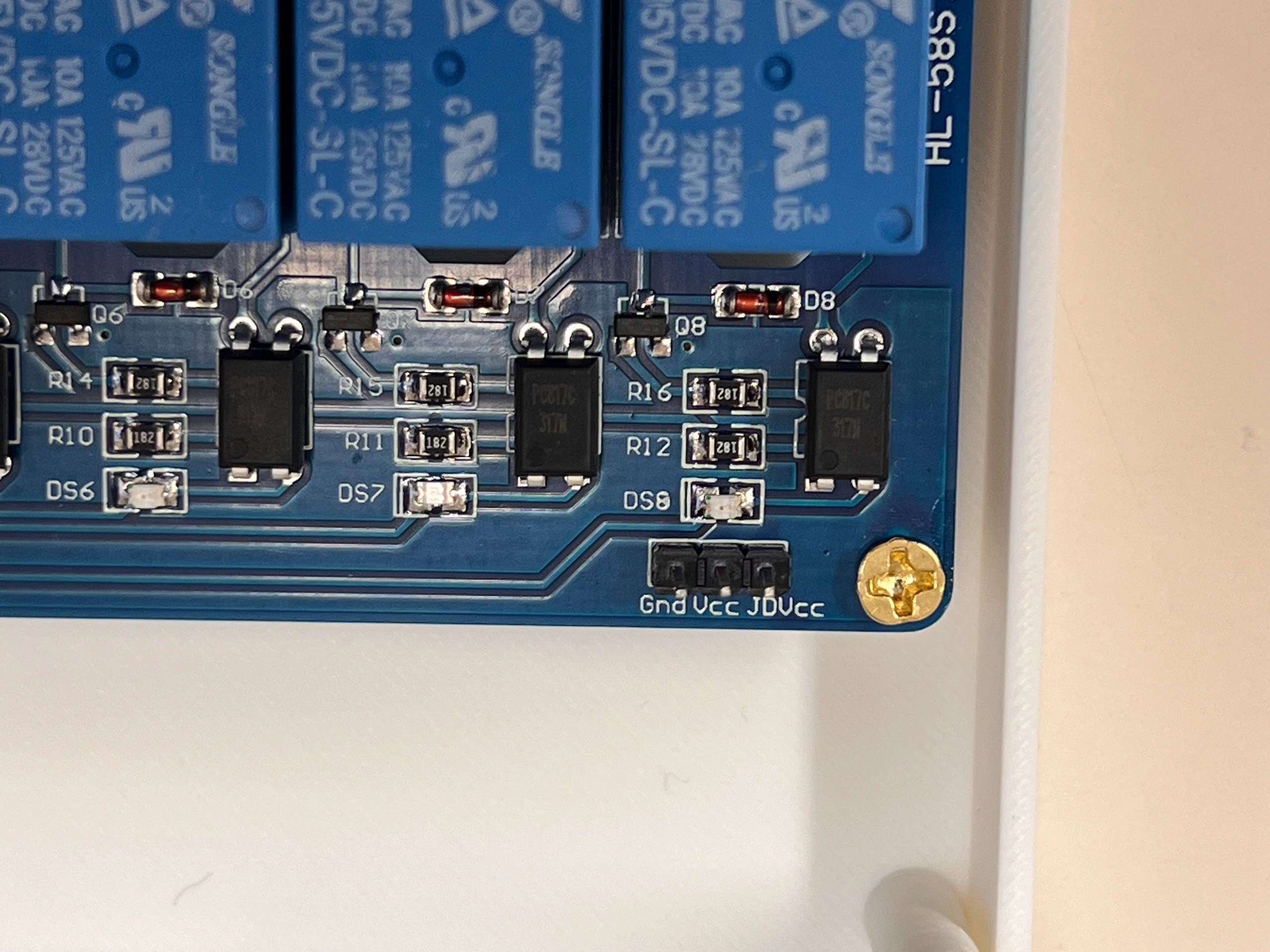
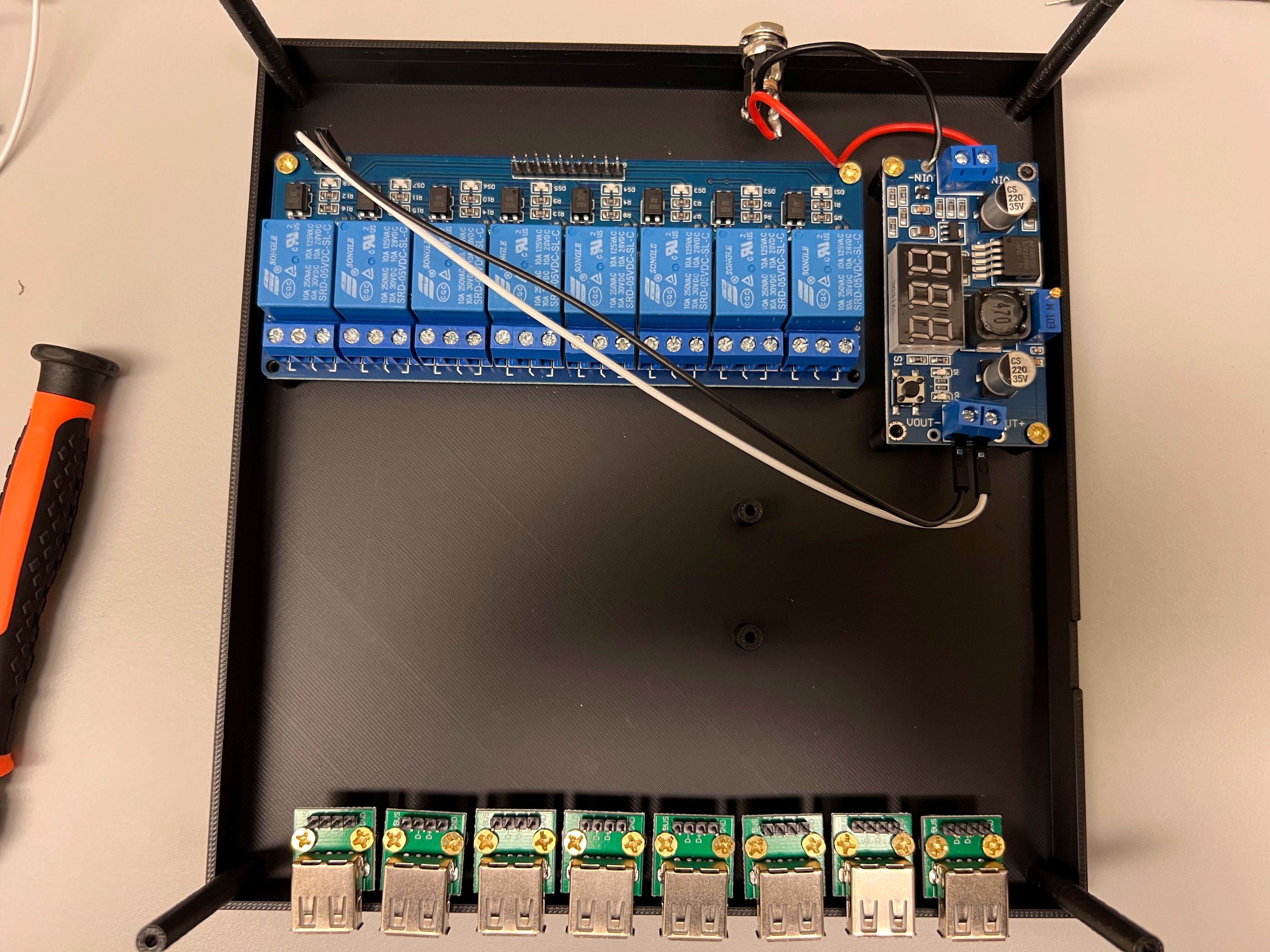
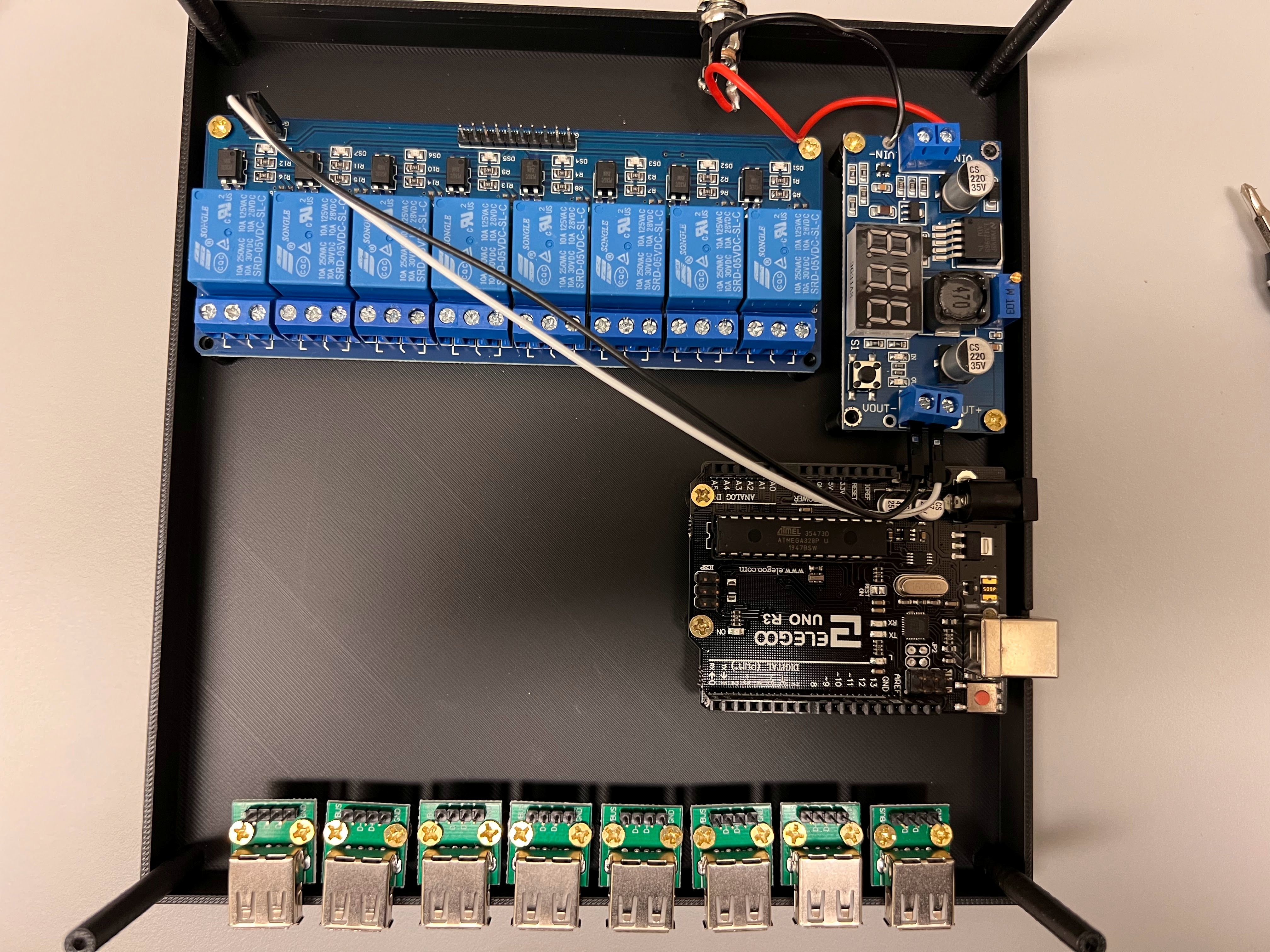
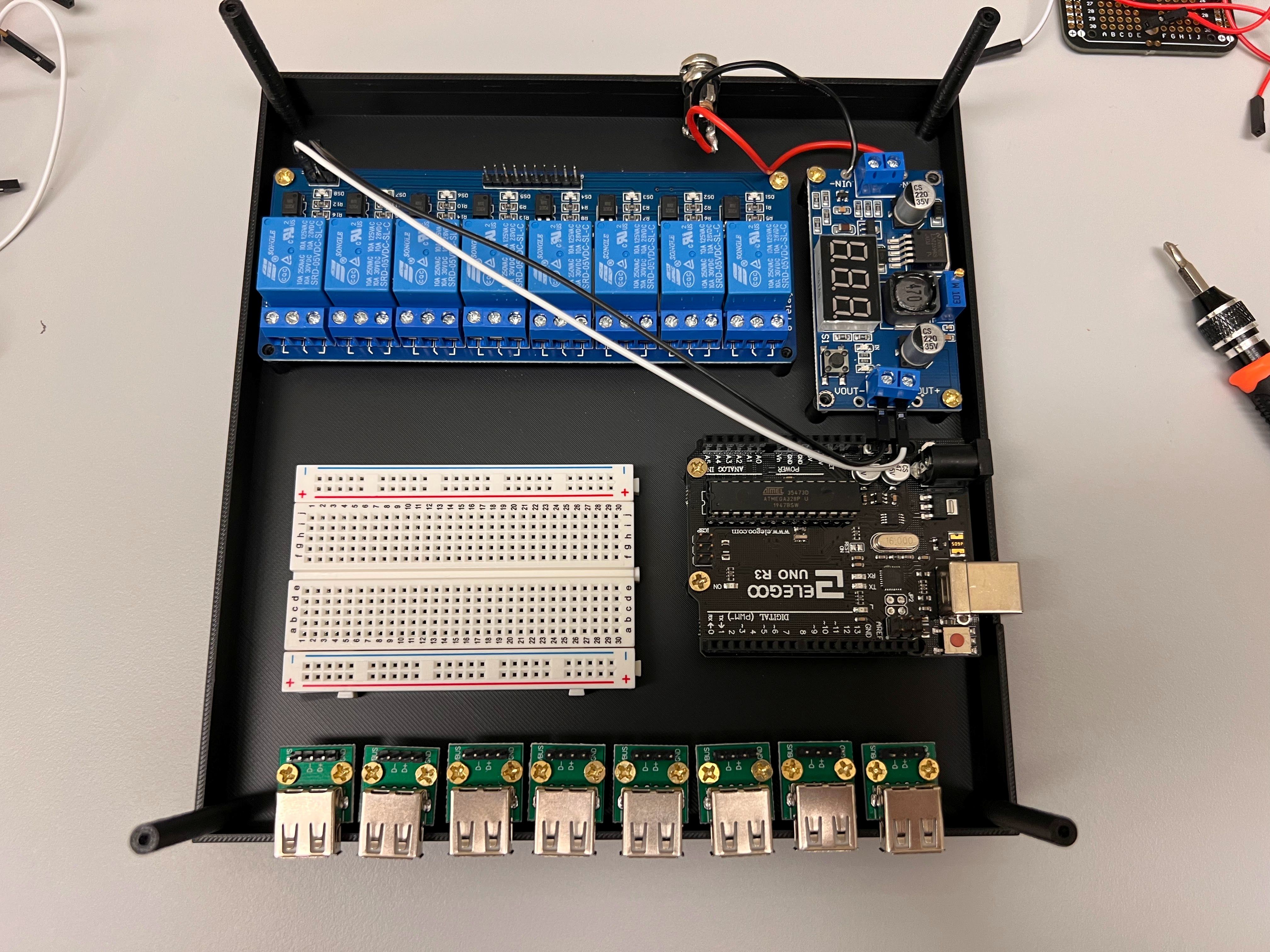
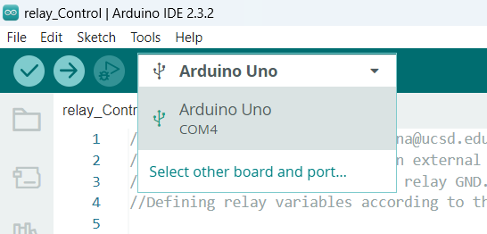
  • We will be using a 8-Channel Relay Board Connected to an Arduino UNO R3 Clone to Control the Flow of Current to the Valves.
  • Here is a great Youtube video that explains how this works.
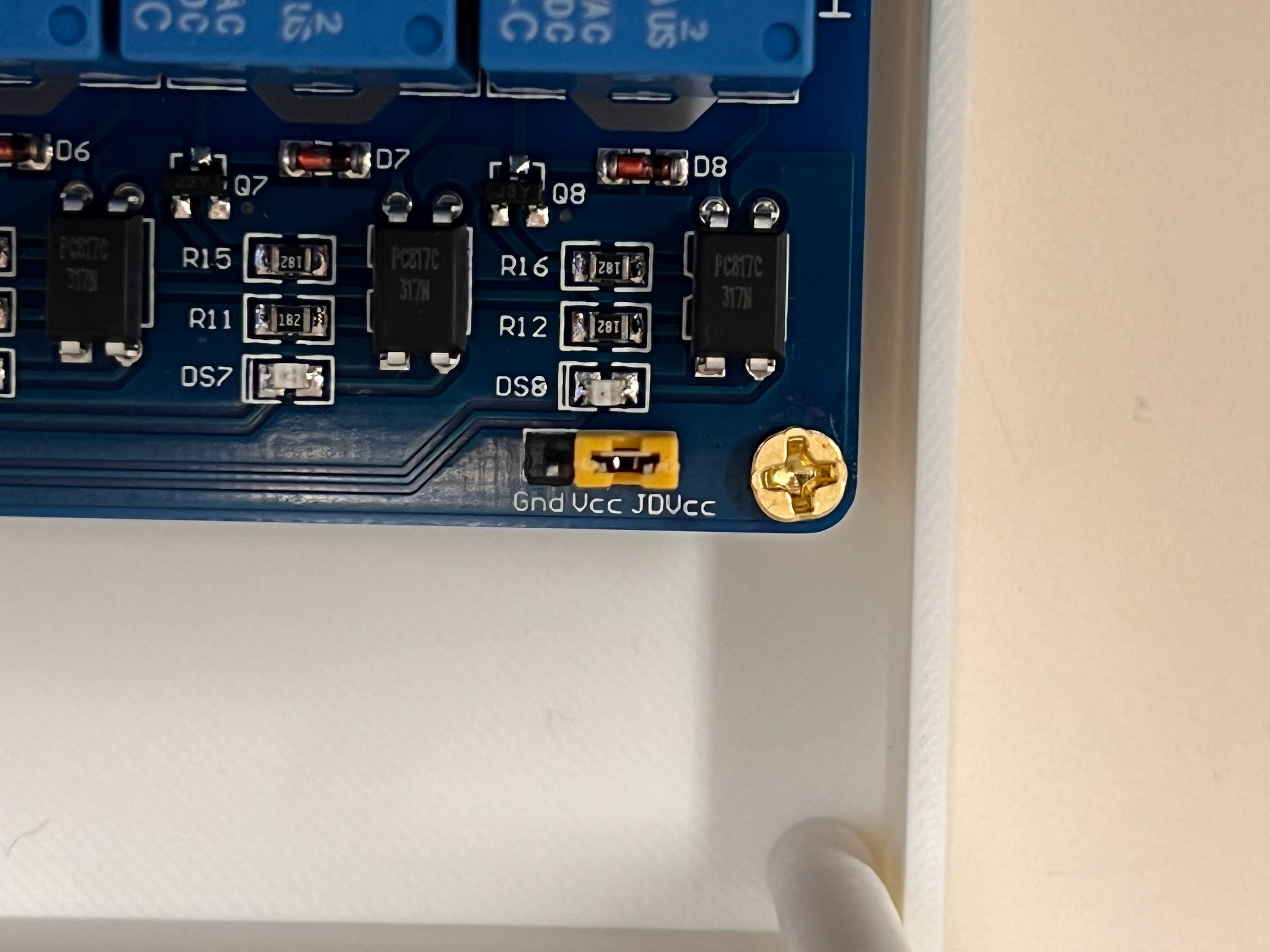
  • The 8-Channel Relay requires an Optically Isolated 5V DC Power Supply.
  • The Arduino UNO R3 Clone can be operated using the Power from the USB Port Alone.
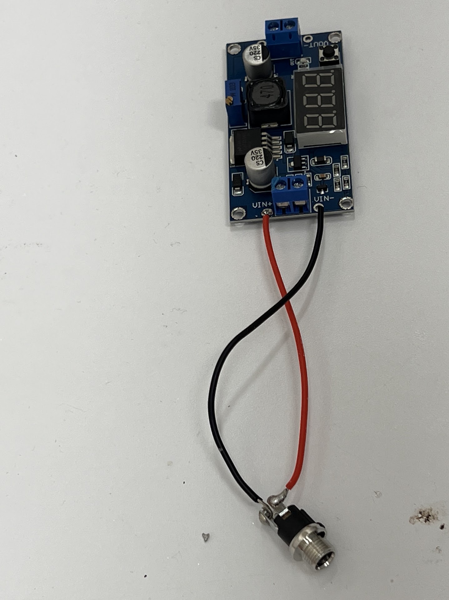
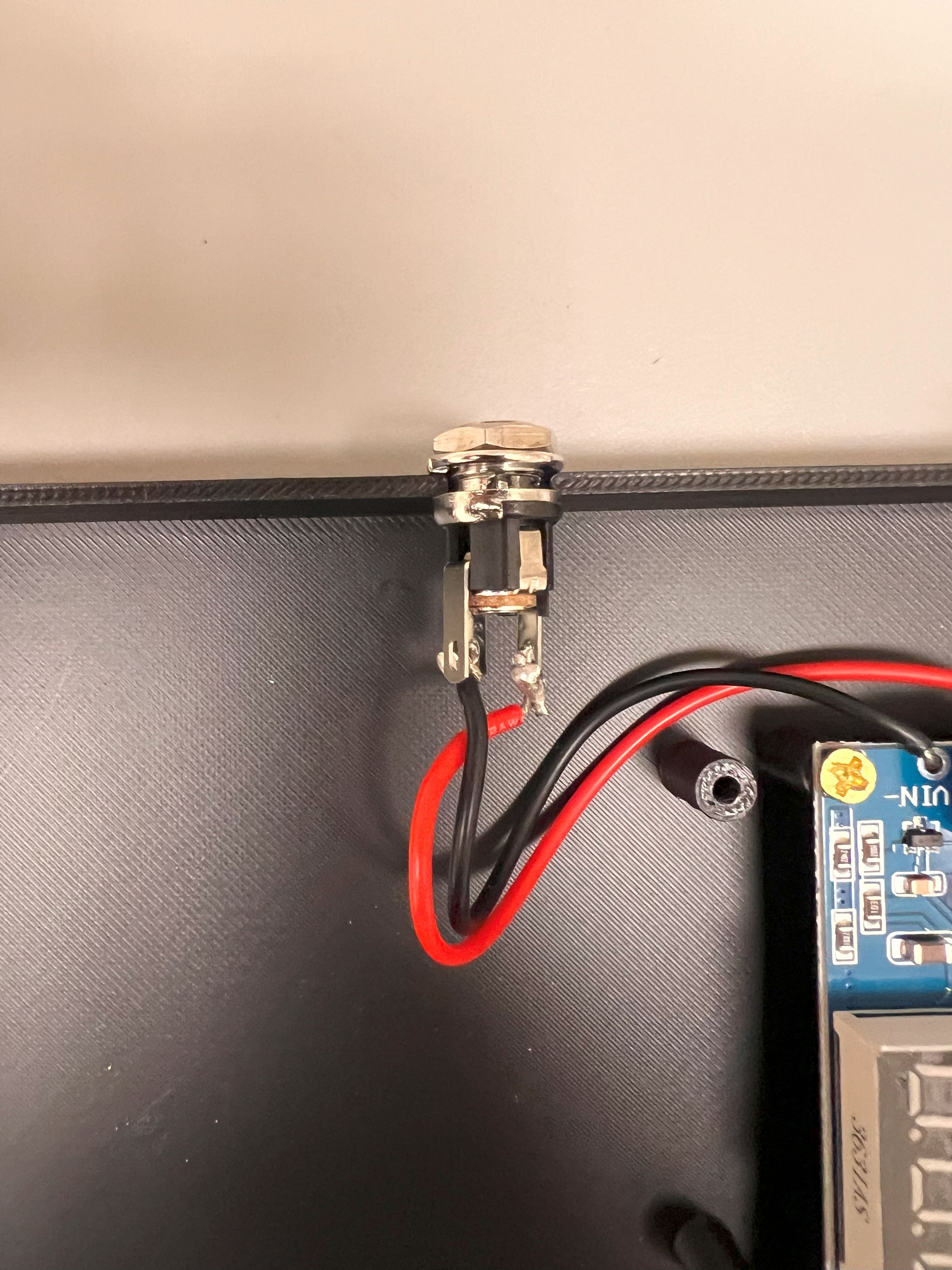
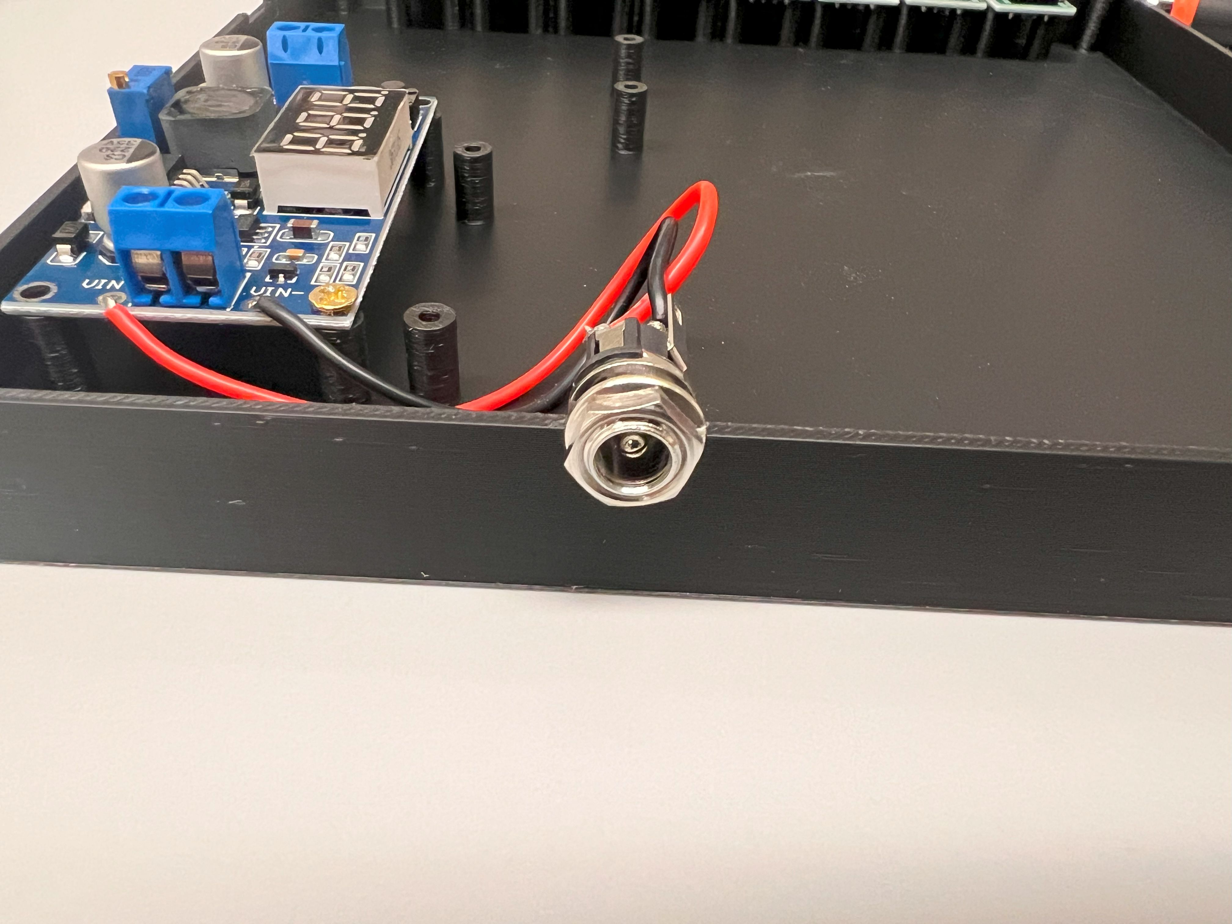
  • We could have used a separate 5V Power supply to power the 8-Channel Relay. But we will be using a DC-DC Buck Converter to Step Down the 24V DC to 5V DC for the 8-Channel Relay instead. This way we can use a Single Power Source for all the Components.
  • You can watch this Youtube Video to learn how it works.

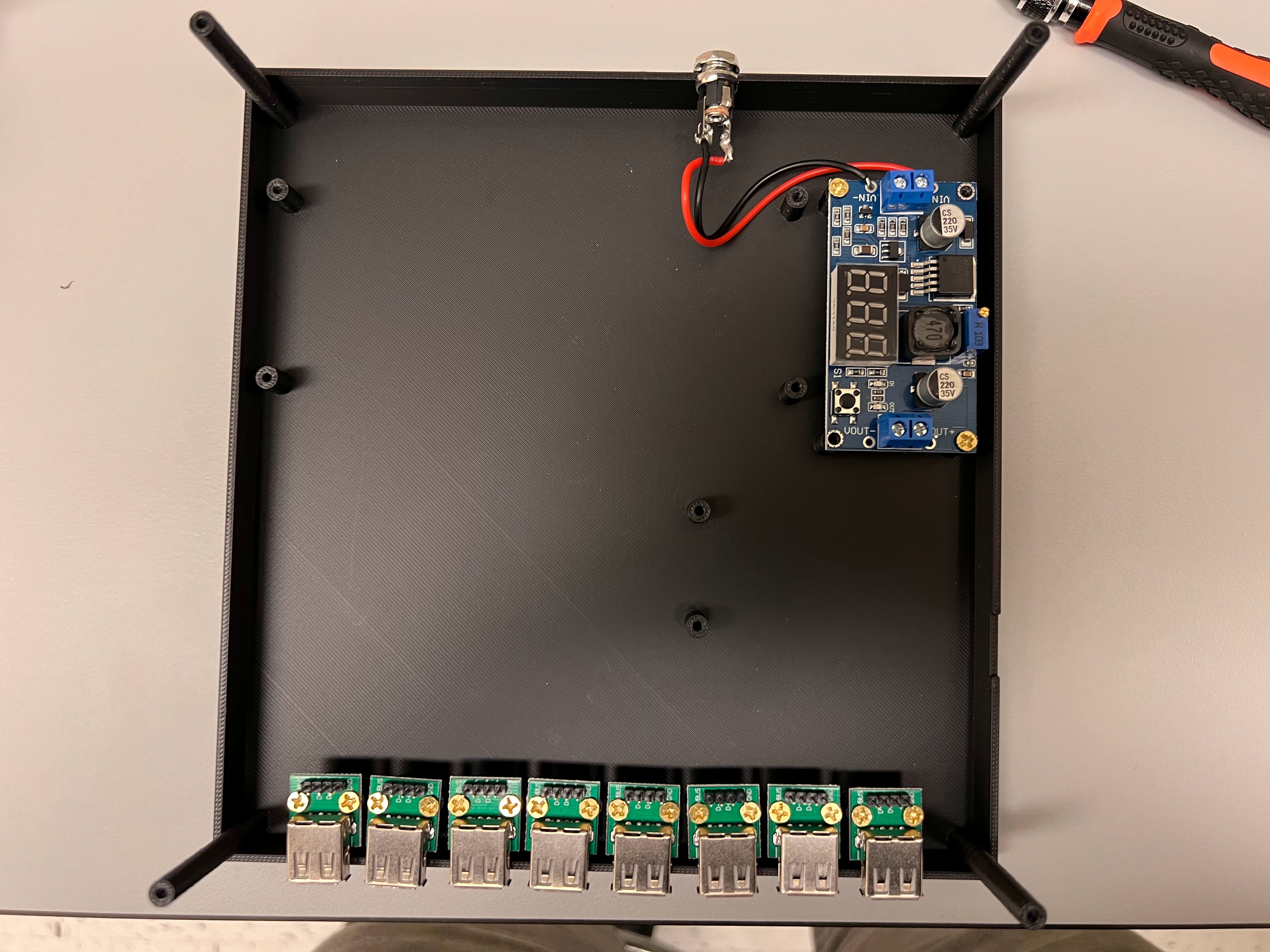
3D Printing Valve Controller Housing

  • We used a Bambu Lab X1 Carbon to print the Housing.
    • 0.4mm Nozzle
    • Textured PEI Plate
  • We generated a 3MF File with all the Settings we used for the Print. You can open this file on the Orca Slicer.
  • The Original STEP Files and F3D Files can be found in this directory.
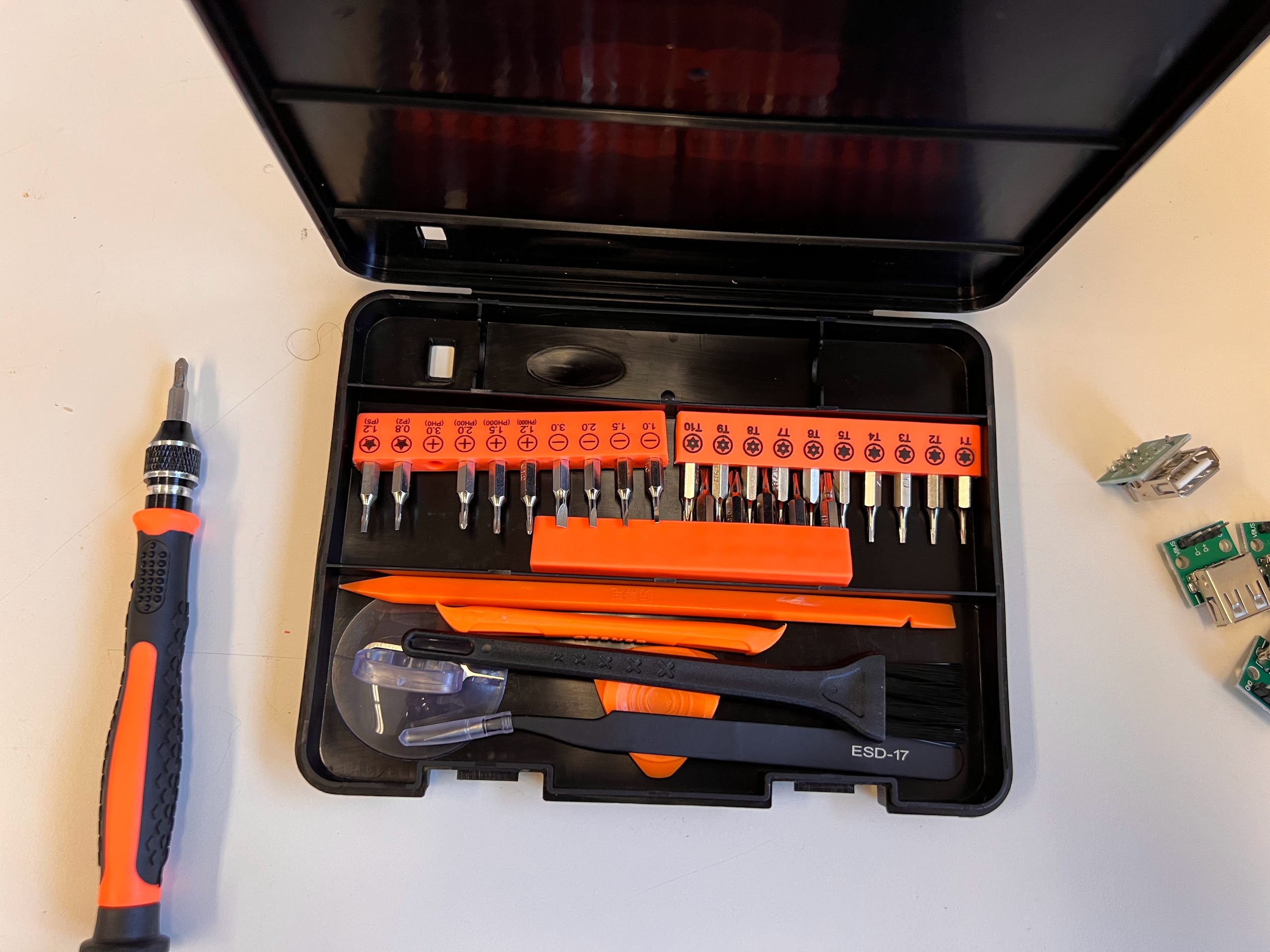
  • We recommend getting a 3D Printing Accessories Kit if you haven't purchased one already.
    • Its extremely helpful in removing supports and cleaning up the print.

Soldering the Valves to a Male USB A 2.0 Connector

  • You will need a Soldering Kit and Lead Free Solder to get Started.
  • Solder Fumes can cause Asthma and Lung Irritation. Its important to setup your Soldering Station Inside a Fume Hood.
    • Make sure you wear your Lab Coat, Gloves, and Safety Glasses.
    • Setup your Soldering Iron inside the Fume Hood.
    • Keep the Sash Closed with two small opening on the Sides so your Hands can reach inside the Fume hood, while keeping your body protected.
  • On the SMC Valves the Red Wire is for Positive Voltage(+VE) and the Black wire is for Ground(-VE).
  • We will be using 1m long USB 2.0 A Cables for Connecting the Valve Controller to the Valves.
    • We will Solder these USB Cables to the Valves.
    • These USB Cables Only have two wires one red for +VE and one black for -VE.
  • Using the Wire Strippers included in the Soldering Kit remove additional parts of the Wire sheaths for both the SMC Valves and USB Cables.
    • Execute the Cell Below to Watch a Video of the Process.
In [10]:
%%HTML
<iframe width="800" height="600" src="https://www.youtube.com/embed/p1VI65QQhWY?si=CWPvj3usDdU_QkLi" title="YouTube video player" frameborder="0" allow="accelerometer; autoplay; clipboard-write; encrypted-media; gyroscope; picture-in-picture; web-share" referrerpolicy="strict-origin-when-cross-origin" allowfullscreen></iframe>
  • Next Twist the exposed wires for the +VE(Red) and -VE (Black) wires for both the SMC Valve and USB Cable together.
    • Execute the Cell Below to Watch a Video of the Process.
In [11]:
%%HTML
<iframe width="800" height="600" src="https://www.youtube.com/embed/X3Tl9_7uTFo?si=i8DHLYbLa7ghG9fs" title="YouTube video player" frameborder="0" allow="accelerometer; autoplay; clipboard-write; encrypted-media; gyroscope; picture-in-picture; web-share" referrerpolicy="strict-origin-when-cross-origin" allowfullscreen></iframe>
  • Inside the Fume Hood solder the Twisted wires together.
    • Then cover the exposed wires with Electrical tape.
    • I used Blue Electrical tape for the -VE wires.
    • I used Red Elecrrical tape for the +VE wires.
    • I then covered both with White Electrical tape.
Solder the Twisted +VE and -VE wires together. Cover the +VE and -VE Wires with Red and Blue Tape Respectively Cover Both Wires with White Electrical Tape
  • Connect the Valve to the USB 2.0 Breakout Board.
    • The +VE Terminal is the VBUS Pin Mount Hole
    • The -VE Terminal is the GND Pin Mount Hole.
  • We can use a Multimeter to make sure the +VE and -VE Wires are not shorted.
    • Set the Multimeter to the correct setting where it beeps whenever its two leads are shorted.
    • You can see connect the probes to VBUS and GND. If you hear beeping then there is a short.
    • Execute the Cell Below to learn how to check for shorts using a Multimeter.
In [9]:
%%HTML
<iframe width="800" height="600" src="https://www.youtube.com/embed/wZQJJu3BVaQ?si=W5087UyYZDekMvWc" title="YouTube video player" frameborder="0" allow="accelerometer; autoplay; clipboard-write; encrypted-media; gyroscope; picture-in-picture; web-share" referrerpolicy="strict-origin-when-cross-origin" allowfullscreen></iframe>
  • To check if the Valve is operating correctly you can use an Adjustable DC Power Supply.
    • Set the Power Supply to 24V DC.
    • Screw the Caps off the +VE and -VE terminals on the Power Supply.
    • Now connect the leads on the Multimeter to the +VE(Red) and -VE(Black) terminals.
    • Connect the Black Probe to the GND and Red Probe to the VBUS Pin Mounting Holes on the USB 2.0 Breakout Board.
    • Press the Output button.
    • If your valve is working correctly, you will hear the Valve Turn on with a Click sound.
    • You can also feel the Mechanical Switching of the Solenoid if you hold the Valve in your hands.
    • About 60mA of Current flow should be shown by the Power supply.
    • Execute the Cell Below to Watch a Video of the Process.
In [8]:
%%HTML
<iframe width="800" height="600" src="https://www.youtube.com/embed/eU7W66oj7ew?si=qCxQSxp7oD1-nW6u" title="YouTube video player" frameborder="0" allow="accelerometer; autoplay; clipboard-write; encrypted-media; gyroscope; picture-in-picture; web-share" referrerpolicy="strict-origin-when-cross-origin" allowfullscreen></iframe>
  • Repeat the above steps for all the Valves you plan to use with the ChronoSeq Device.

Soldering Header Pins to the USB Breakout Board

  • Break off 4 header pins from the Header Pin Strip.
  • Inside the Fume Hood Solder these pins to the USB Breakout Boards.
Soldered Header Pins Top View. Soldered Header Pins Bottom View
  • You will need to solder 8 USB Breakout Boards for each Valve Controller.
    • Check for shorts between the VBUS and GND Pins using the Multimeter.
    • There should be no beeping if you did everything right.

Attaching the Breakout Boards to the Valve Controller Housing

  • We will now attach these USB Breakout Boards to the Bottom Valve Controller Housing. For this you will need:
    • An Electronics Screwdriver set.
    • M3 Self Tapping Screw set.
Screwdriver Set Self Tapping Screw Set
  • Using M3 6mm Self Tapping Screws and the 3.0(PH0) Screwdriver Head:
    • Screw the USB Breakout Boards in the positions shown in the Bottom Valve Controller Housing below.
  • Check to make sure you can easily place the Valve Controller Top Housing on the Bottom Housing without any obstruction.
    • Do not screw the Housing together. We are just checking for obstruction.
    • Adjust the Breakout Boards if necessary to Align with the holes in the Top Housing.

Assembling Input DC Barrel Connector

  • We will need a 24V DC Power Supply for our Valve Controller.
    • The symbol indicated below on the power supply tells us what parts of the Adapter DC Barrel Plug is positive and which part is negative (Ground)
  • The DC Power Supply is a Male Type connector, we need a DC Female Connector to power our Valve Controller.
  • The DC Female Connector Breaks out into three pin on the back.
    • These pins are of three sizes. Small, Medium and Large.
    • The smallest pin is connected to the inner part of the DC Barrel connector. Therefore this pin will be +VE 24V.
    • The Medium sized pin is connected to the outer part of the DC Barrel connector. Therefore this pin will be -VE (Ground).
Large Pin for Female DC Barrel Medium Pin for Female DC Barrel (-VE/Ground) Small Pin for Female DC Barrel (+VE 24V DC)
  • Strip and cut 11cm of Red and Black Electrical wire.
    • Twist the ends of the Exposed wire
    • Twist and Tie the Red Wire through the Smallest Pin of the Female DC Barrel.
    • Twist and Tie the Black Wire though the Medium Size Pin of the Female DC Barrel.
  • Inside the Fume Hood, Solder the Tied Wires to their respective pins in the Female DC Barrel.

Assembling the DC-DC Buck Converter

  • Strip the Sheath off the other ends of the Red and Black Wires connected to the Female DC Barrel.
    • Remember to then twist the exposed wires.
  • Solder the Red Wire to the +VIN Mount Hole and the Black wire on the -VIN Mount Hole on the Buck Converter.
    • Apply solder on the back side of the Buck Converter PCB.
  • Using M3 6mm Self Tapping Screws and the 3.0(PH0) Screwdriver Head:
    • Screw the Buck Converter in the positions shown in the Bottom Valve Controller Housing below.
    • Apply one screw to the top left corner and another screw to the bottom left corner position on the Buck Converter PCB.
  • Use the Multimeter to check for Shorts between the +VIN and -VIN Terminals of the Buck Converter.
  • Using the included Nut and Spacer with the Female DC Barrels:
    • Screw the Barrel into the back of the Bottom Valve Controller Housing, as shown below:
Mounted Female DC Barrel Top View Mounted Female DC Barrel Back View

Setting the Buck Converter to an Output Voltage of 5V

  • We will first check to make sure there are no incorrect shorts in our assembled circuit.
    • Make sure the +VIN is connected to the +VIN of the Screw Terminal.
    • Also make sure the -VIN is connected to the -VIN of the Screw Terminal.
    • The +VIN should also be connected to the Shortest pin of the DC Female Barrel Connector.
    • The -VIN should be connected to the Medium pin of the DC Female Barrel Connector.
    • The -VIN and -VOUT should also be connected.
    • The +VIN and -VIN should not be connected.
  • There is a Button on the right side of the Buck Converter PCB that displays the input and output voltages.
  • The LED Indicator tells you whether its showing you the input voltage or output.
  • Press the Button once to display the Input Voltage and then check this voltage using the Multimeter.
    • Always trust the Multimeter Value above the Buck Converter value.
    • The Buck Converter displayed value gives a good estimate but the Mulitimeter should be considered the Gold Standard.
  • Press the Button again to display the Output Voltage.
  • Now using a Flat head 1.5 Screw head rotate screw on the top of the Buck Converter Anti-clockwise till you see the Output Voltage going down.
  • Keep rotating the screw anti-clockwise till you are close to 5V.
  • Verify this voltage using the Multimeter.
  • We made a video for the previous version of the Valve Controller. Execute the Cell below to watch a video of the process.
In [6]:
%%HTML
<iframe width="800" height="600" src="https://www.youtube.com/embed/NSGyDSS8A6o?si=Hj2SeqhVqWXHubWR" title="YouTube video player" frameborder="0" allow="accelerometer; autoplay; clipboard-write; encrypted-media; gyroscope; picture-in-picture; web-share" referrerpolicy="strict-origin-when-cross-origin" allowfullscreen></iframe>

Connecting the 8-Channel Relay

  • Now disconnect the 24V DC Power. Remember to only make new connections when the POWER IS DISCONNECTED.
  • Using M3 6mm Self Tapping Screws and the 3.0(PH0) Screwdriver Head:
    • Screw the 8-Channel Relay Board into the Position shown below.
    • Place a screw only in the Top-left and Top-right screw holes.
  • You will see a Yellow Cap Connecting the VCC to JDVCC on the 8-Channel Relay Board.
    • We will remove this Yellow Cap to Optically Isolate the Relays and Provide Separate power to the Relay Board.
Yellow Cap Connecting JDVCC to VCC With Yellow Cap Removed
  • Now all Connection we make will be made using Jumper Ribbon Cables.
  • You will need a 3.0(PH0) Screwdriver Head to unscrew the +VOUT and -VOUT Screw Terminals.
  • You will also need two Male to Female Jumper Cables.
    • For the first Cable, connect the Male Exposed Contact of the Jumper Cable to the +VOUT of the Buck Converter.
      • Now Connect the Female Contact to the JDVCC Pin on the 8-Channel Relay.
    • For the second Cable, connect the Male Expose Contact of the Jumper Cable to the -VOUT of the Buck Converter.
      • Now Connect the Female Contact to the GND Pin on the 8-Channel Relay.
    • We are now suppling 5V DC Optically Isolated Power to the 8-Channel Relay via our Buck Converter.
    • We made a video for the previous version of the Valve Controller. Execute the Cell Below to watch a Video of the Process:
In [7]:
%%HTML
<iframe width="800" height="600" src="https://www.youtube.com/embed/AeBoMDQxR0c?si=SnWP-SDf5ORfmEci" title="YouTube video player" frameborder="0" allow="accelerometer; autoplay; clipboard-write; encrypted-media; gyroscope; picture-in-picture; web-share" referrerpolicy="strict-origin-when-cross-origin" allowfullscreen></iframe>
  • Using M3 6mm Self Tapping Screws and the 3.0(PH0) Screwdriver Head:
    • Screw the Arduino UNO R3 Clone into the Position shown below.
    • Place a screw only in the Top-left and Bottom-left screw holes.
    • Make sure the USB Port on the UNO R3 is aligned with its hole.
  • Remove the paper covering the adhesive back from a Breadboard.
    • Then press down to attach the Breadboard to the position shown.
  • We will now connect our Breadboard to +24V DC using the Input Screw Terminals on the Buck Converter. You will need two Male to Male Jumper cables:
    • For the first Cable, connect the Male Exposed Contact of the Jumper Cable to the +VIN of the Buck Converter.
      • Now Connect the other Male Pin to the Upper Positive Rail on the Breadboard.
    • For the second Cable, connect the Male Expose Contact of the Jumper Cable to the -VIN of the Buck Converter.
      • Now Connect the other Male Pin to the Lower Negative Rail on the Breadboard PCB.
  • Using a Male to Female Jumper Cable, Connect the 5V Pin on the UNO R3 to the VCC Pin on the 8-Channel Relay as Shown Below.
  • We now want to test our 8-Channel relay.
    • Using a Male to Female Jumper Cable, Connect Pin 13 on the UNO R3 to the In1 Pin on the 8-Channel Relay.
    • We can now control the rightmost relay using our UNO R3.

Connecting the UNO R3 to the Computer and Uploading a Sketch

  • We will now connect our UNO R3 to our Windows Computer using the provided USB Cable.
  • Download and Install the Arduino IDE.
  • You will need to open the Relay Control Sketch.
  • Execute the Cell Below to Watch a Video on how to Upload the Sketch to your Arduino UNO R3 Clone Board.
In [5]:
%%HTML
<iframe width="800" height="600" src="https://www.youtube.com/embed/kh7ov1MiJSw?si=DhQtNCZ9lKObEcmO" title="YouTube video player" frameborder="0" allow="accelerometer; autoplay; clipboard-write; encrypted-media; gyroscope; picture-in-picture; web-share" referrerpolicy="strict-origin-when-cross-origin" allowfullscreen></iframe>
  • Connect the 24V DC Power supply.
  • You can now send commands to the UNO R3 using the Serial Monitor on the Arduino IDE.
  • In our case we will be sending a string of 8 Numbers. These numbers can be either a 0 or a 1.
  • Each Relay has three Terminals.
    • The Middle terminal is the floating/Common (COM) terminal and can be connected to the left or right terminal.
    • The left terminal is called the Normally Open (NO) terminal since it gets connected to the Middle Terminal(COM) only when its powered ON.
    • The right terminal is called the Normally Closed (NC) terminal sinces its normally connected to the Middle Terminal(COM) when there is no power.
    • You would have noticed this terminology is very similar to the NO and NC Ports on a 3:2 SMC Valve.
  • Since we have wired up the rightmost Relay we can turn the relay on by sending the string "00000001" to the UNO R3.
  • We can then turn off the Relay by sending the string "00000000". The last digit represents whether the rightmost relay is on or not.
  • We made a video for the previous version of the Valve Controller. Execute the Cell Below to watch a video of the Relay switching in action.
In [4]:
%%HTML
<iframe width="800" height="600" src="https://www.youtube.com/embed/3iGeyLzMS-s?si=JMo-dvfuMywdqgJg" title="YouTube video player" frameborder="0" allow="accelerometer; autoplay; clipboard-write; encrypted-media; gyroscope; picture-in-picture; web-share" referrerpolicy="strict-origin-when-cross-origin" allowfullscreen></iframe>

Connecting the 8-Channel Relay to SMC Valve

  • Disconnect the 24V Power Supply.
  • We will need four Jumper Wires and one 1N4007 Diode to connect the rightmost USB 2.0 Breakout Board with the rightmost Relay.
    • You will need a 3.0(PH0) Screwdriver Head for the Screw Terminals on the Relay Board.
    • Remember to Screw the Male Jumper Contact Pin all the way into the Screw Terminal.
    • Try Tugging the Male Jumper out to make sure the Connection to the Screw Termial is secure.
    • Using a Male-to-Male Jumper Wire :
      • Connect the Middle(COM) Terminal of the Rightmost relay to the Upper Positive Rail on the Breadboard.
      • The COM Terminal will now be at +24V DC when the power supply is connected later.
    • Using a Female-to-Male Jumper Wire :
      • Connect the GND Header of the rightmost USB Breakout board to the lower Negative Rail on the Breadboard.
      • Now our GND on the rightmost USB Breakout board is at the same voltage as GND/-VE on the DC Power Supply.
    • Using a Male-to-Male Jumper Wire :
      • Connect the Left(NO) Terminal of the rightmost relay to Position E15 on the Breadboard.
      • Now E15->A15 will have the same voltage as the NO Terminal of the rightmost relay.
    • Connect the -VE Teminal of the 1N007 Diode to C15 and the +VE Terminal to the Lower Negative rail of the Breadboard.
      • WARNING: Connecting this Diode in the incorrect orientation is dangerous as this will cause a short circuit.
      • We are connecting this Diode in reverse orientation so no current will flow during normal operation through it.
      • This Diode is connected in parallel to the Solenoid valve and will help dissapate the backwards current from the Solenoid when the relay is turned off.
      • The ring on one end of the diode generally indicates its -VE Terminal.
    • Using a Female-to-Male Jumper Wire:
      • Connect the VBUS(+VE) Header of the rightmost USB Breakout board to A15 on the Breadboard.
      • Now VBUS(+VE) on the rightmost USB Breakout board is at the same voltage as the NO Terminal of the rightmost relay.
  • Connect an SMC Valve to the rightmost USB Breakout Board via the USB Port.
  • Connect the 24V Power Supply.
  • Connect the UNO R3 to your Computer Via USB.
  • We can now turn our Valve ON or OFF using the Serial Monitor on the Arduino IDE.
    • Since we have wired up the rightmost Relay to our Valve, we can turn the Valve on by sending the string "00000001" to the UNO R3.
    • We can then turn off the Valve by sending the string "00000000".

Finishing the remaining Connections

  • Disconnect the 24V DC Power Supply.
  • Now that we know how to wire up the connection for one Valve, we can do it for the remaining 7 easily.
  • Connect Pins 12->6 on the UNO R3 to In2->In8 Pins respectively on the 8-Channel Relay.
  • Connect the COM Terminal of Relays from right to left to the Breadboard Upper Positive rail.
  • Connect the NO Terminal of the Relays:
    • Lets call the rightmost relay: Relay 8, and the leftmost relay: Relay 1.
    • Connect the NO Terminals as follows:
      • Relay 1 NO Terminal-> E1
      • Relay 2 NO Terminal-> E3
      • Relay 3 NO Terminal-> E5
      • Relay 4 NO Terminal-> E7
      • Relay 5 NO Terminal-> E9
      • Relay 6 NO Terminal-> E11
      • Relay 7 NO Terminal-> E13
  • Connect the GND Header on all the USB Breakout boards to the Breadboard Lower Negative rail.
  • Connect the remaining seven 1N007 Diodes:
    • Connect the -VE Terminal of the diodes (with ring) to C1,C3,C5,C7,C9,C11 and C13
    • Connect the +VE Terminal of the diodes to the Lower Negative rail of the Breadboard.
  • Connect the VBUS Header on the USB Breakout boards:
    • Lets call the rightmost USB Breakout: Breakout 8, and the leftmost USB Breakout: Breakout 1.
    • Connect the VBUS Headers as follows:
      • Breakout 1 VBUS-> A1
      • Breakout 2 VBUS-> A3
      • Breakout 3 VBUS-> A5
      • Breakout 4 VBUS-> A7
      • Breakout 5 VBUS-> A9
      • Breakout 6 VBUS-> A11
      • Breakout 7 VBUS-> A13

Close the Housing

  • Disconnect the 24V DC Power Supply.
  • Disconnect the USB Cable.
  • Press down the Top housing on the Bottom Housing.
  • Make sure the Holes on top are aligned.
  • Using M3 8mm Self Tapping Screws and the 3.0(PH0) Screwdriver Head:
    • Insert the screws in all four corners and tighten.
    • Make sure there are no wires stuck in between the Top and Bottom Housing.
  • Execute the Cell Below to Watch a Video of the Final Product.
In [13]:
%%HTML
<iframe width="800" height="600" src="https://www.youtube.com/embed/8OTM_BlqqBo?si=H4VLlSMjX1JK4MVz" title="YouTube video player" frameborder="0" allow="accelerometer; autoplay; clipboard-write; encrypted-media; gyroscope; picture-in-picture; web-share" referrerpolicy="strict-origin-when-cross-origin" allowfullscreen></iframe>

Controlling the Valve Controller with Python in Jupyter Notebooks

  • Since we have already programmed our Valve Controller to respond to 8 Bit Binary Strings we can now use this to control it within Jupyter notebooks.
  • Connect your Valve Controller to 24V DC.
  • Connect your Valve Controller Via USB to your Computer.
  • You can Identify the COM Port by Connecting and then Disconnecting the Controller and then checking which new COM Port Shows up in Arduino IDE.
    • In our case we can see the Port is COM4
  • Close the Arduino IDE. Closing the IDE Severs the Connection to the Valve Controller. Only one program can connect to the Valve Controller at a Time.
  • We will now Connect to the Valve Controller using PySerial.
In [ ]:
import serial
import time
valveControllerCOMPort="COM4"

ValveController=serial.Serial(valveControllerCOMPort, timeout=1, write_timeout=0)
time.sleep(5.0)
print(ValveController.is_open)
print(ValveController.get_settings())
  • We can now send commands to the ValveController by writing to the Serial Port
  • Lets Turn all the Relays ON. You should hear a clicking sound.
In [ ]:
##This will turn all the Relays ON
ValveController.write("11111111\n".encode())
time.sleep(5.0)
  • Now Lets Turn all the Relays OFF. You should hear another clicking sound.
In [ ]:
##This will turn all Relays OFF
ValveController.write("00000000\n".encode())
time.sleep(5.0)
  • Now we can close the connection to the Valve Controller.
In [ ]:
ValveController.close()

So now we are done. We have successfully assembled and controlled our Valve Controller with Python in our Jupyter Notebook. We will slowly build the other components and bring them all together to assemble our Complete ChronoSeq Device. We can then start orchestrating them together in a single Notebook for more complex behaviors.