Instructions for Assembling XYZ Robot
Brief Description
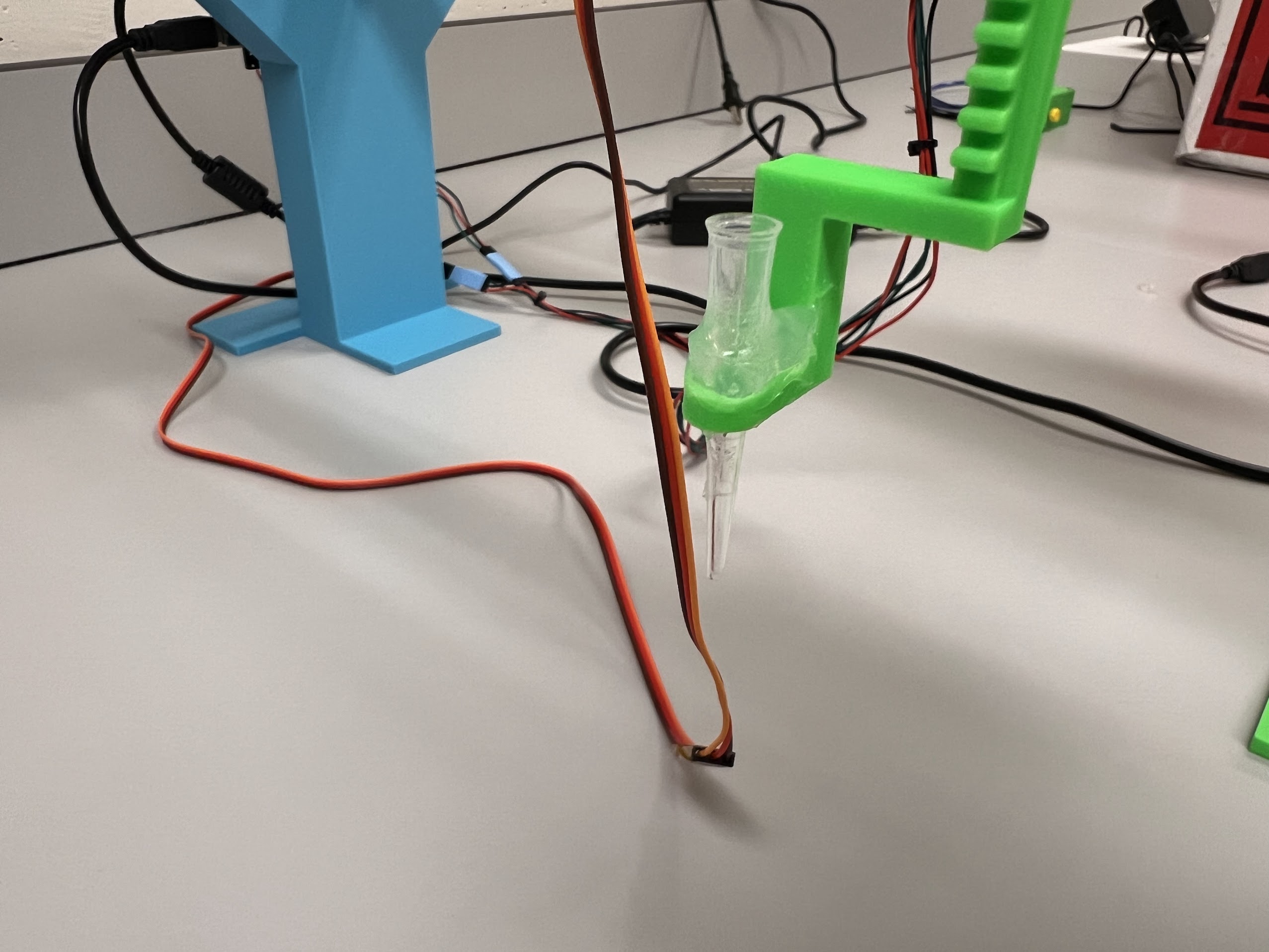
- For each new injection of beads for the ChronoSeq Device:
- We need to make sure the beads from the previous injection are recovered and removed from the Bead Channel.
- By removing the beads we can ensure the Cells being injected in the the microfluidic chip are Tagged by the Correct Time-Tagged Beads.
- In addition we don't want to waste the substantial number of expensive Time-Tagged beads already in the Bead Channel by recovering them for use in later experiments.
- Therefore we deposit the recovered beads in labeled 50ml and 15ml Tubes using the XYZ Robot and the Bead Bypass Valve.
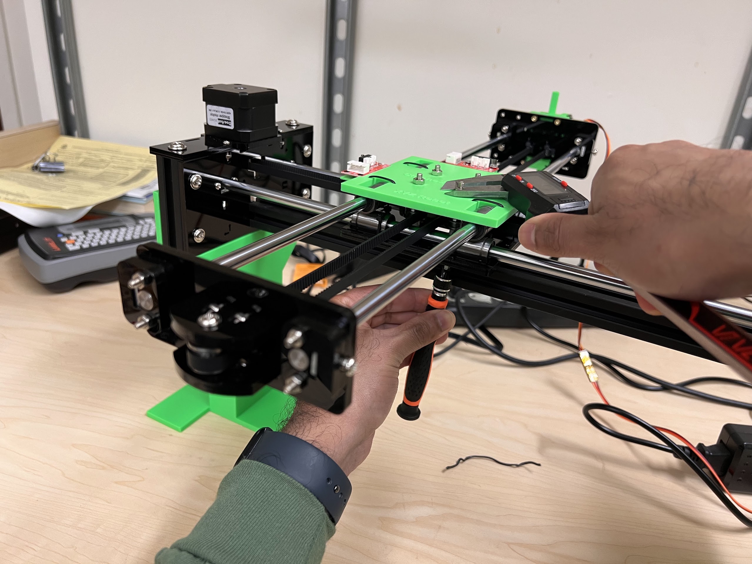
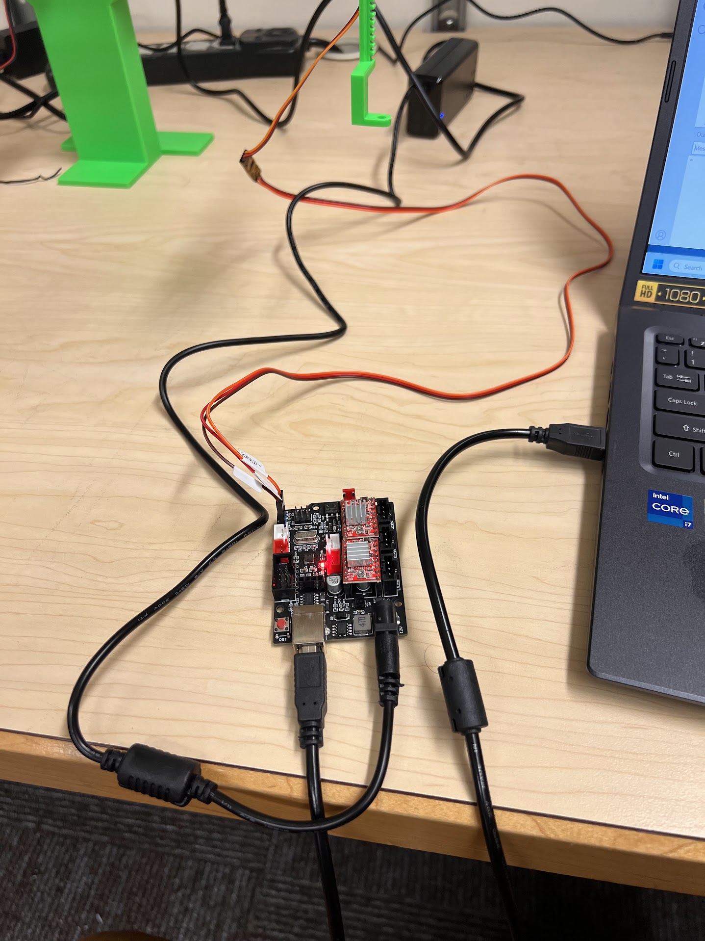
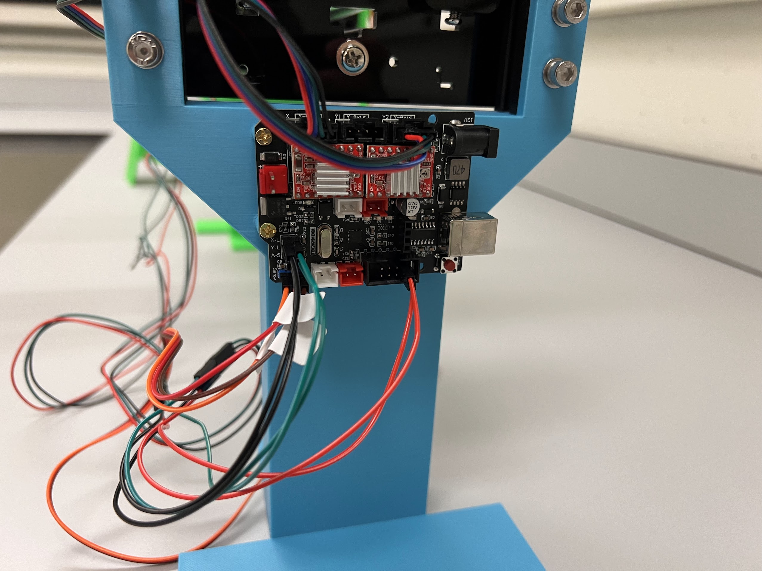
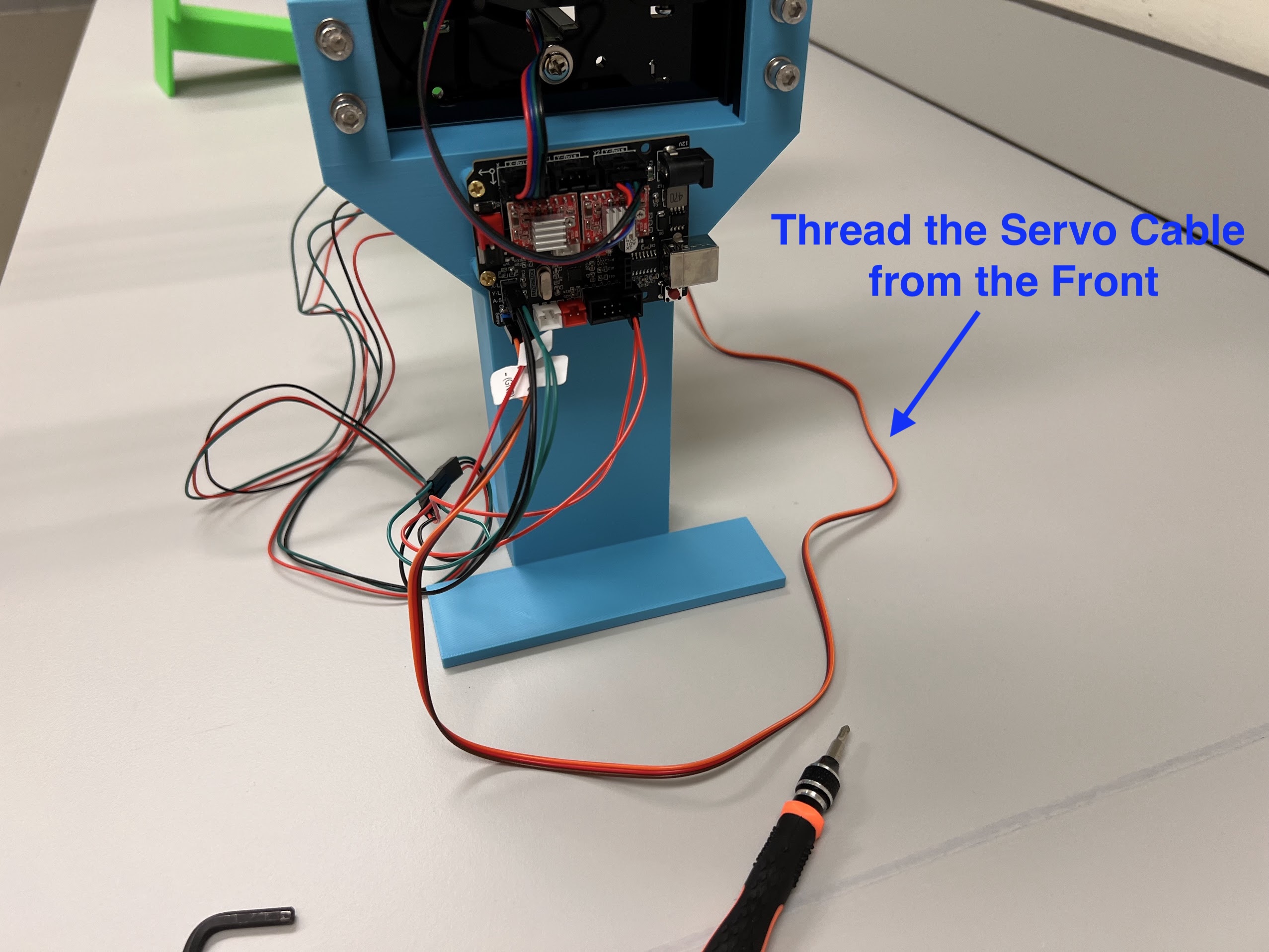
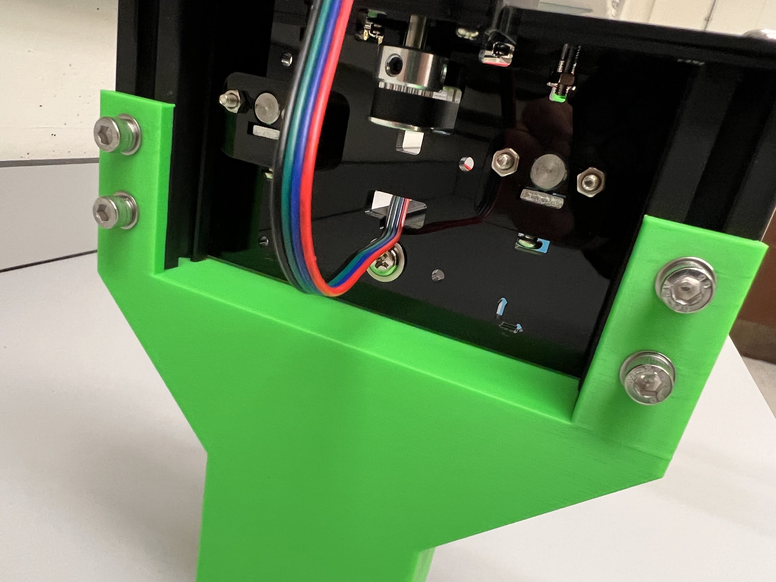
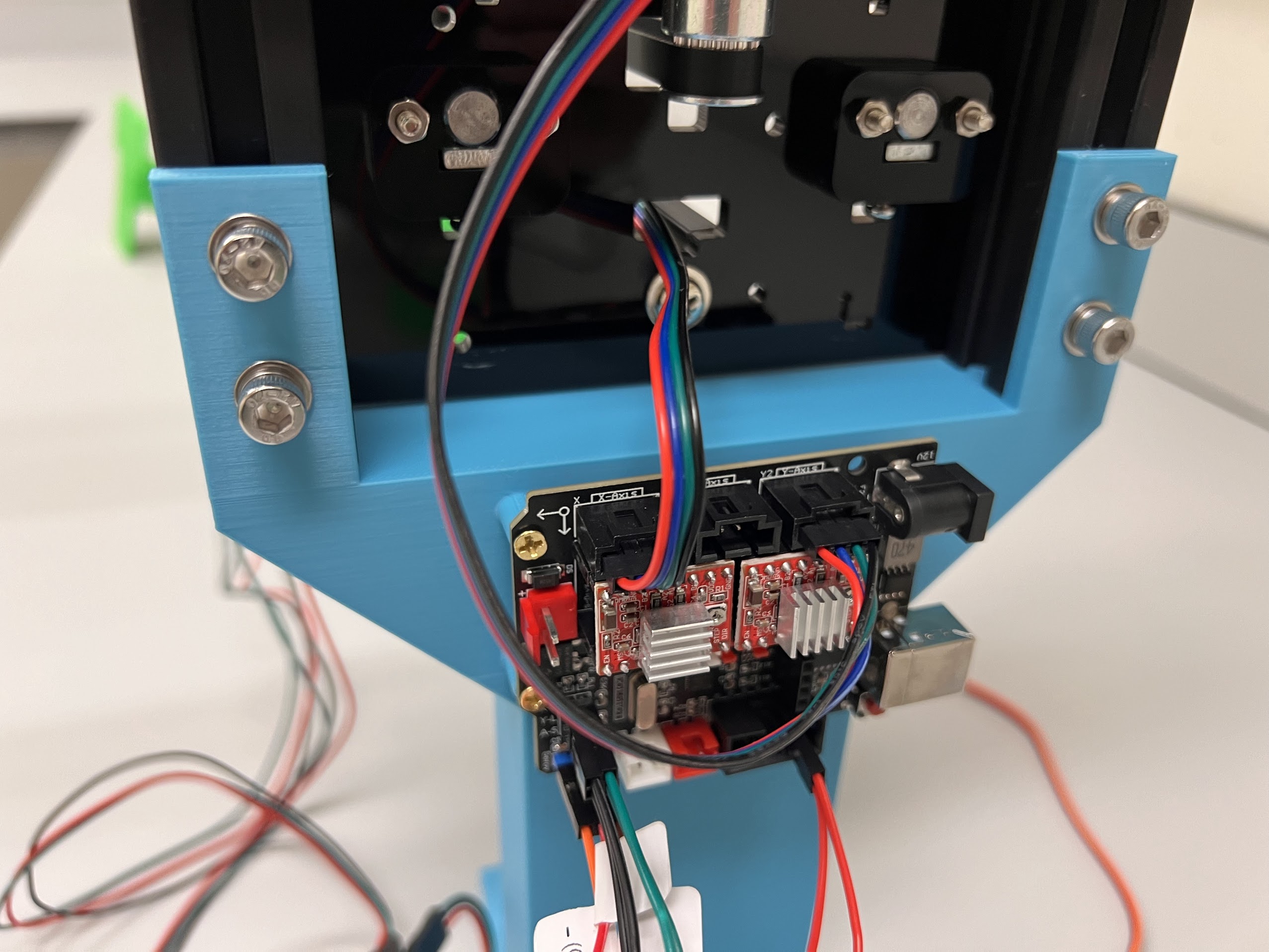
- To Build the XYZ Robot we will modify a GRBL CoreXY Pen-Plotter.
- Although we modified the Doesbot plotter there are many other similar plotters available online and the provided CAD Files can easily be modified for those other Plotters. Most Pen Plotters meant for A4 Size Paper should work.
| Location of XYZ Robot in Schematic |
|---|
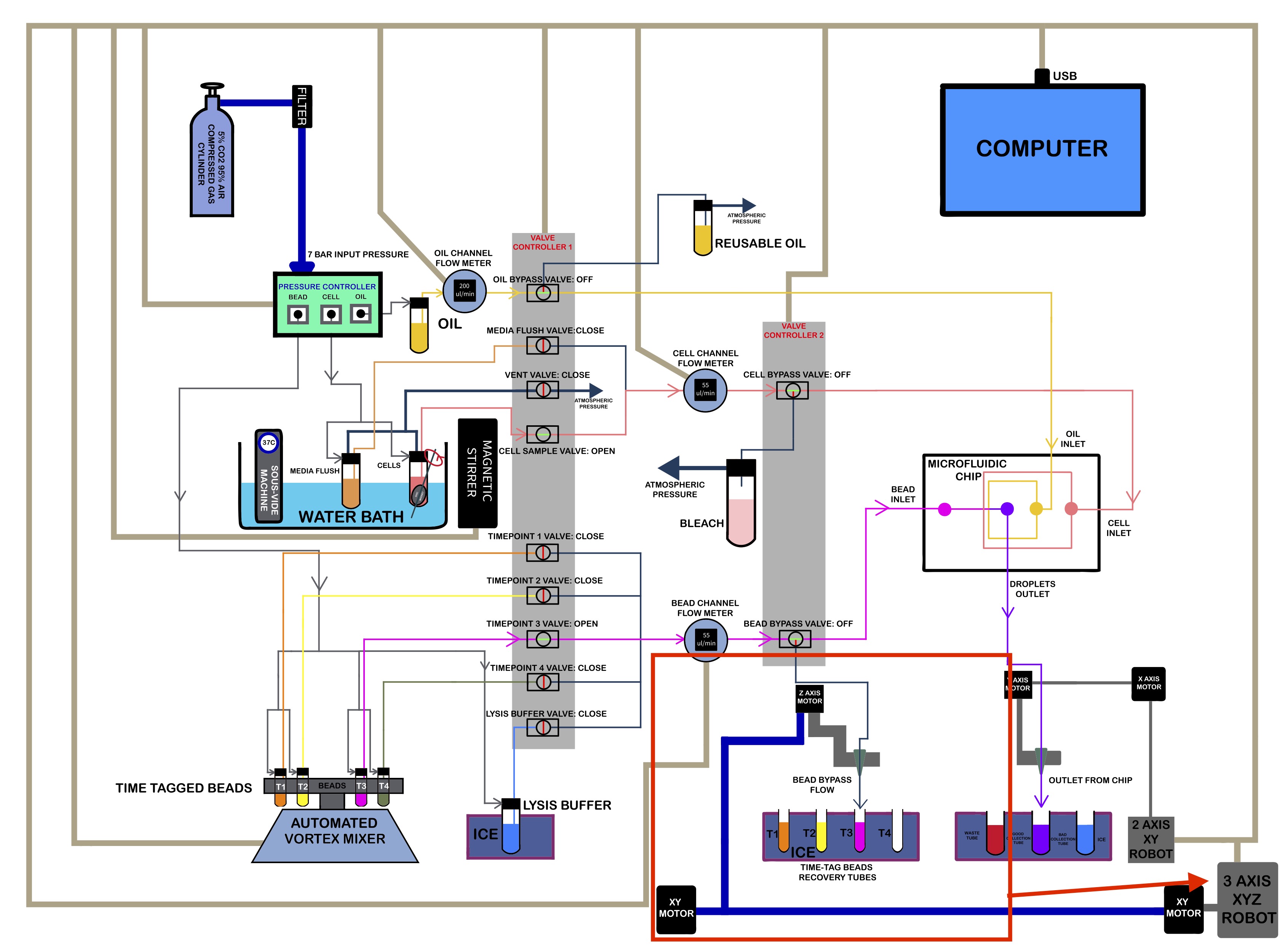 |
3D Printing Parts
- We used a Bambu Lab X1 Carbon to print the Parts.
- 0.4mm Nozzle
- Textured PEI Plate
- We generated several 3MF Files with all the Settings we used for the Print. You can open these files on the Orca Slicer.
- The Original STEP Files and F3D Files can be found in the same directory.
- We recommend getting a 3D Printing Accessories Kit if you haven't purchased one already.
- Its extremely helpful in removing supports and cleaning up the print.
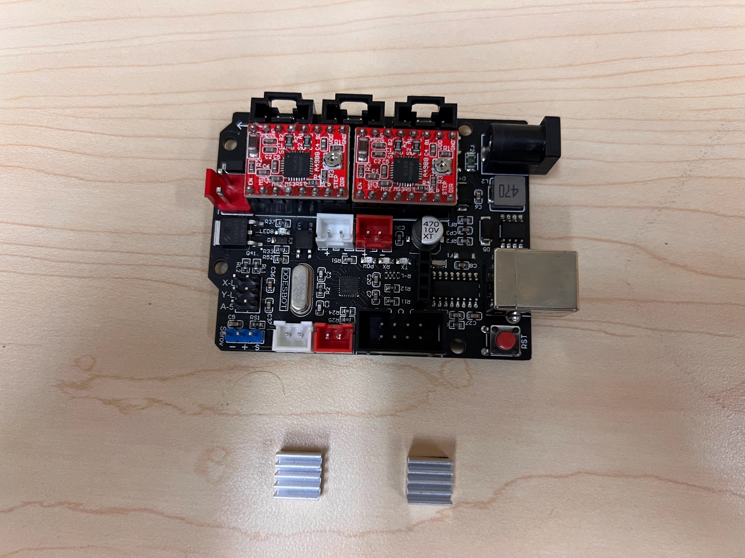
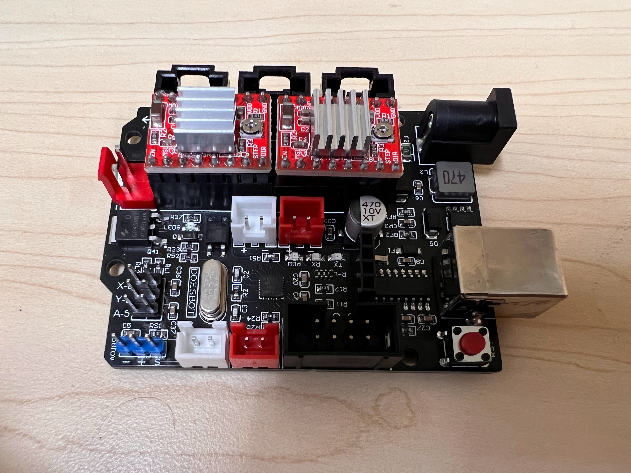
Ordering the Parts
- You can order the Doesbot AX4 from either Amazon or directly from the Doesbot website.
- Limit Switch PCBs.
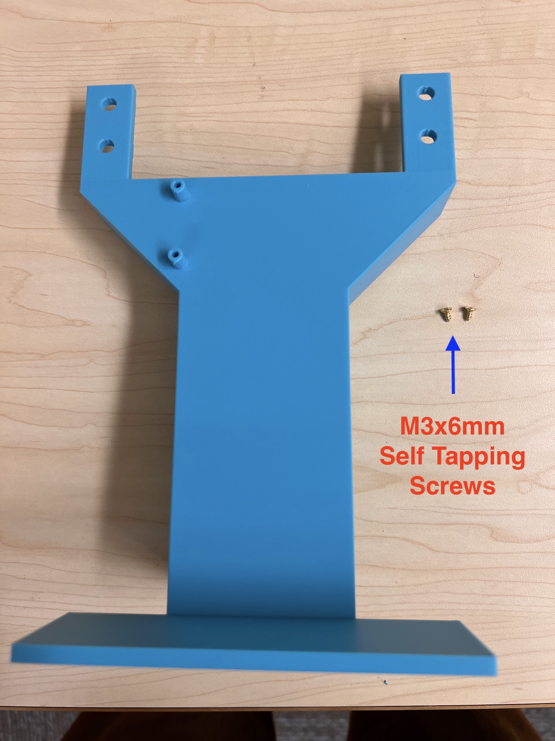
- Self Tapping Screw Set
- We used M3 10mm Screws and M2 10mm Screws.
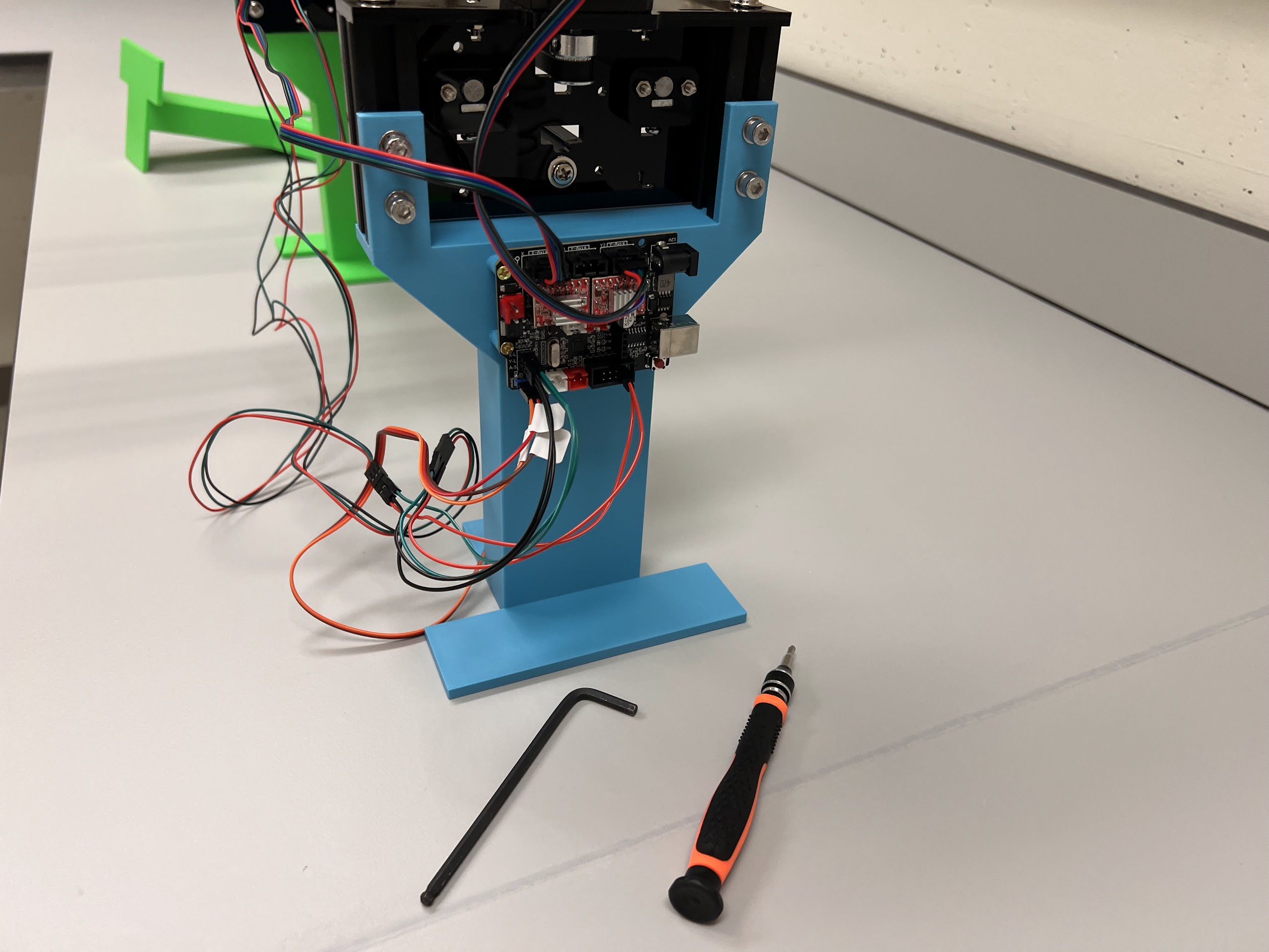
- An Electronics Screwdriver set.
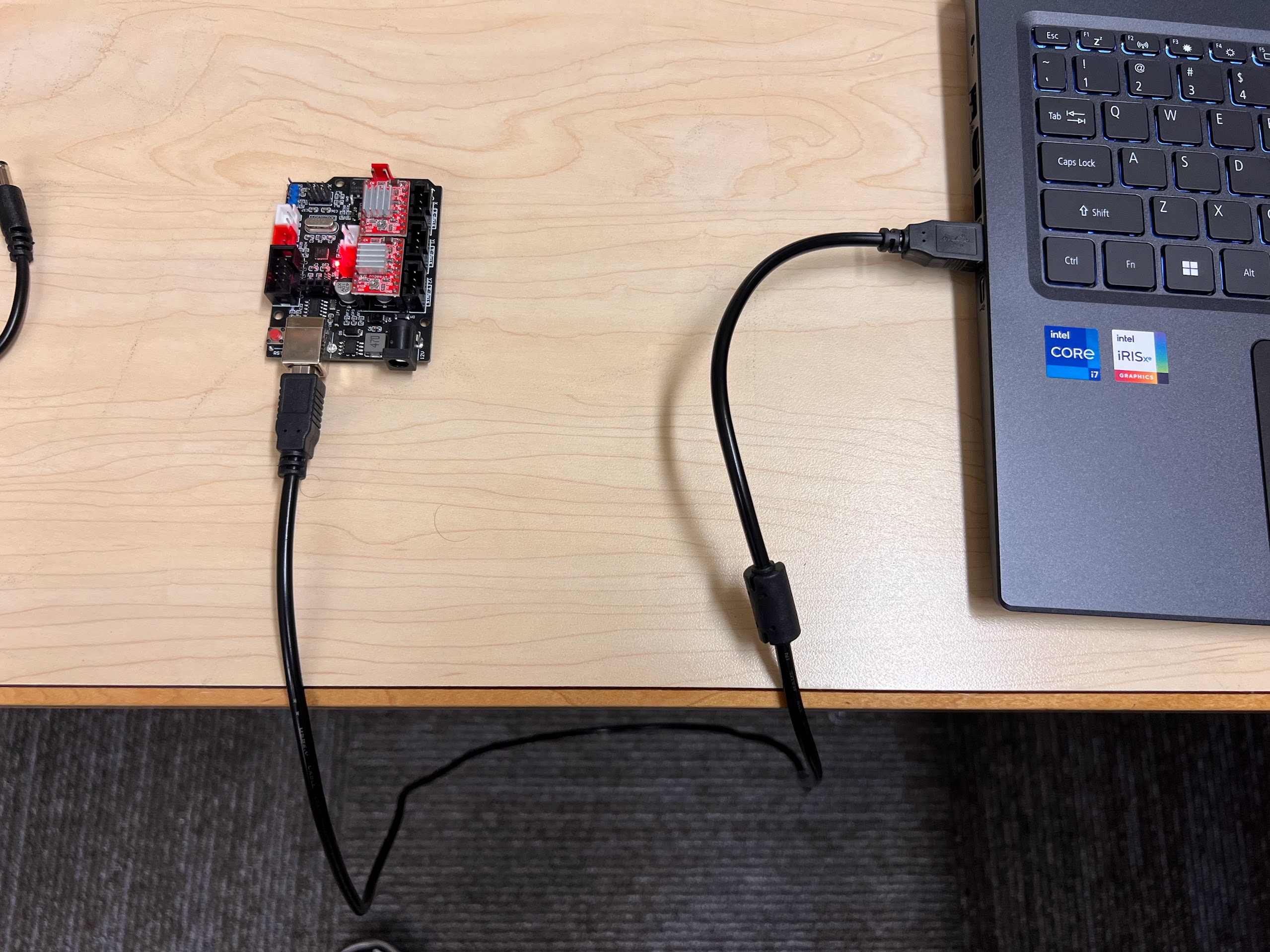
- USB A to USB B Cable
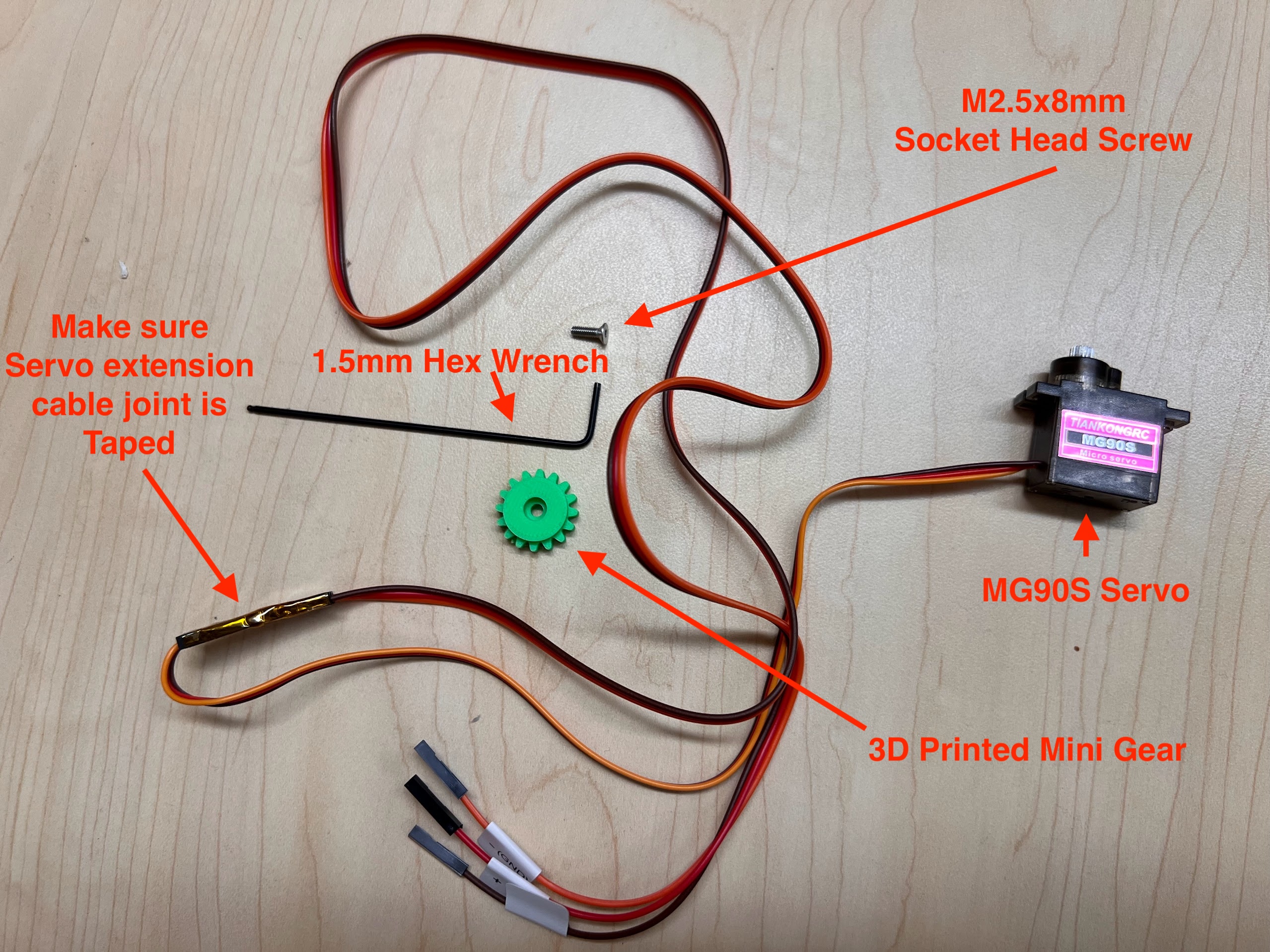
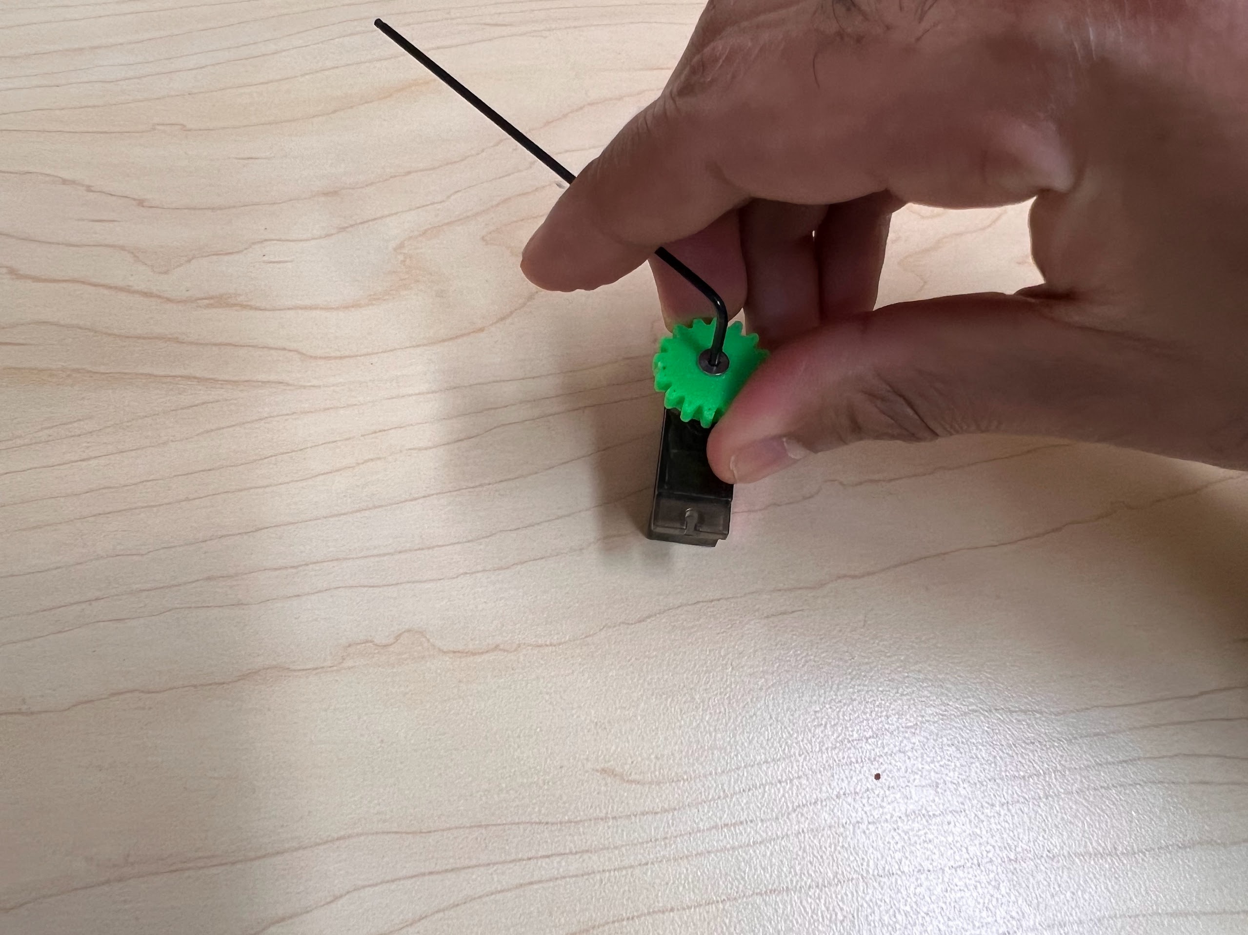
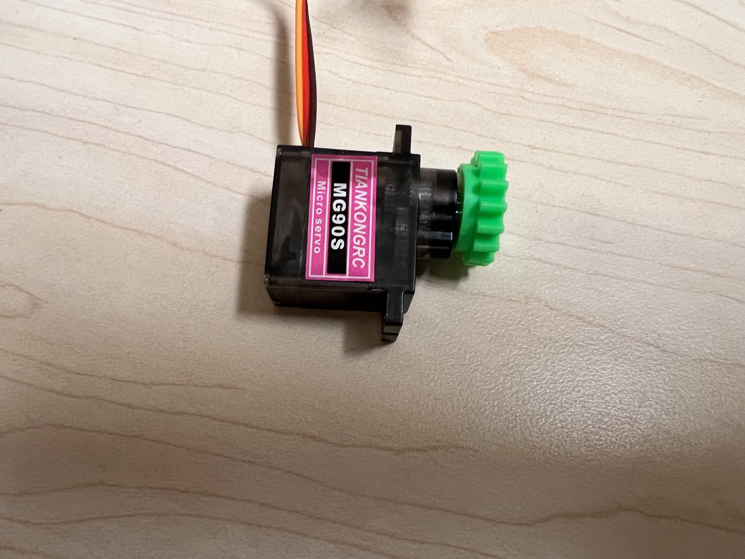
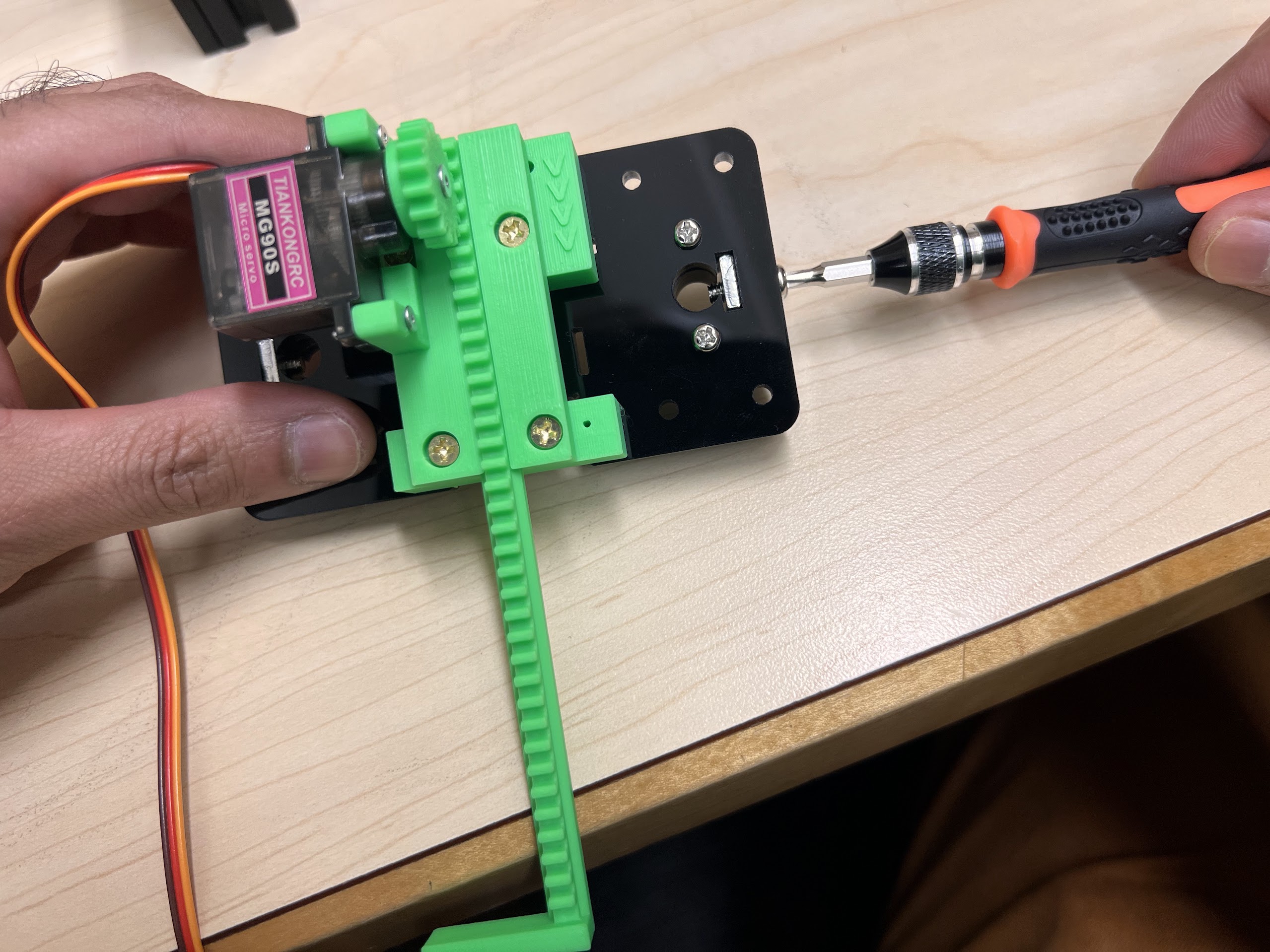
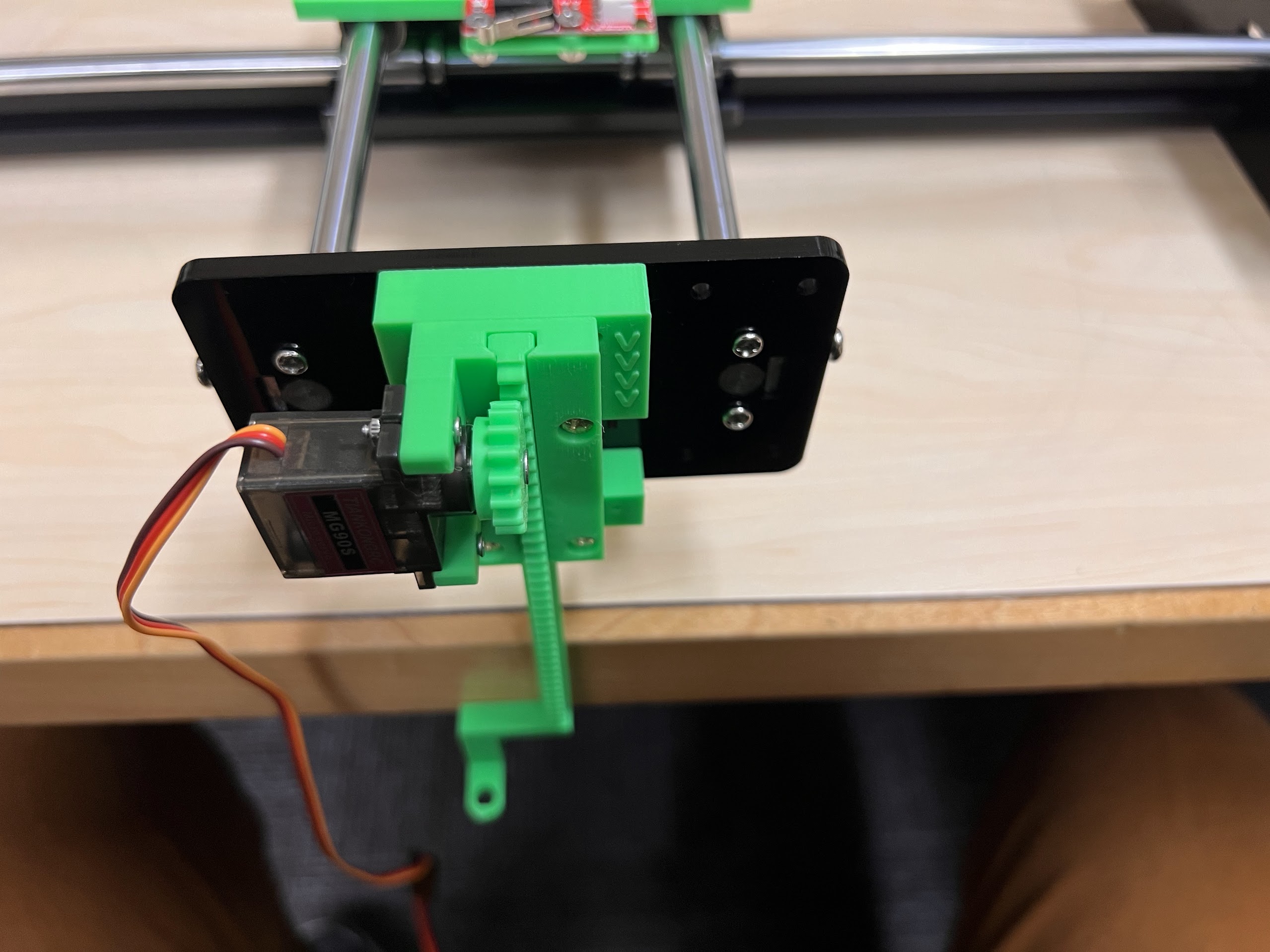
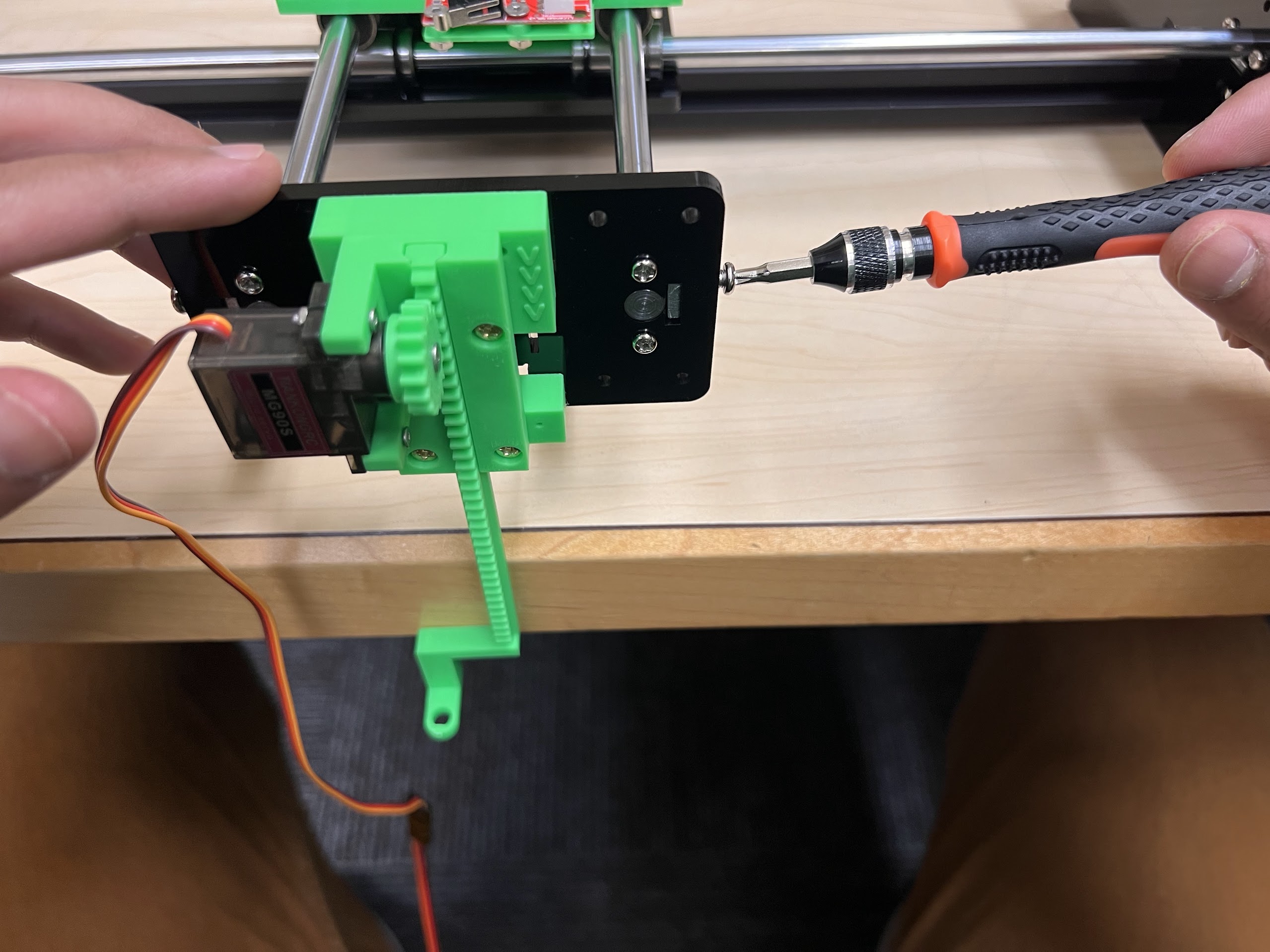
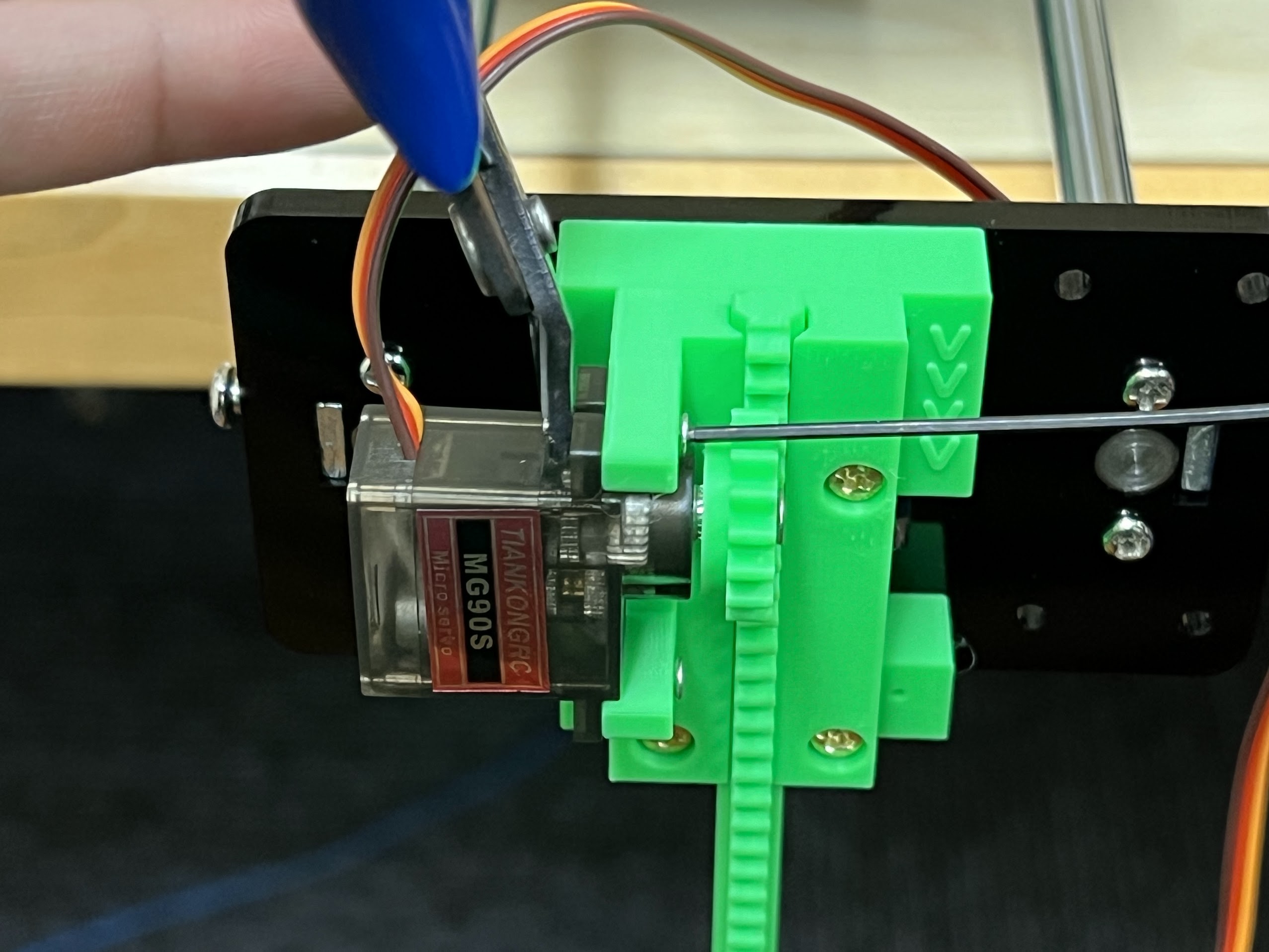
- Extra MG90S 9g Servo if necessary.
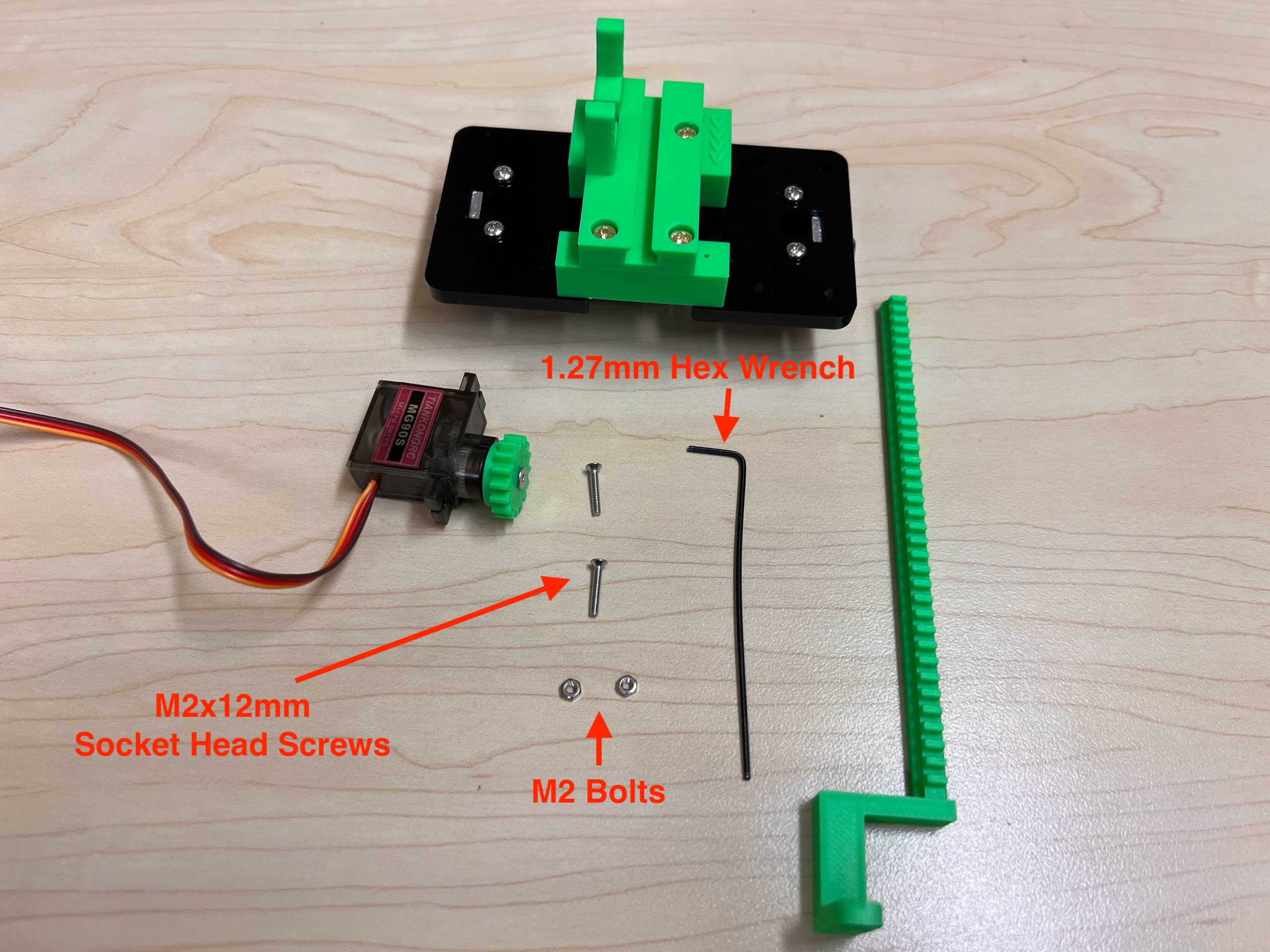
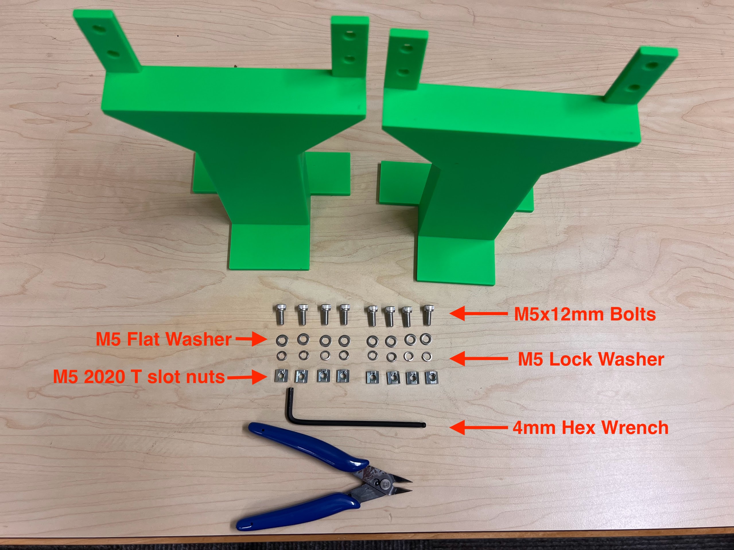
- Socket Cap Bolts Screws Nuts Assortment Kit
- M5 2020 Aluminum Profile T Nuts
- Hex Wrench Metric and Inch Set
- M5 Sockets Head Bolt Kit
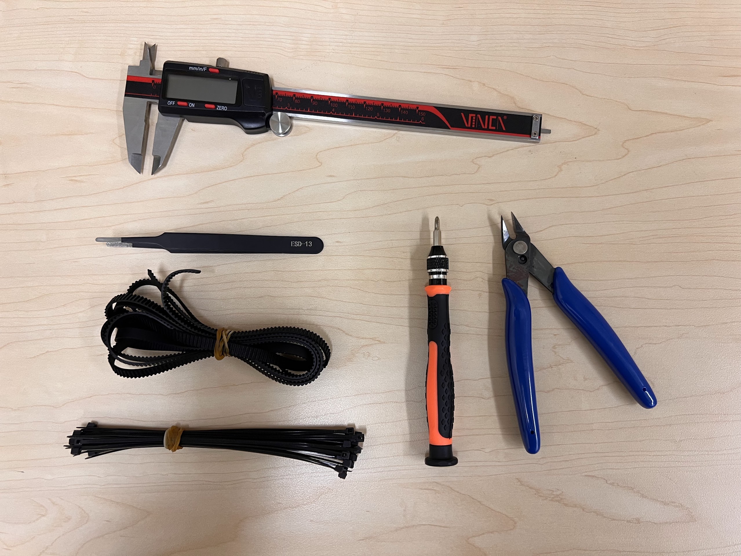
- Tweezer Kit
- 2 Pieces 8mm Diameter 450mm Length Rods
- Extra GT2 Timing Belt if necessary.
- Digital Vernier Calipers to check dimensions.
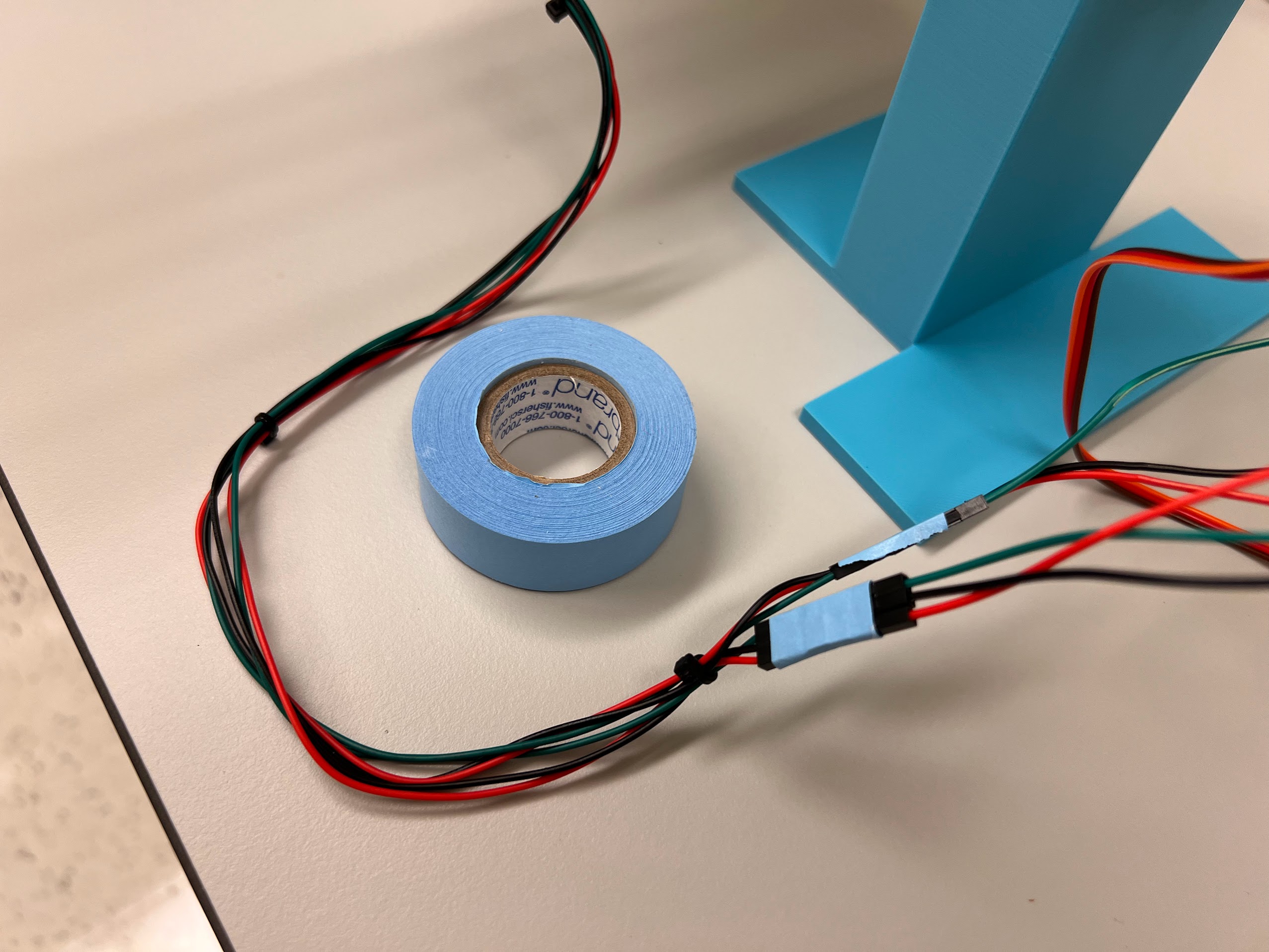
- Jumper Cables
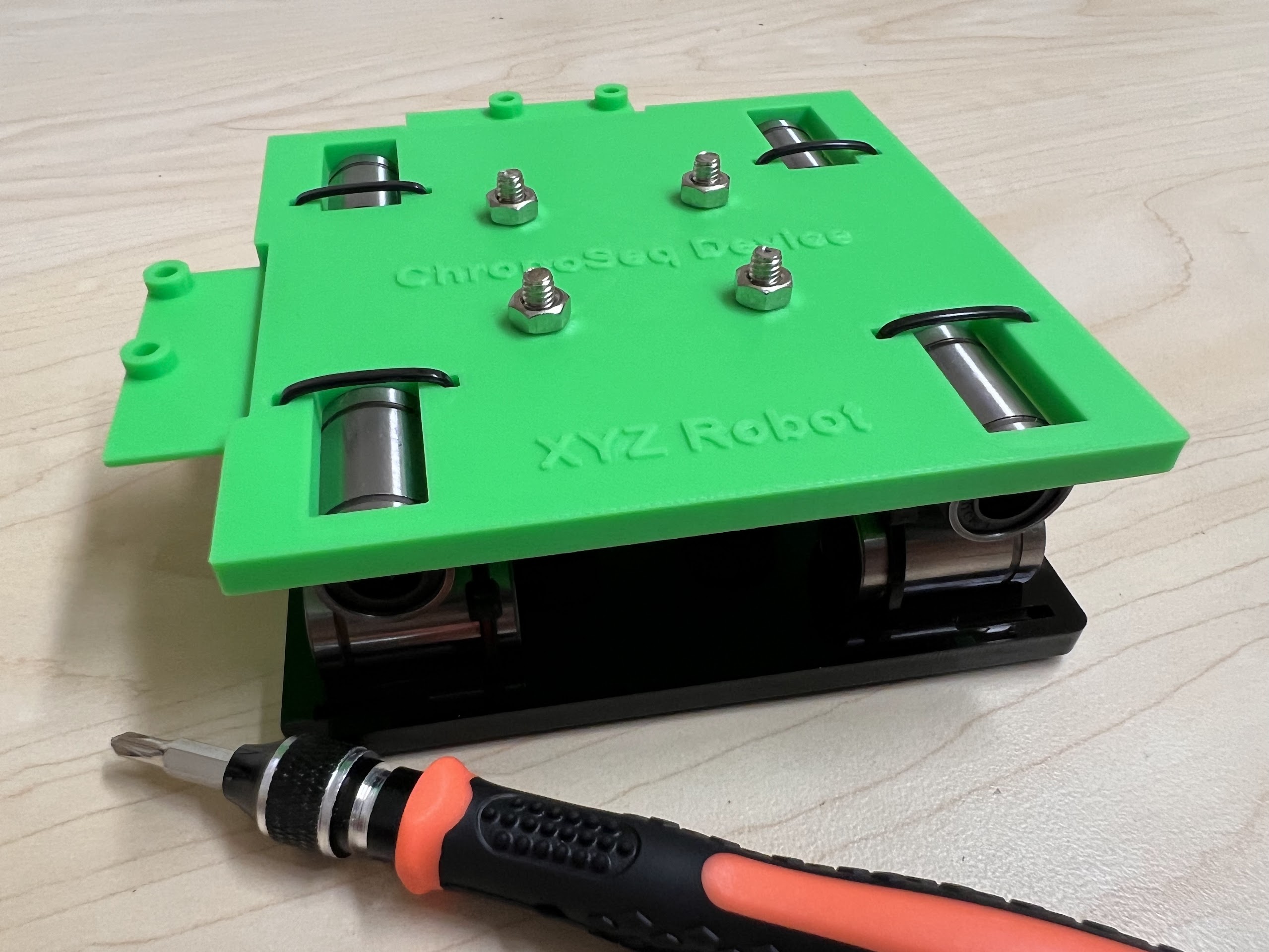
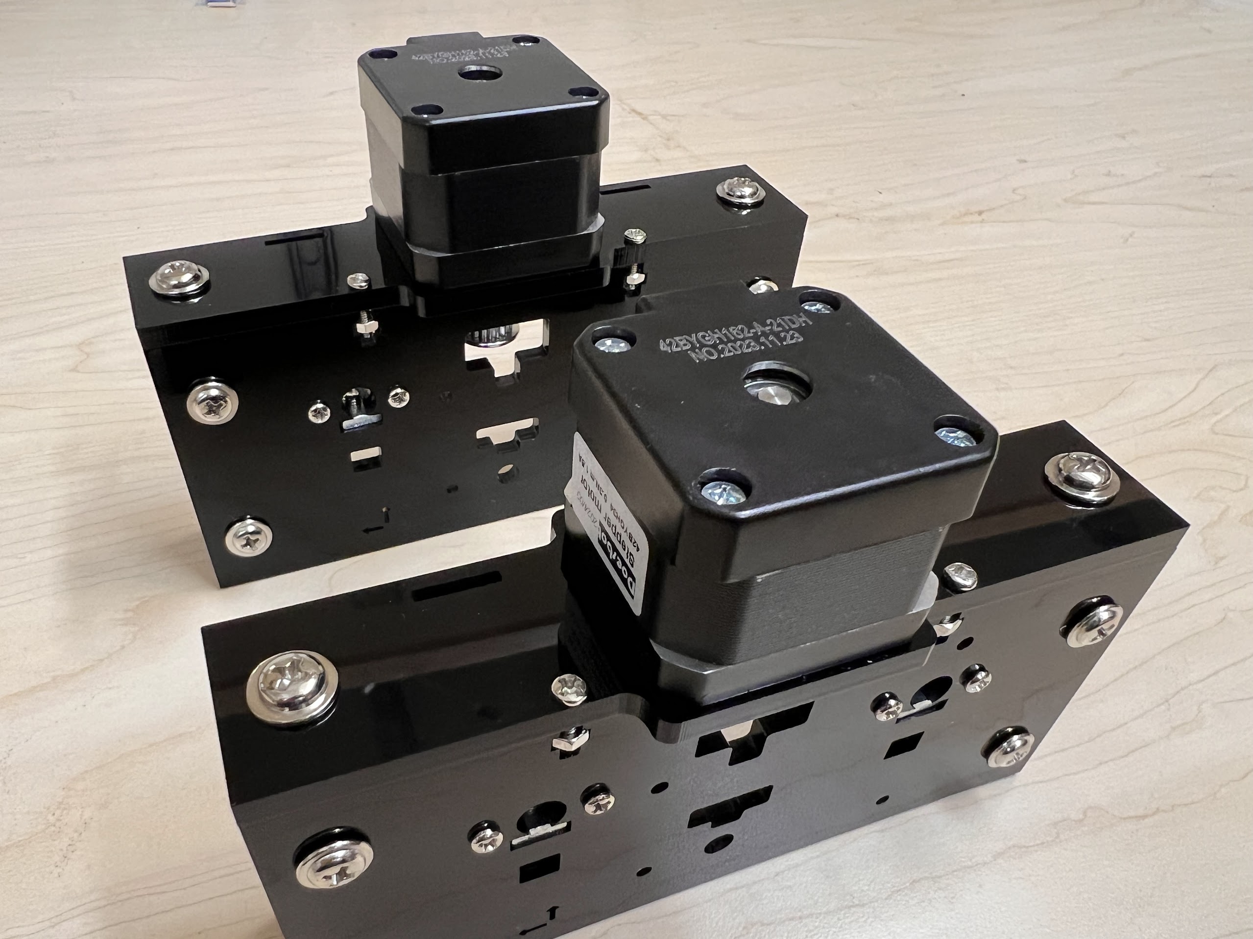
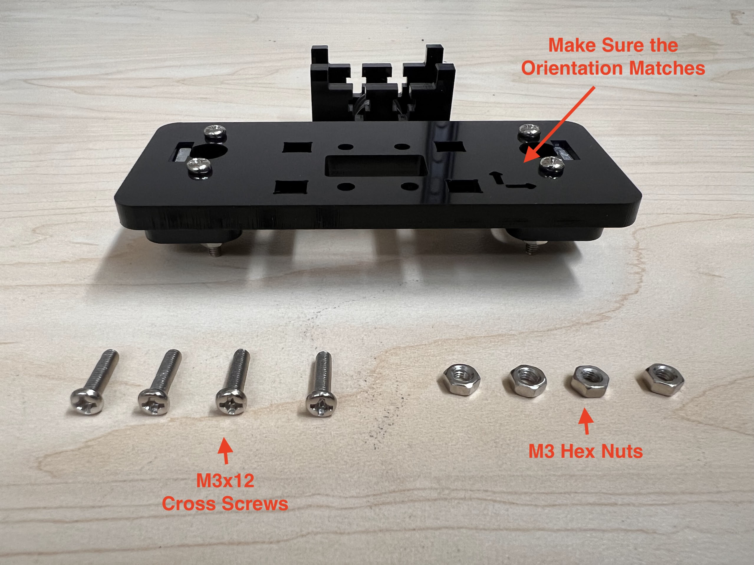
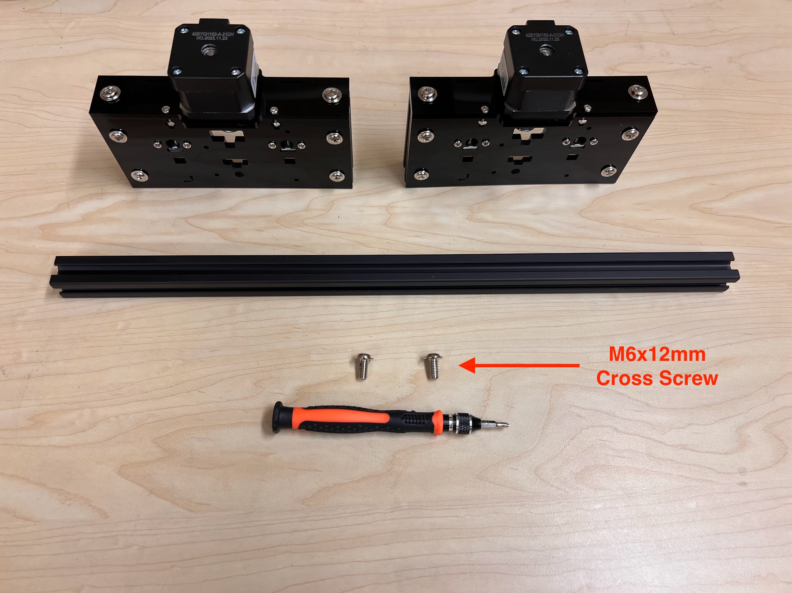
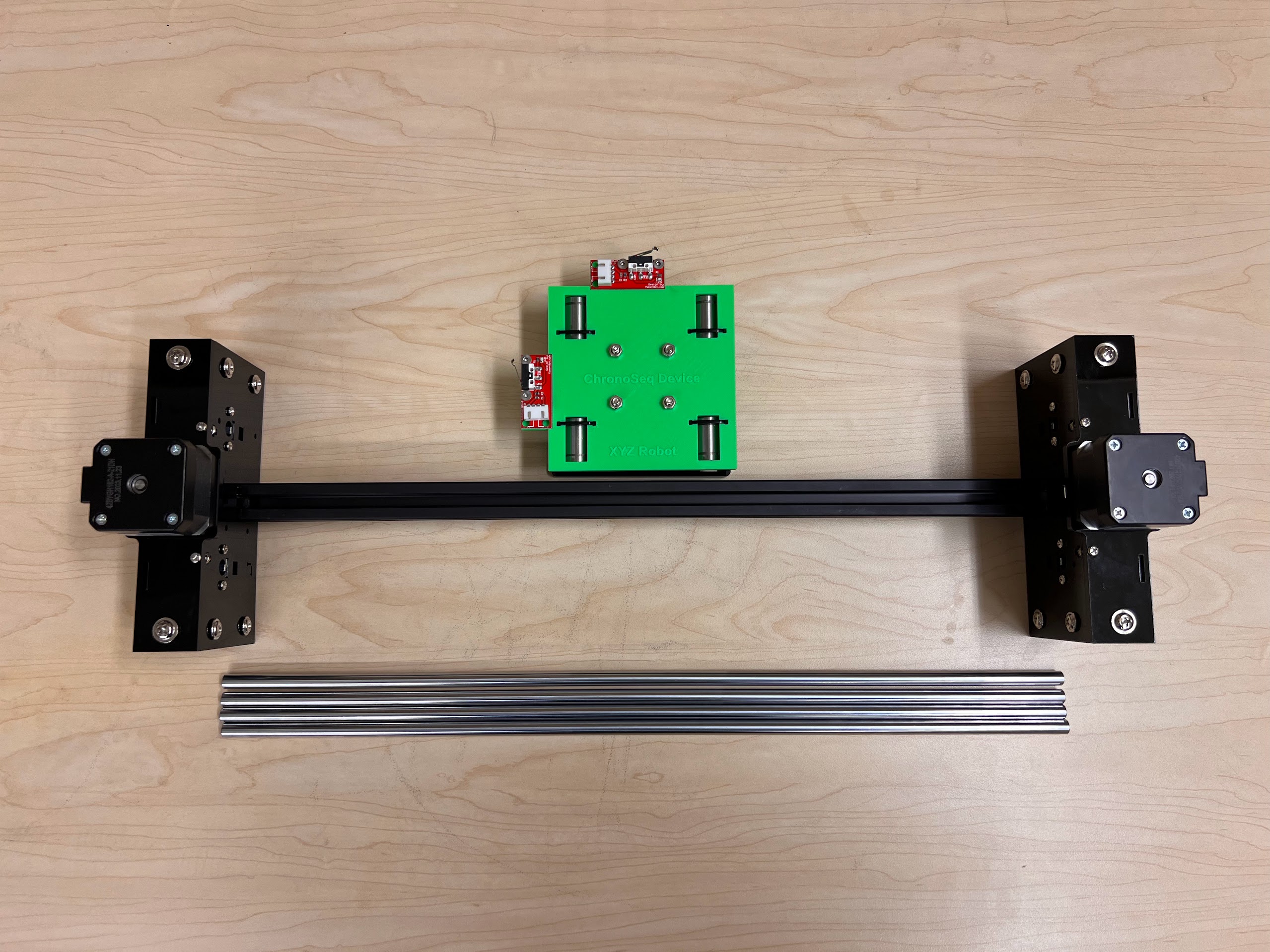
Assembling the Robot
Assembling the Centeral Cross Slide
- Instructions adapted from Original Doesbot assembly instructions.
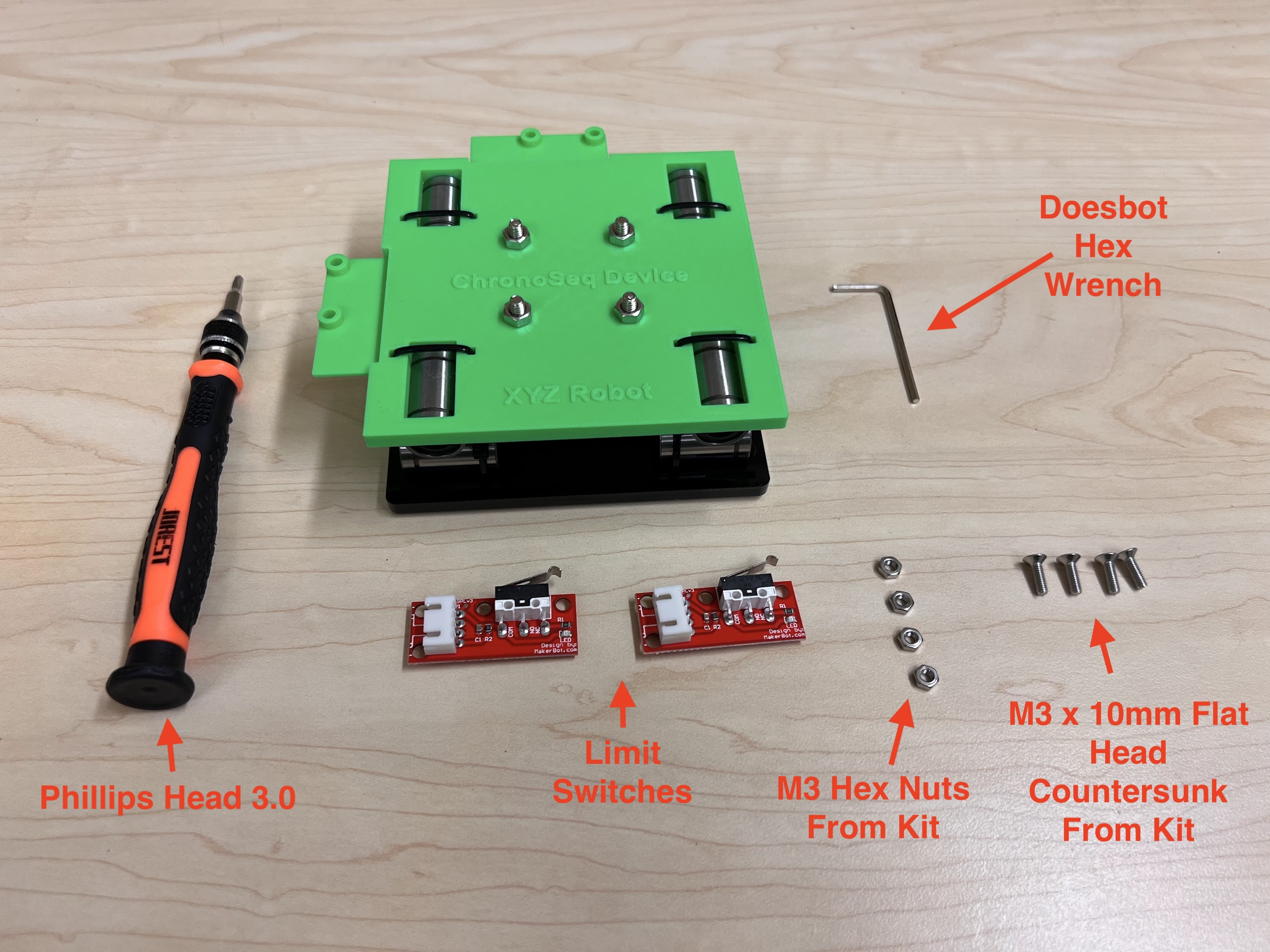
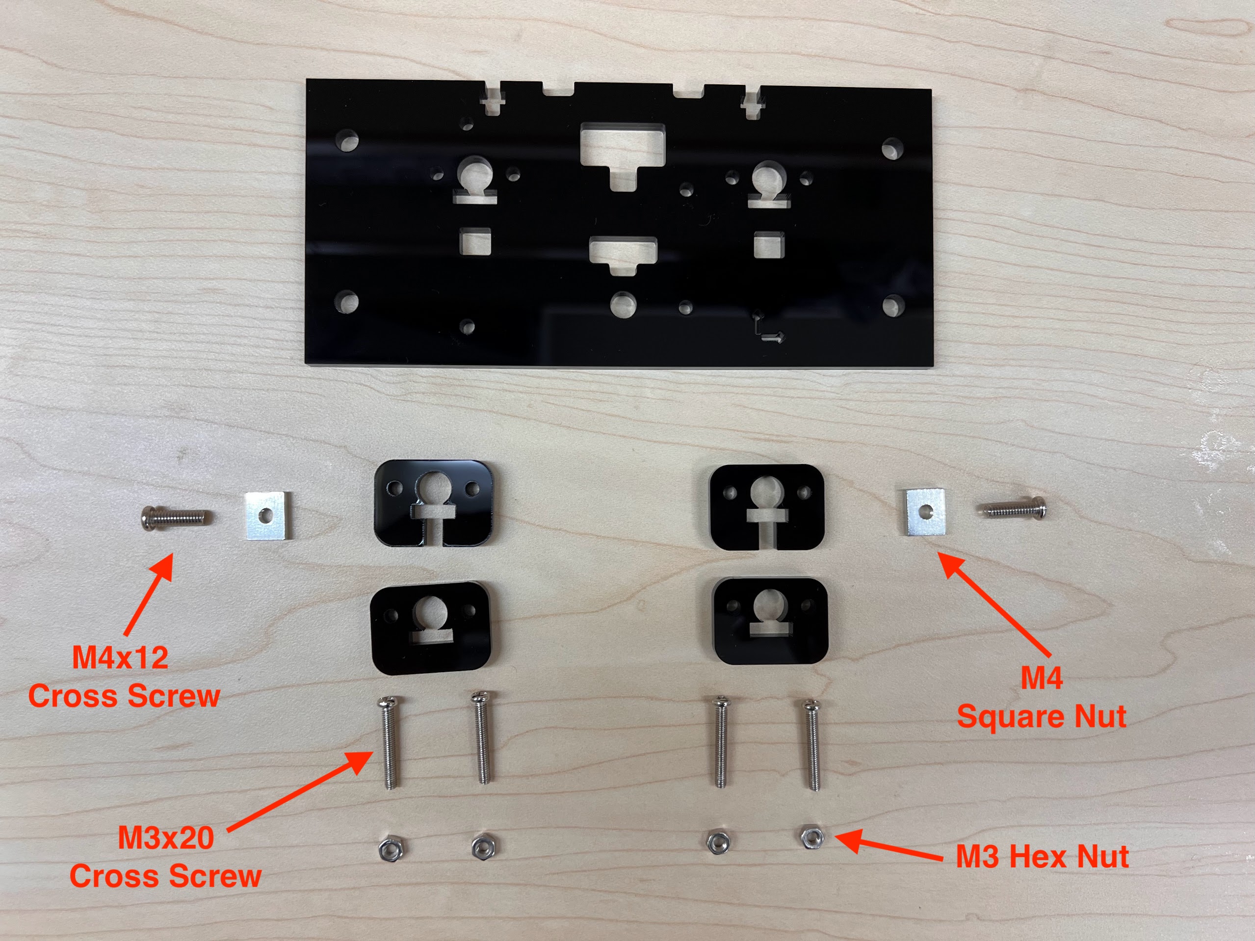
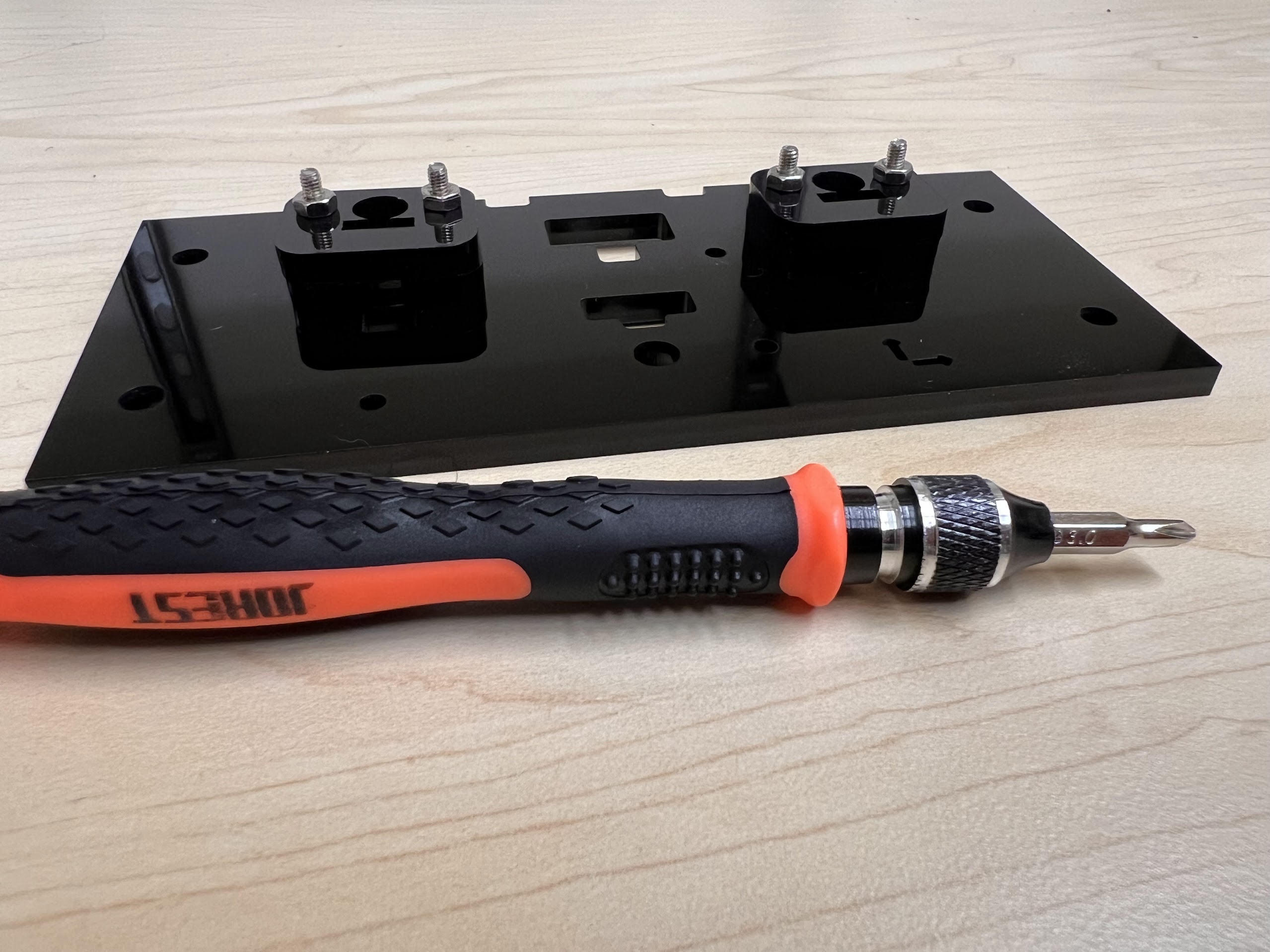
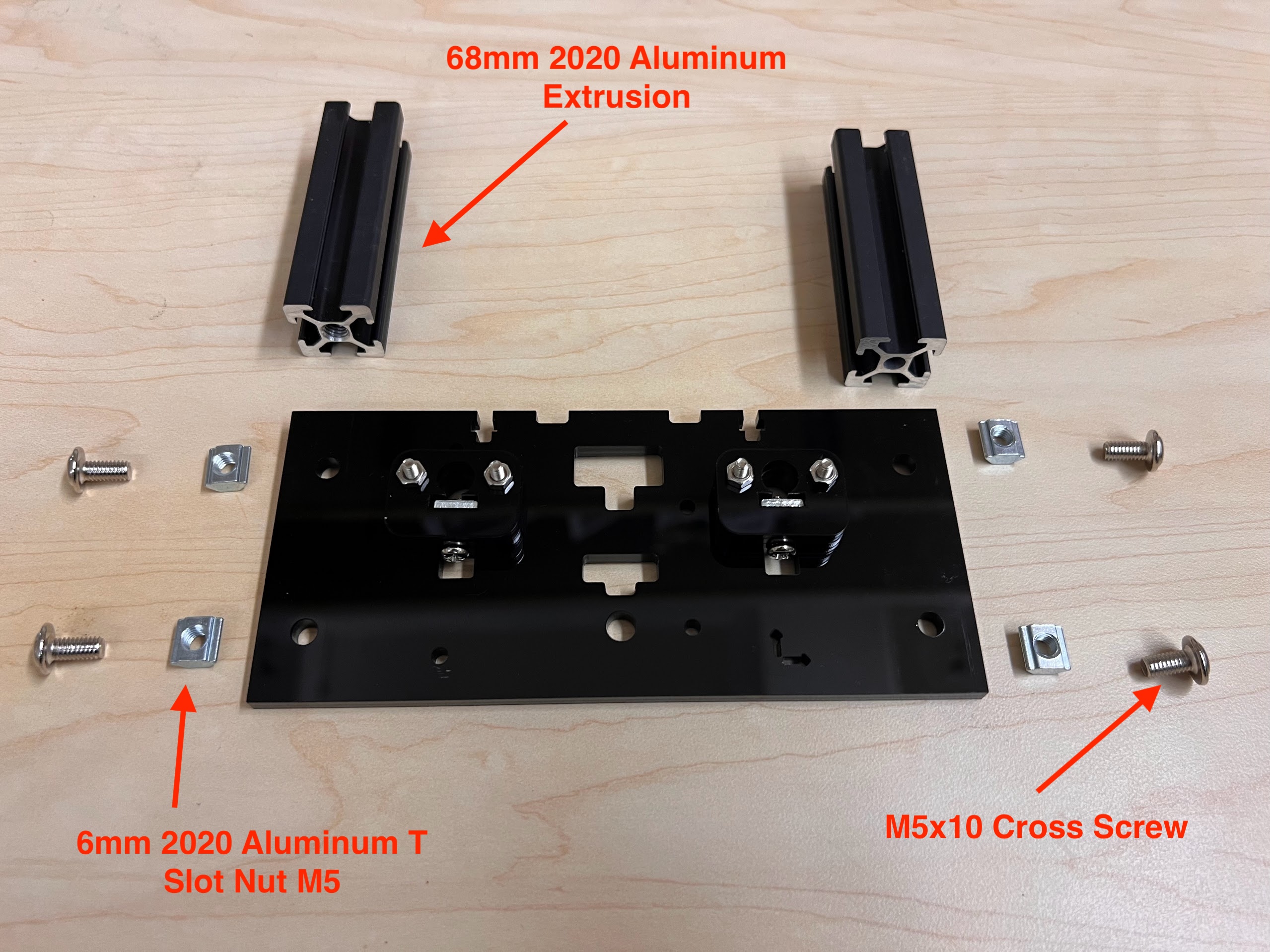
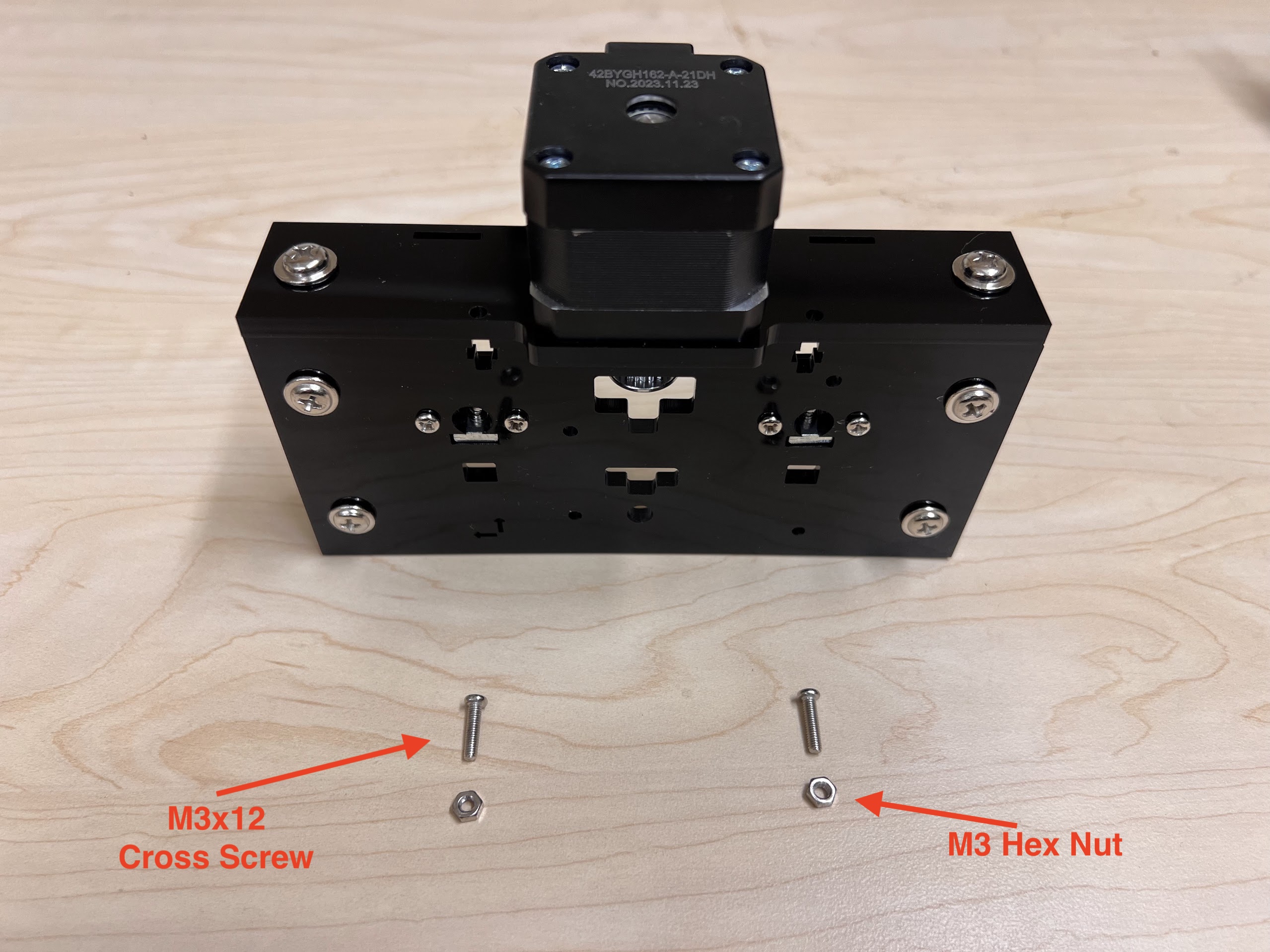
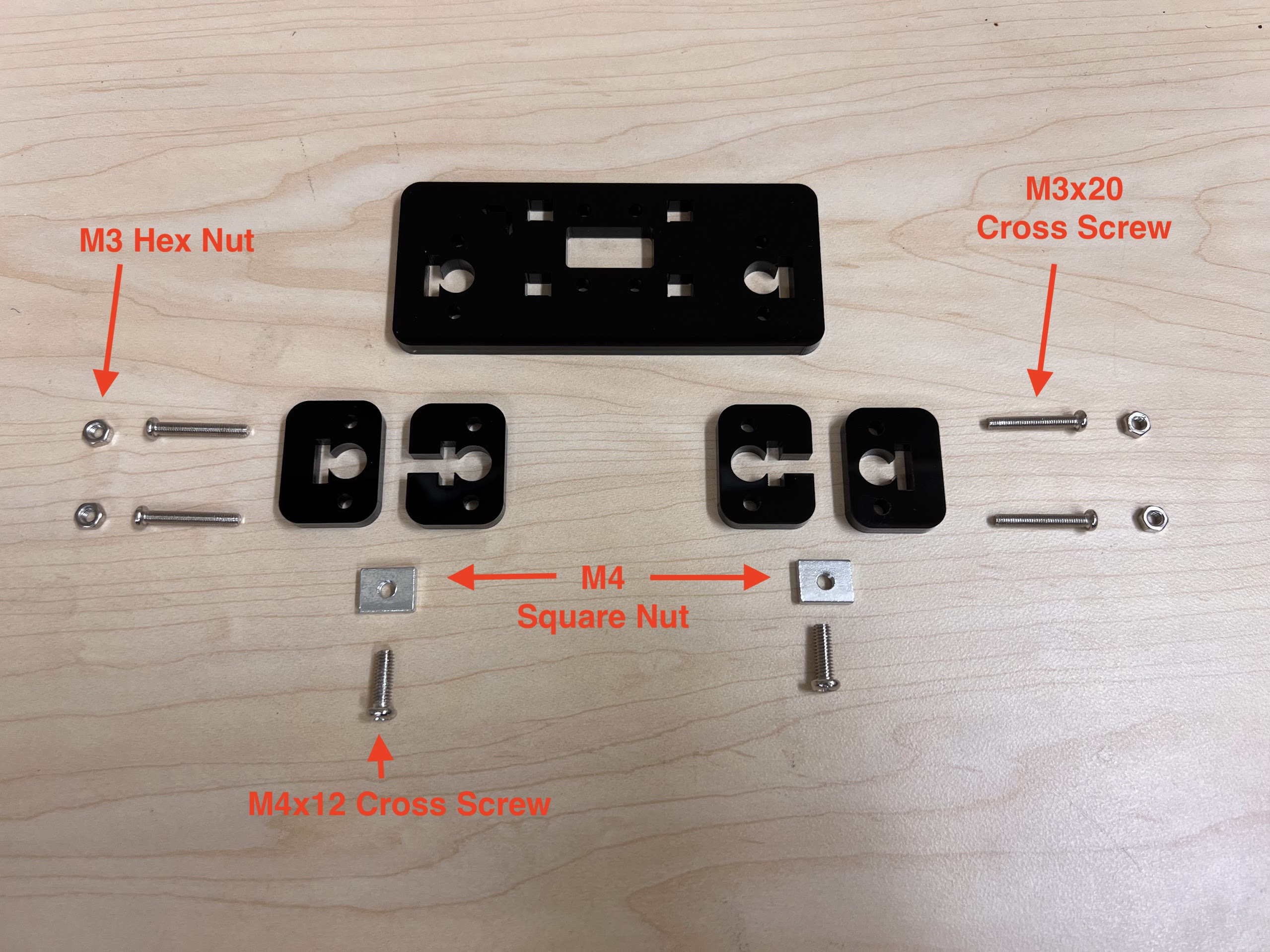
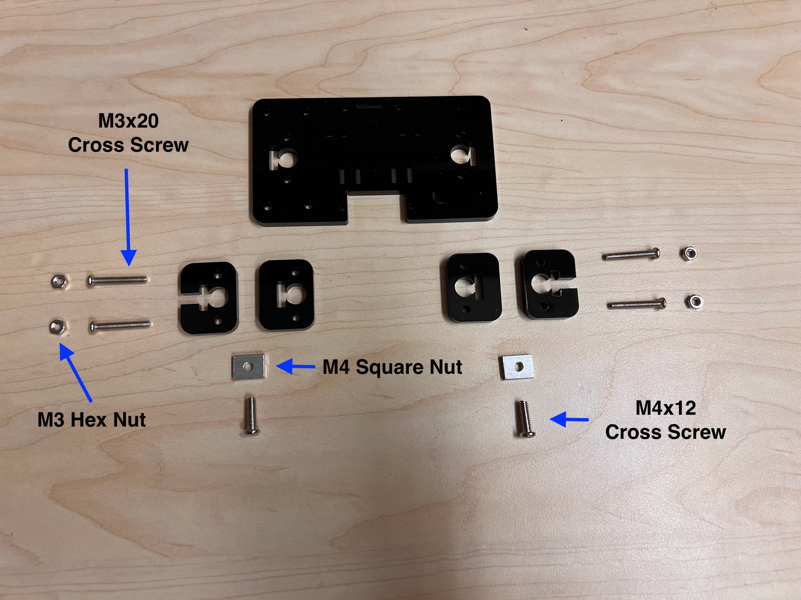
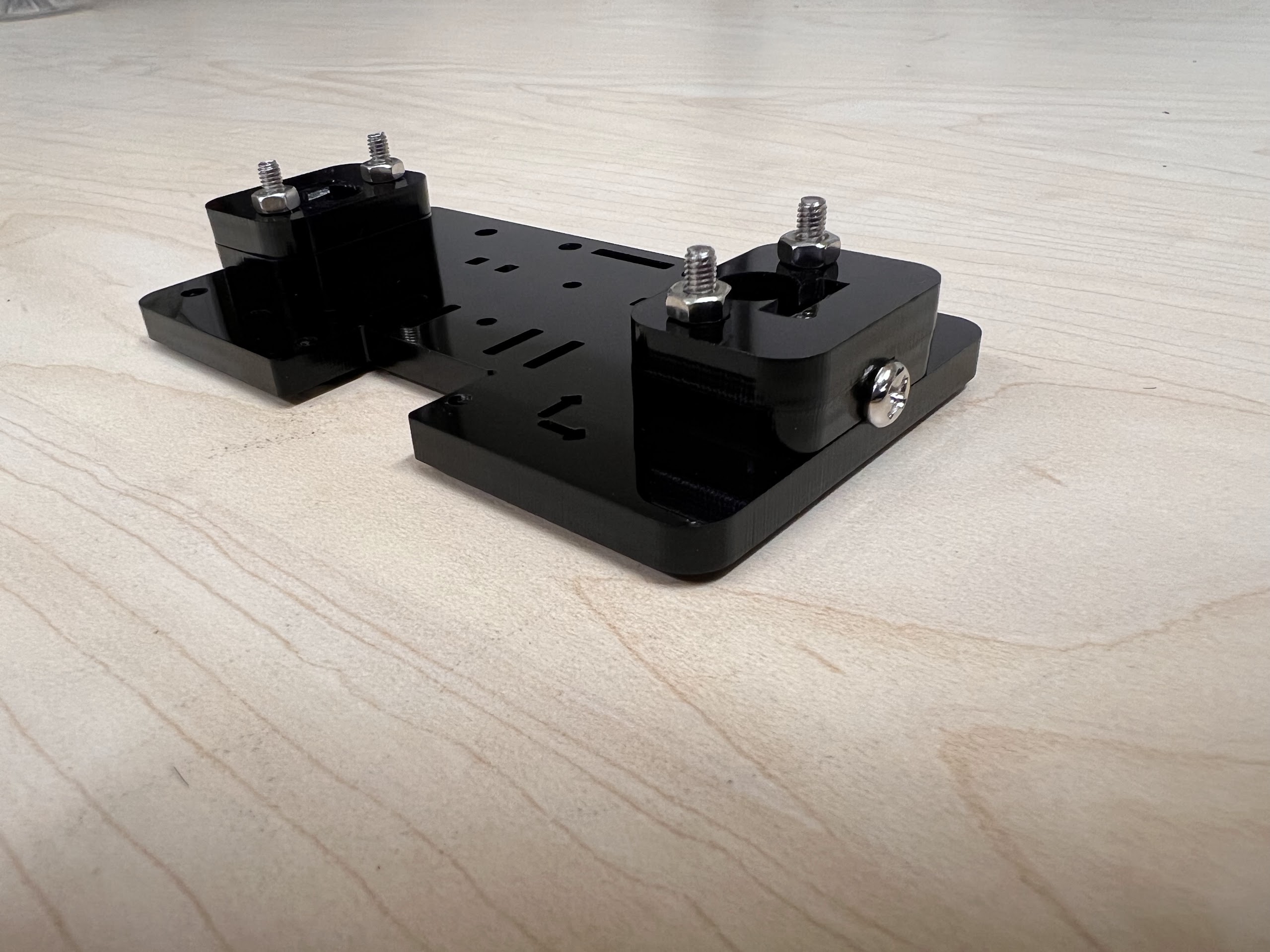
- You will need the following Parts for Assembling the Cross-Slide.
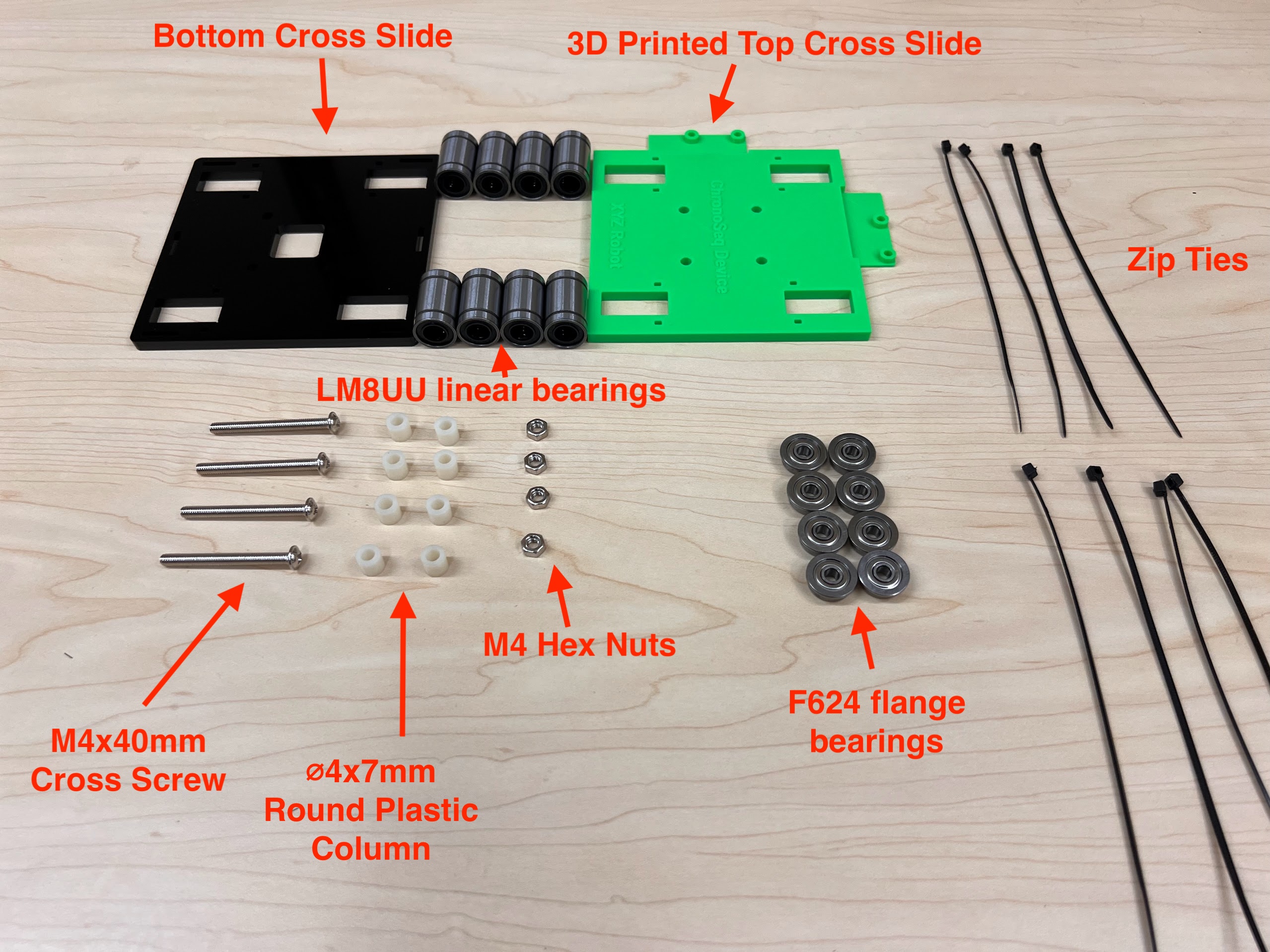
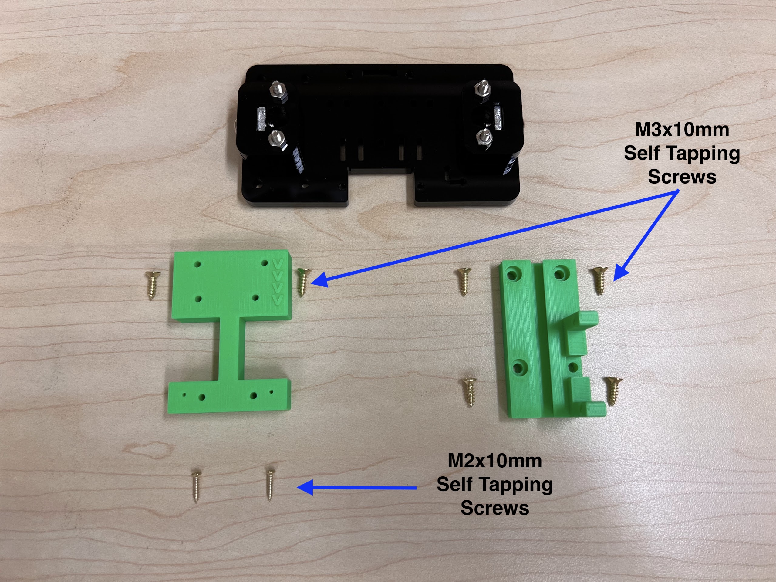
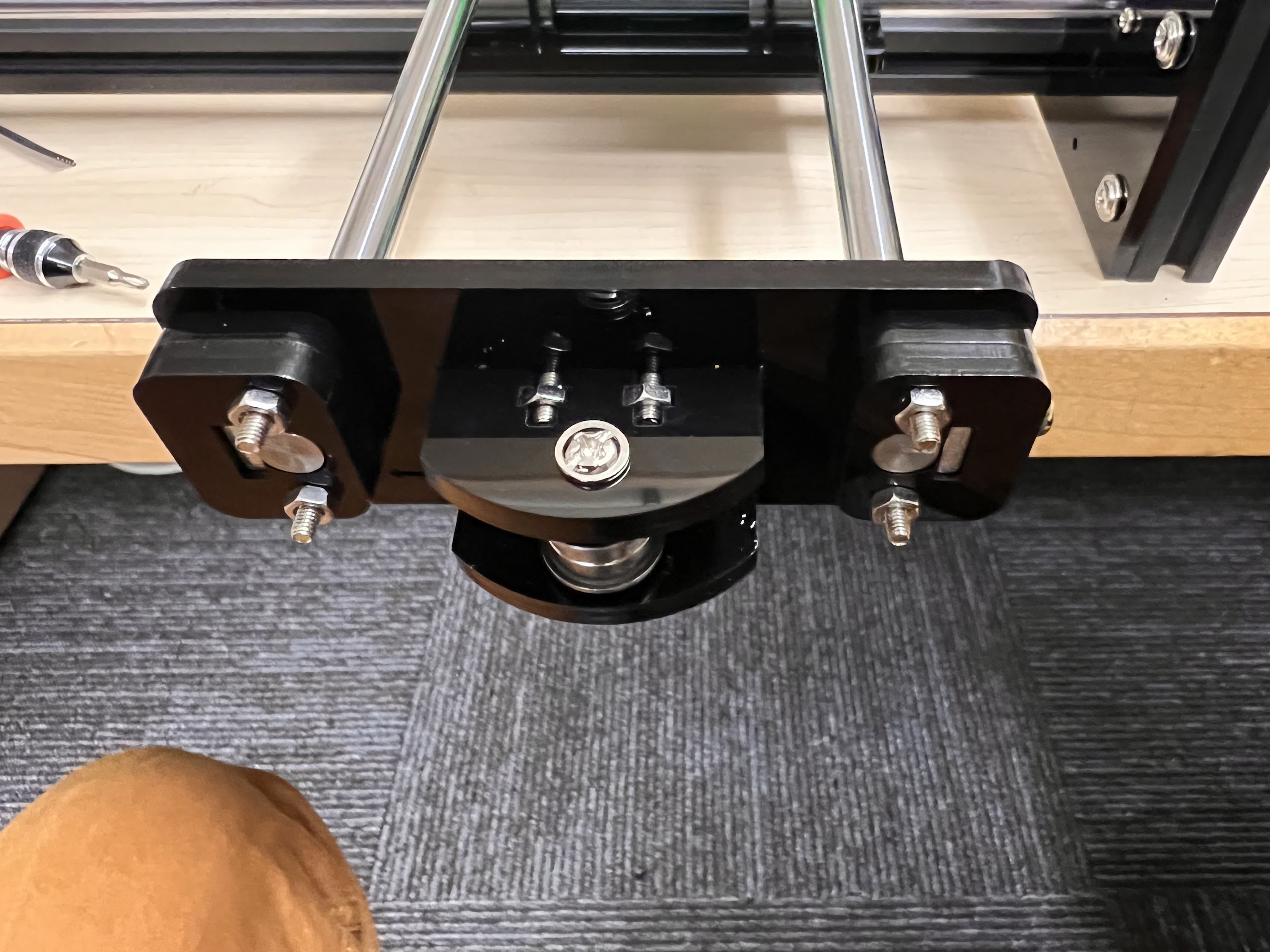
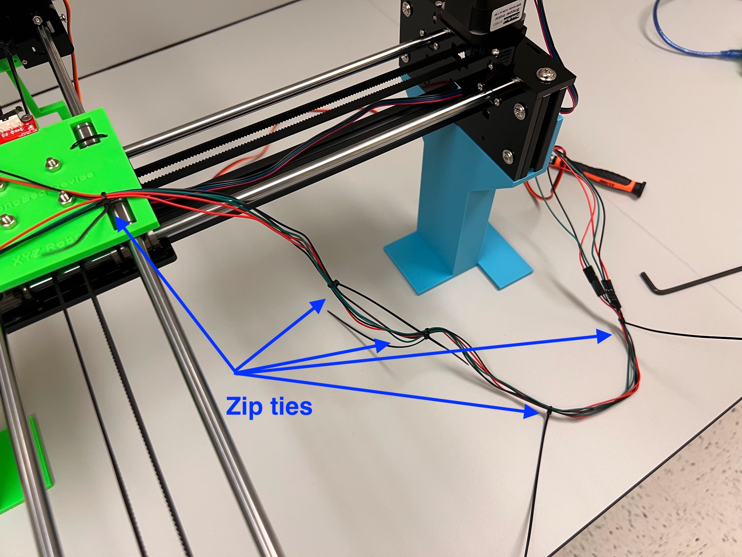
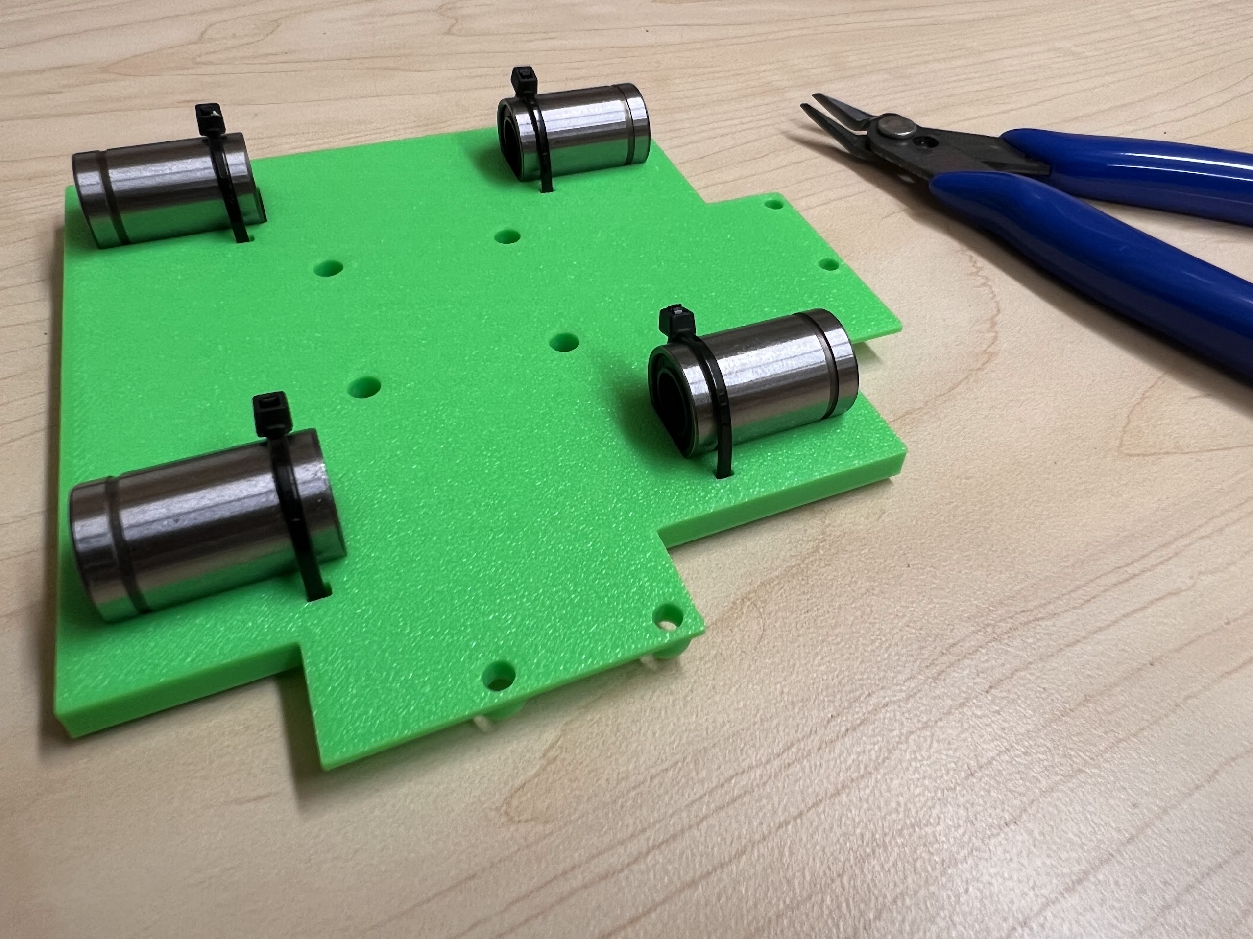
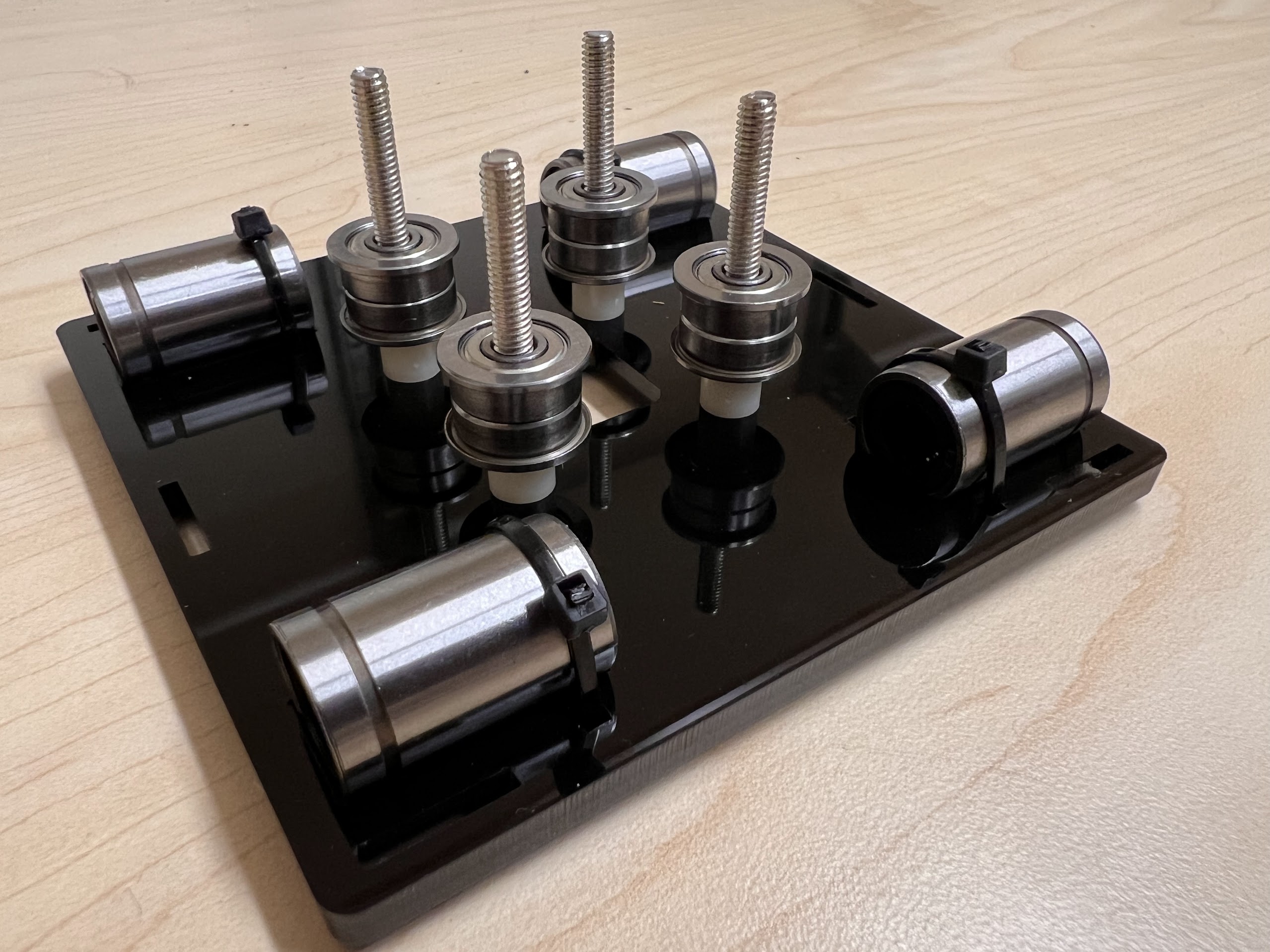
- Using the Zip-Ties Secure the Linear Bearings to the Bottom Cross Slide.
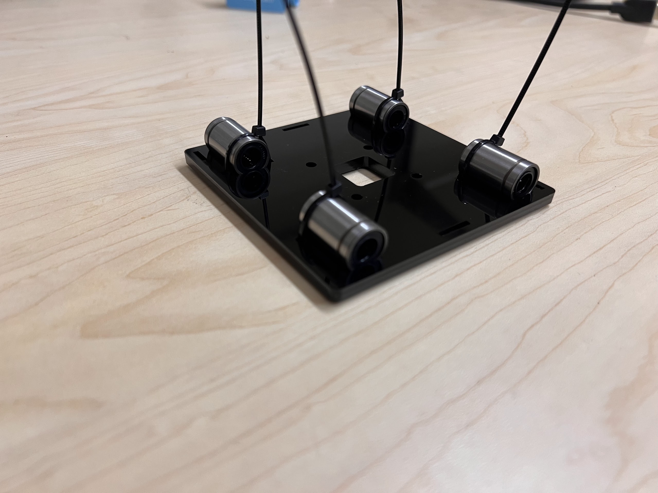
- Using the Cutters from the 3D Printing Accessories Kit, cut the ends of the Zip-Ties.
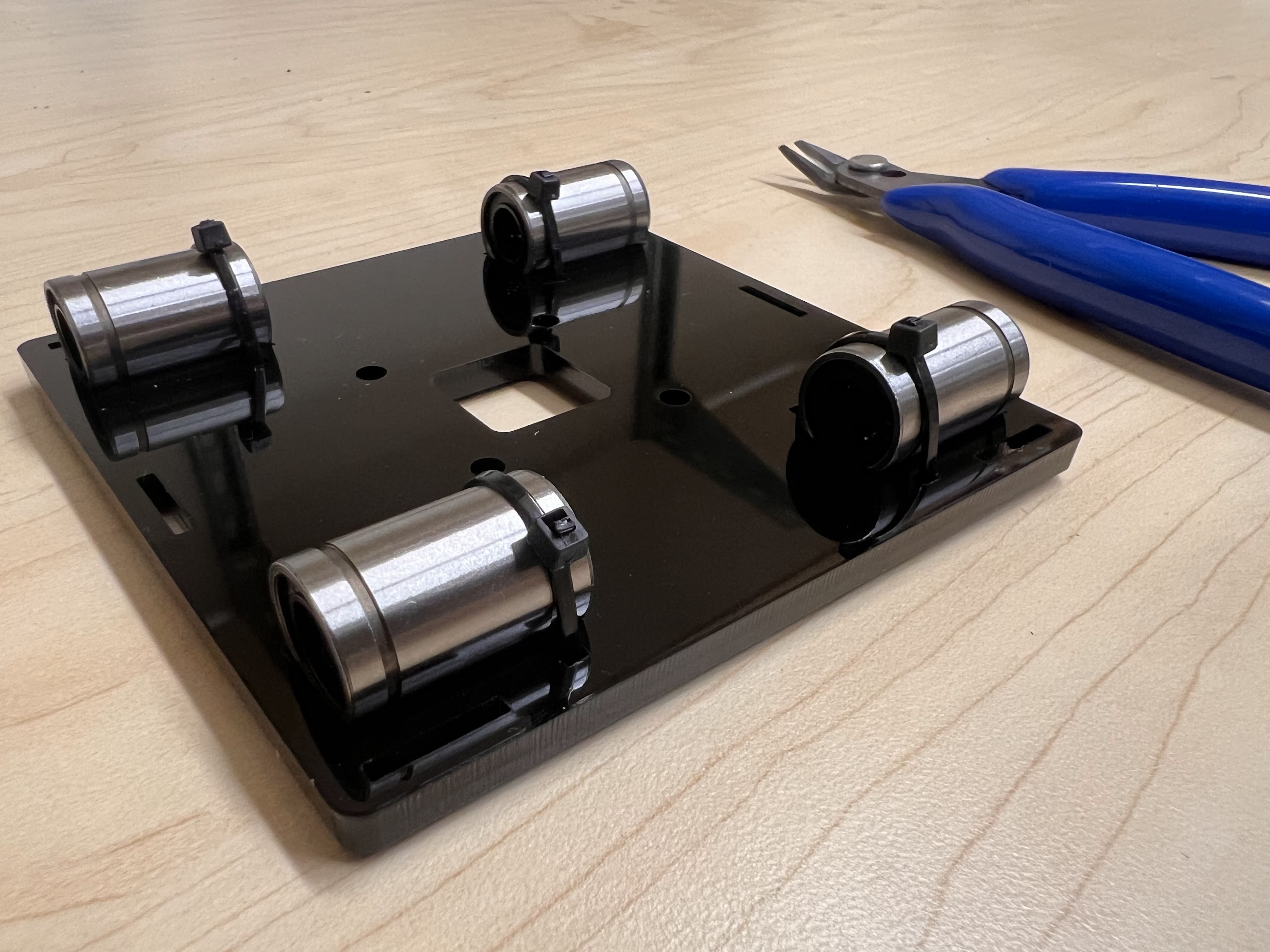
- Do the same for the 3D Printed Top Cross Slide.
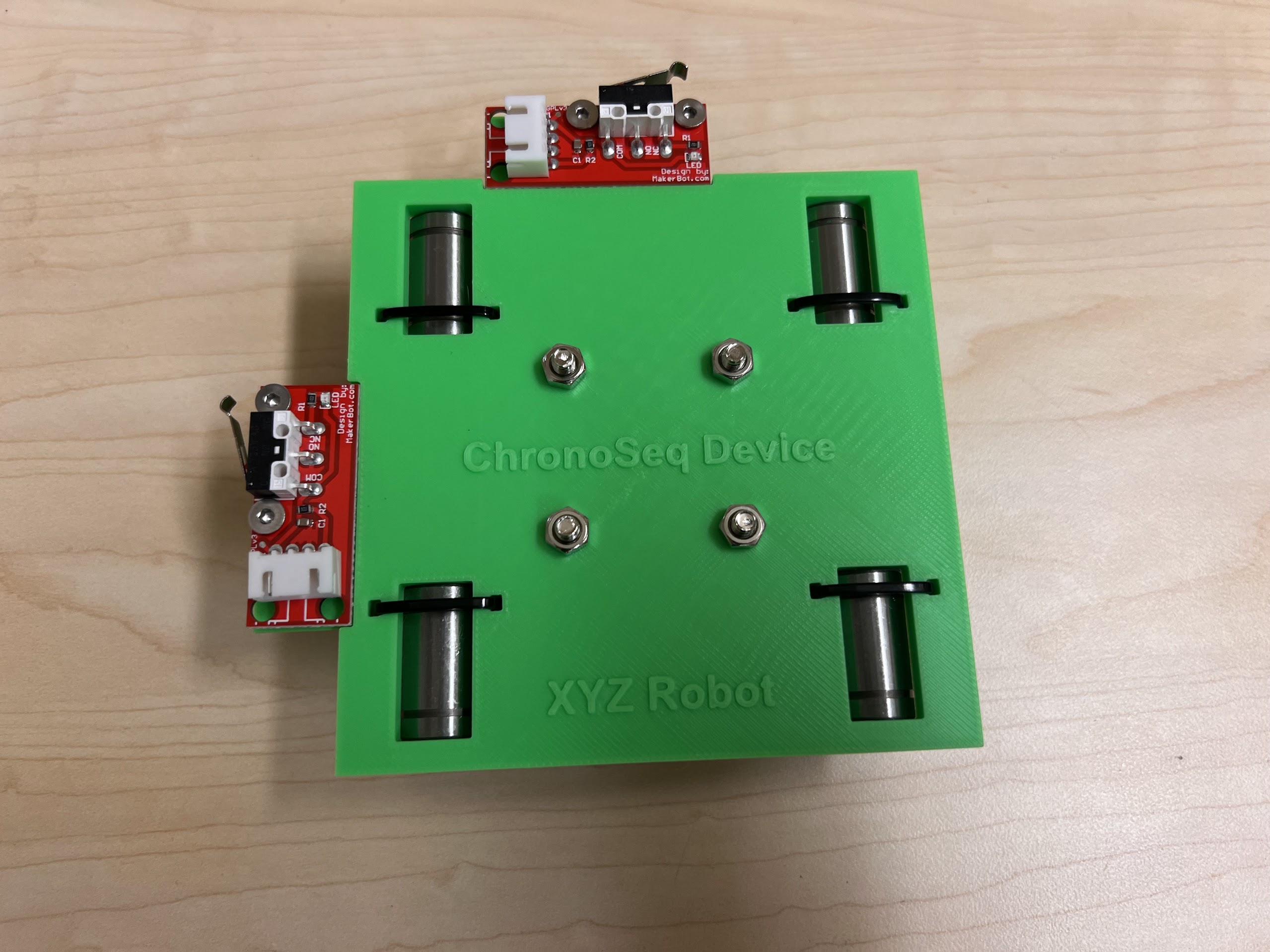
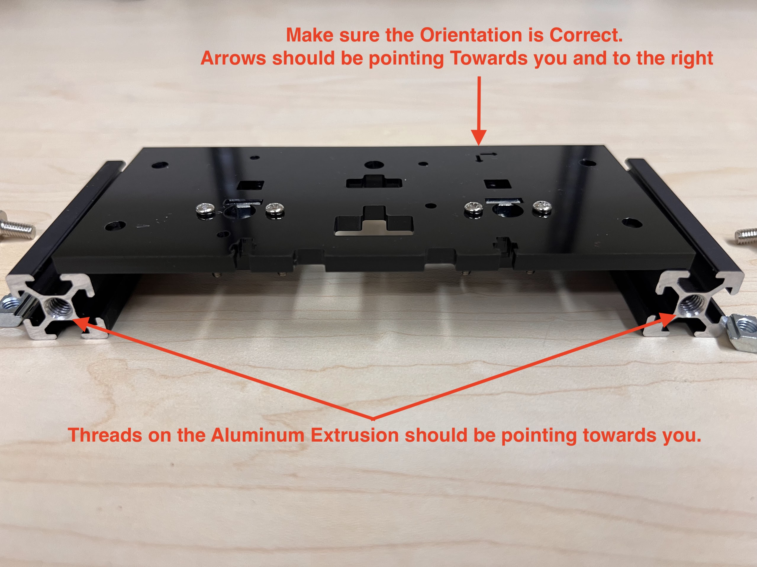
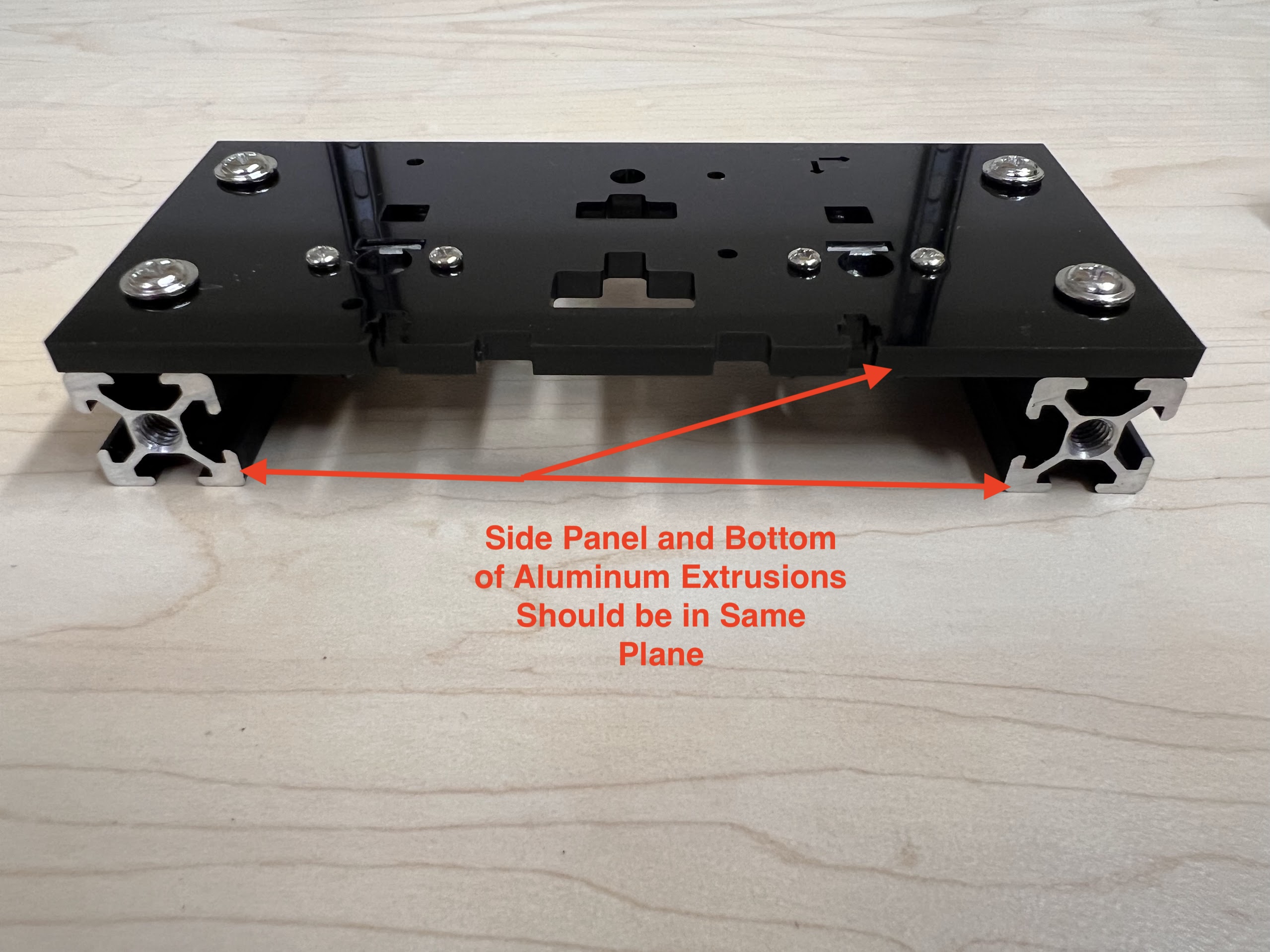
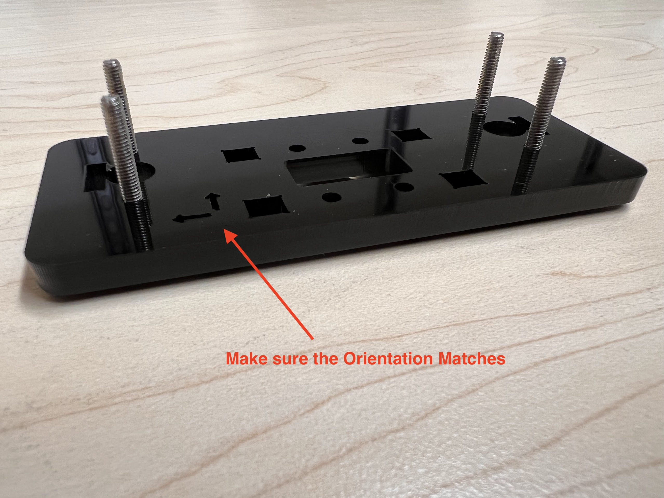
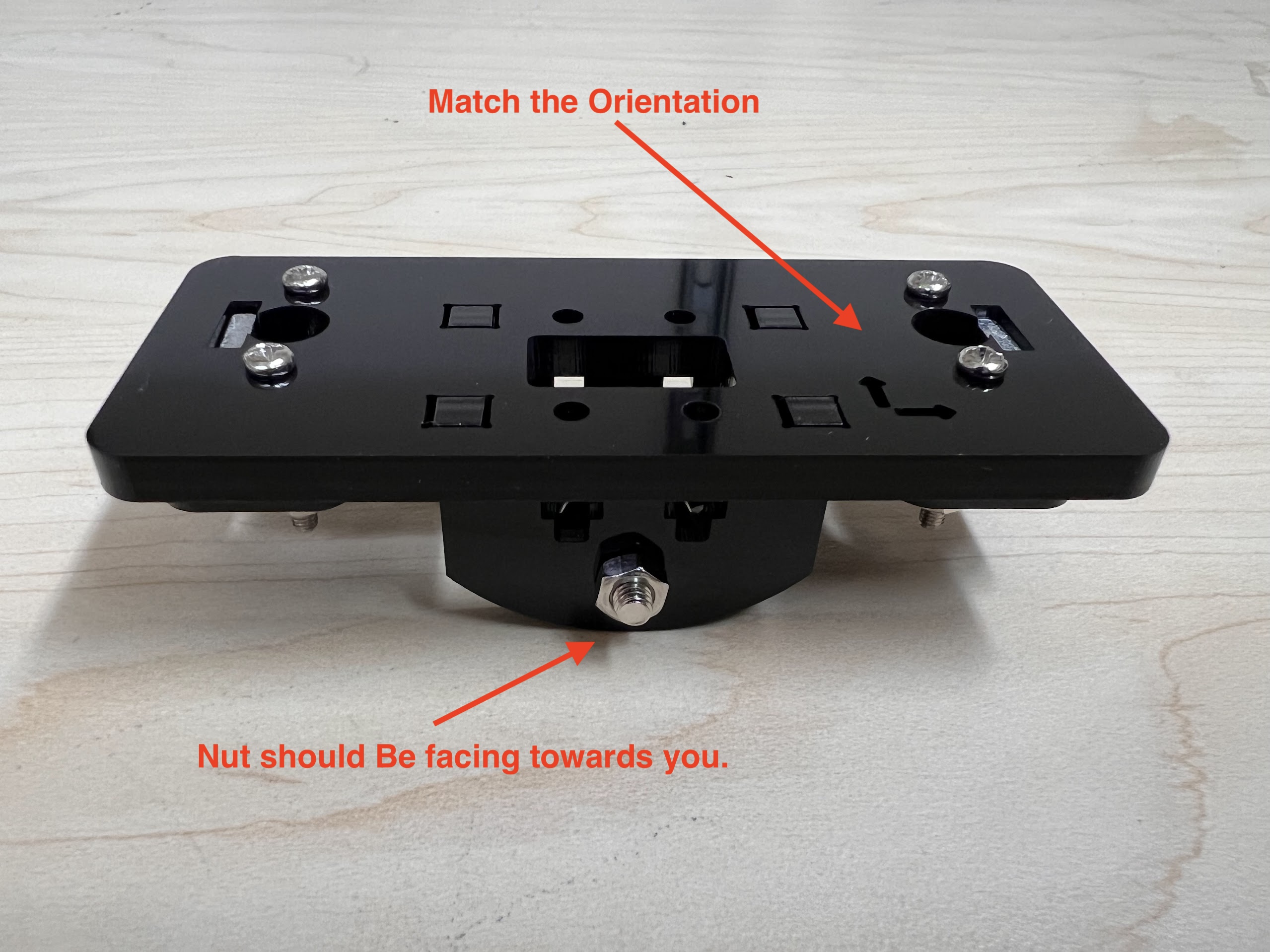
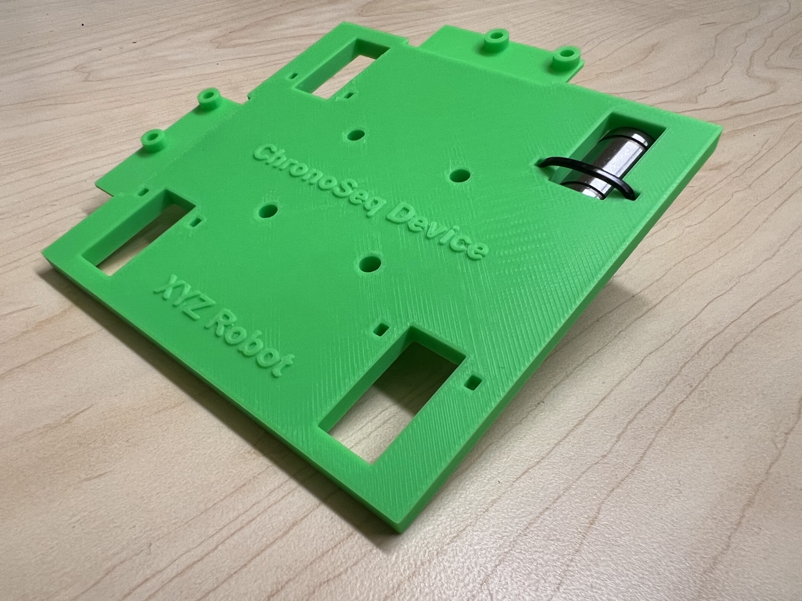
- Make sure the orientation of the Linear Bearings is Correct.
- The Text should be on the Opposite Side to the Linear Bearings.
| Secure the Linear Bearings using Zip-Ties | 3D Printed Text Should be on the Opposite Side |
|---|---|
 |
 |
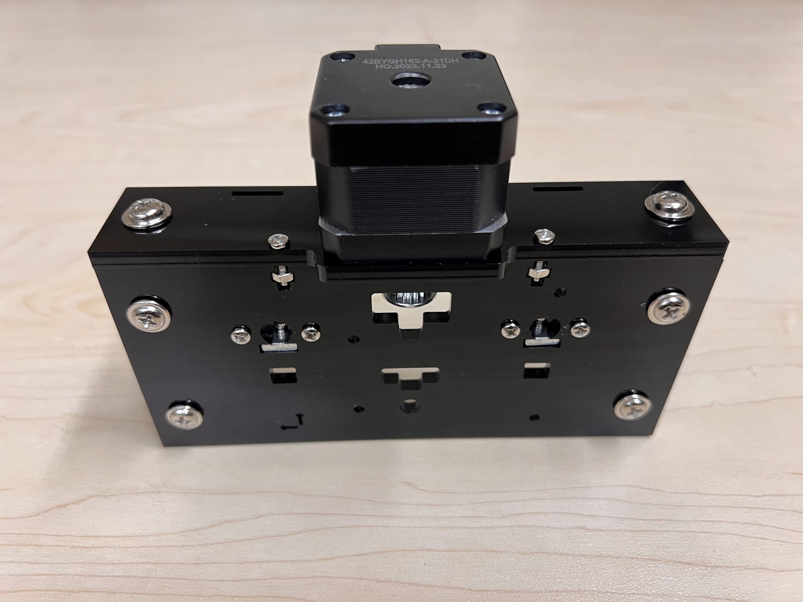
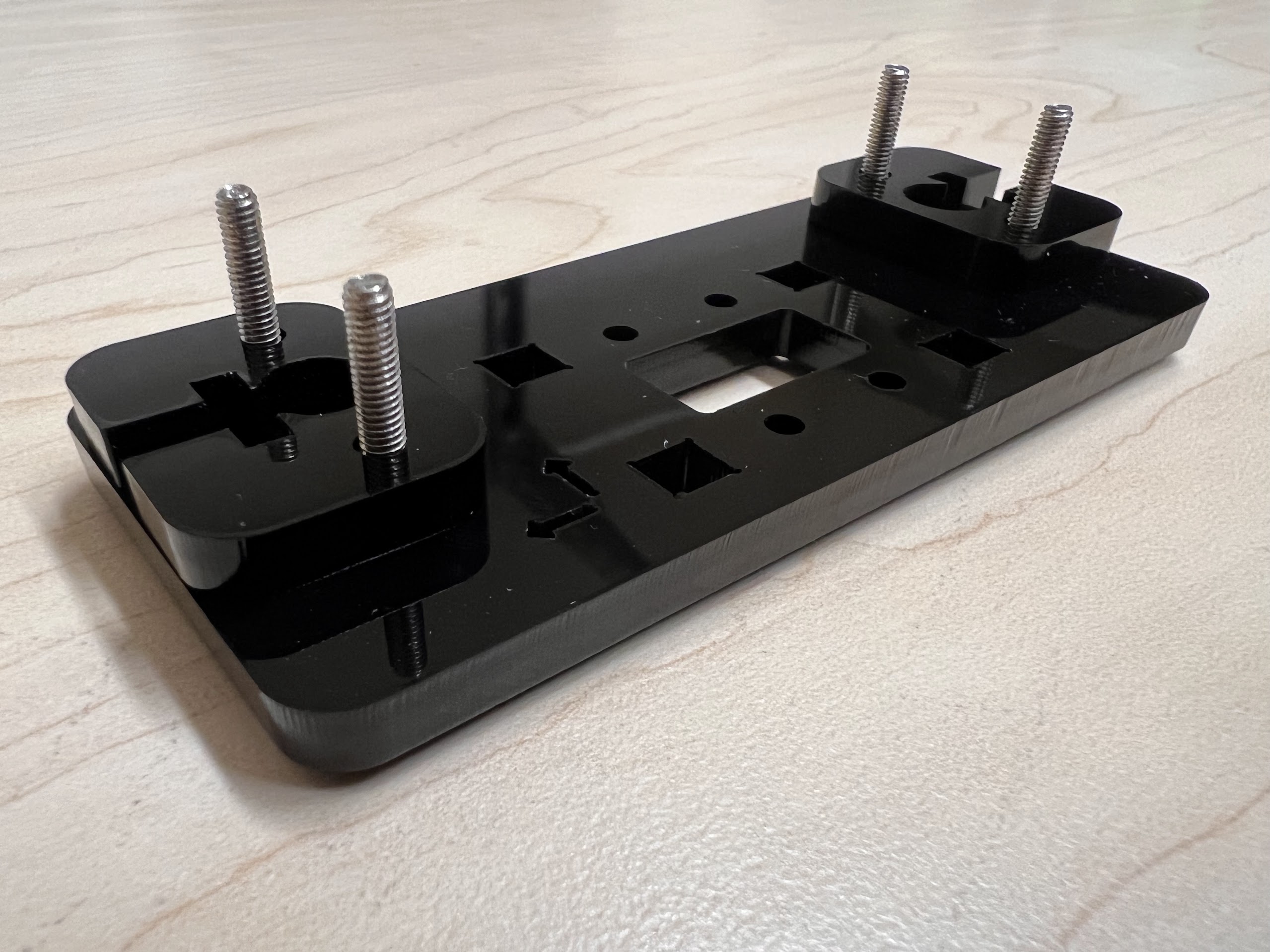
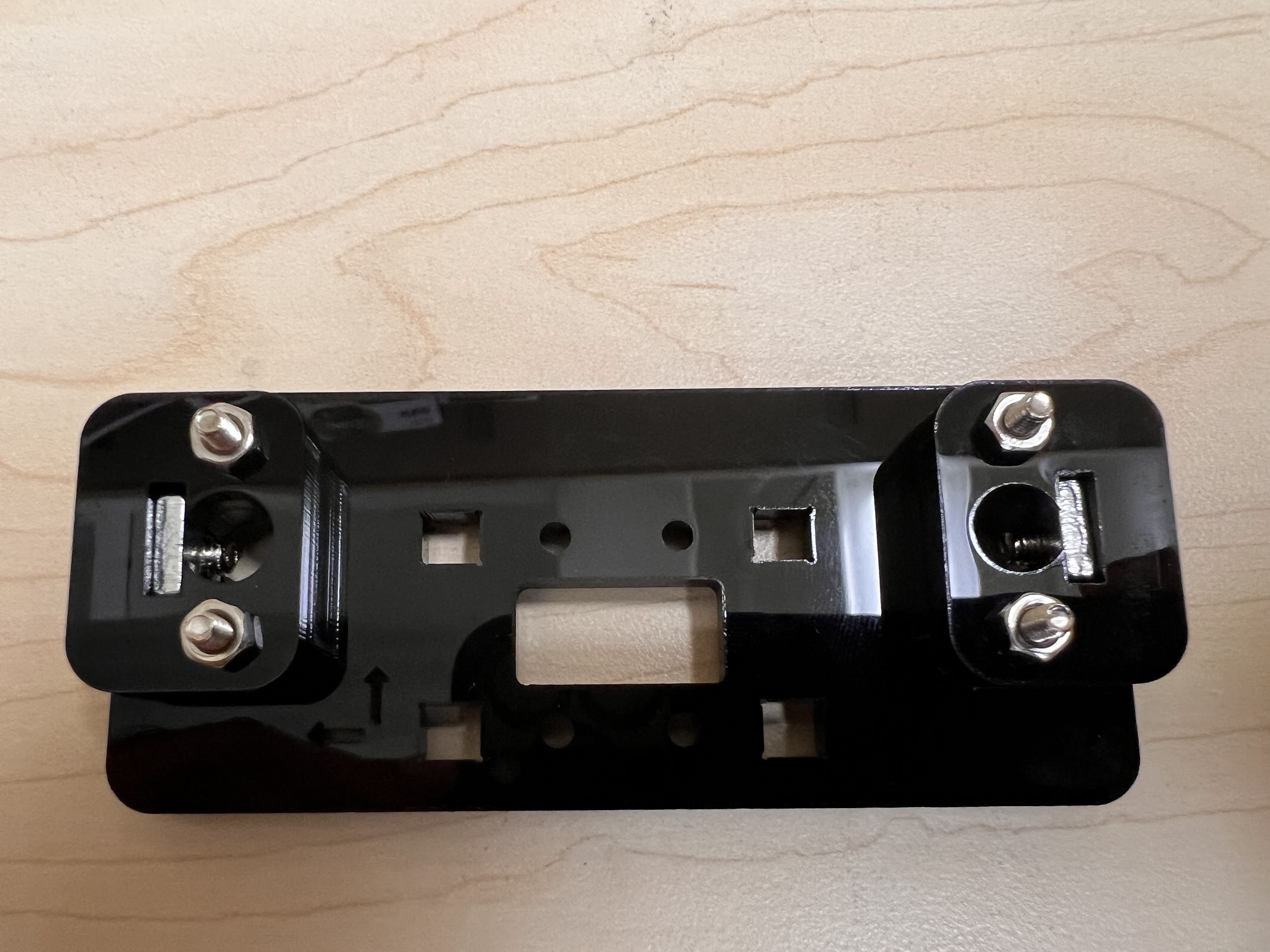
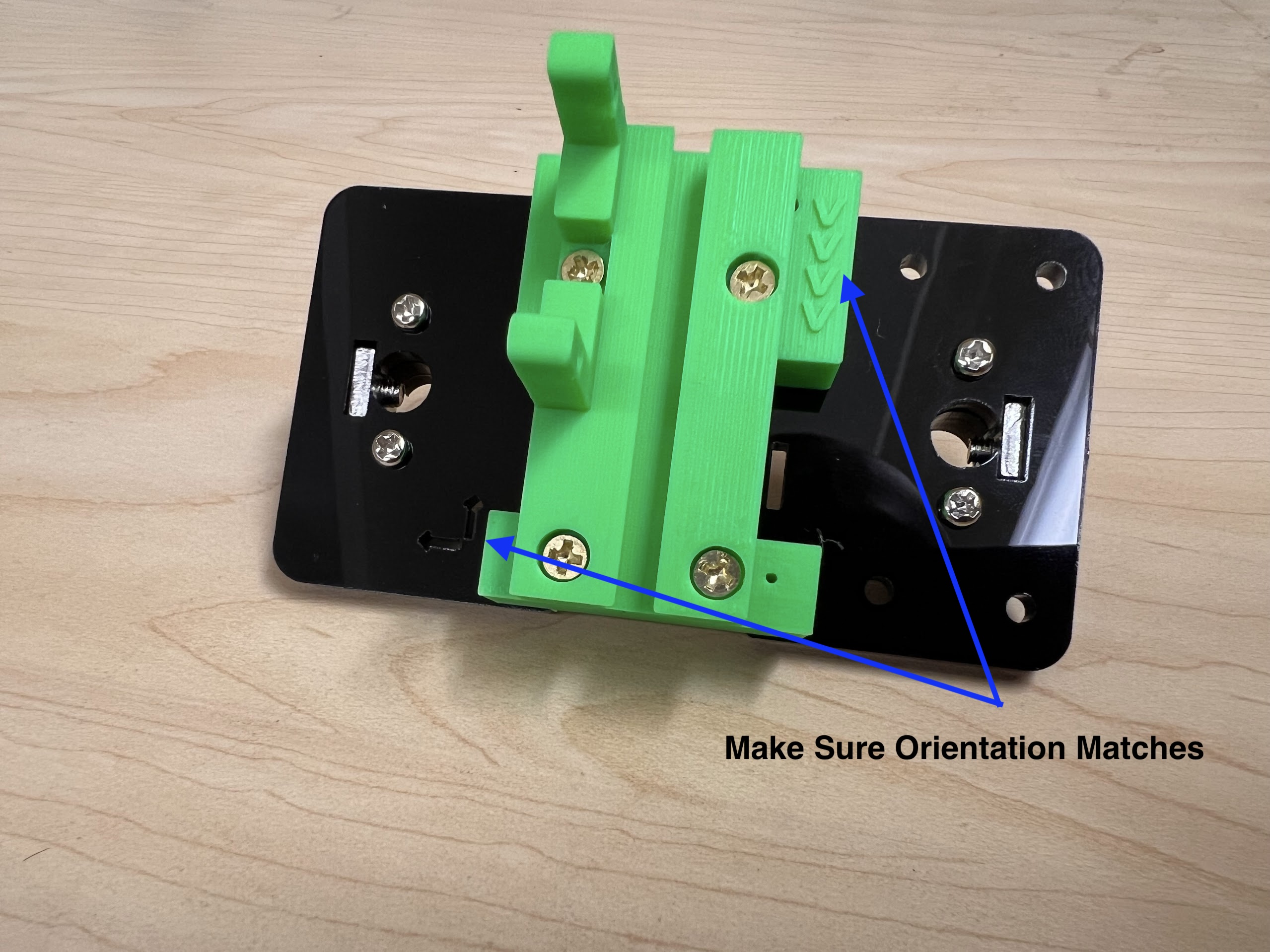
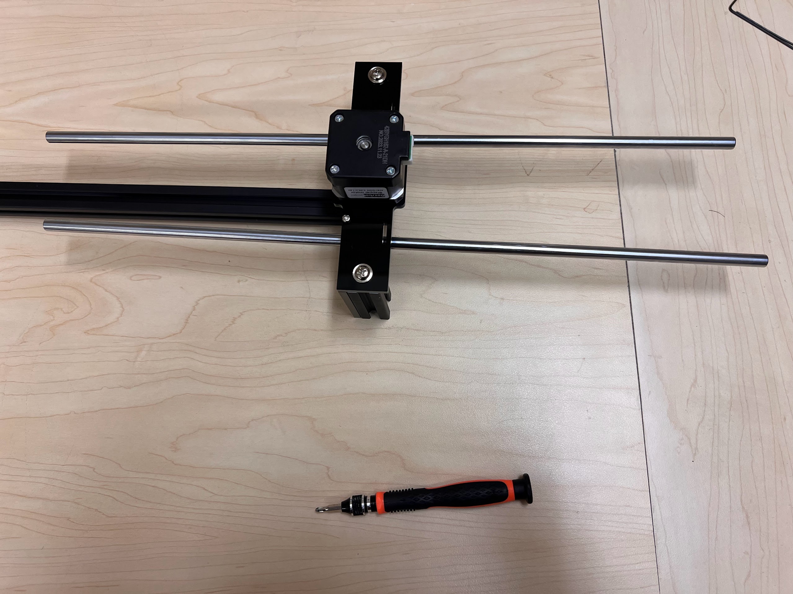
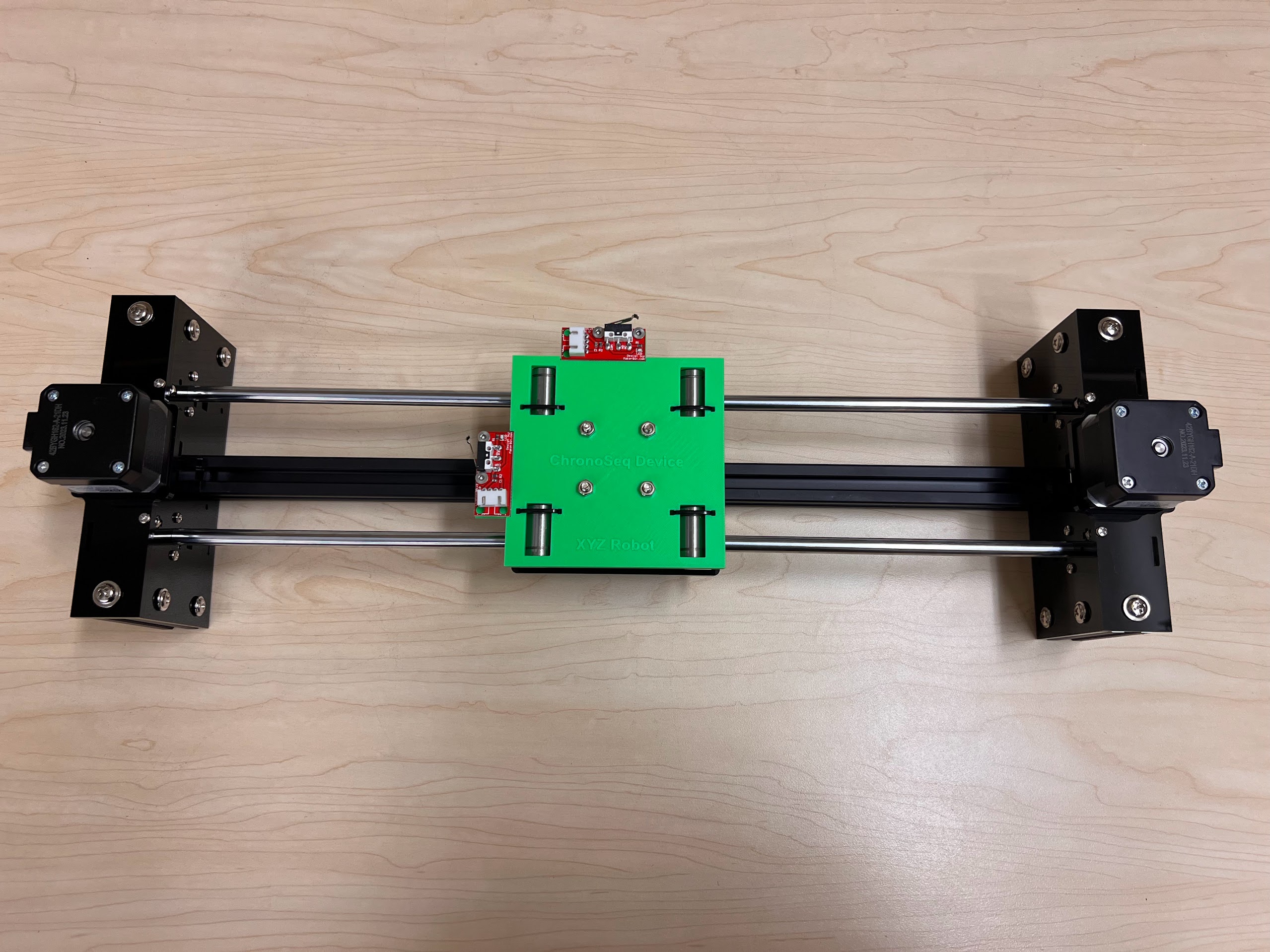
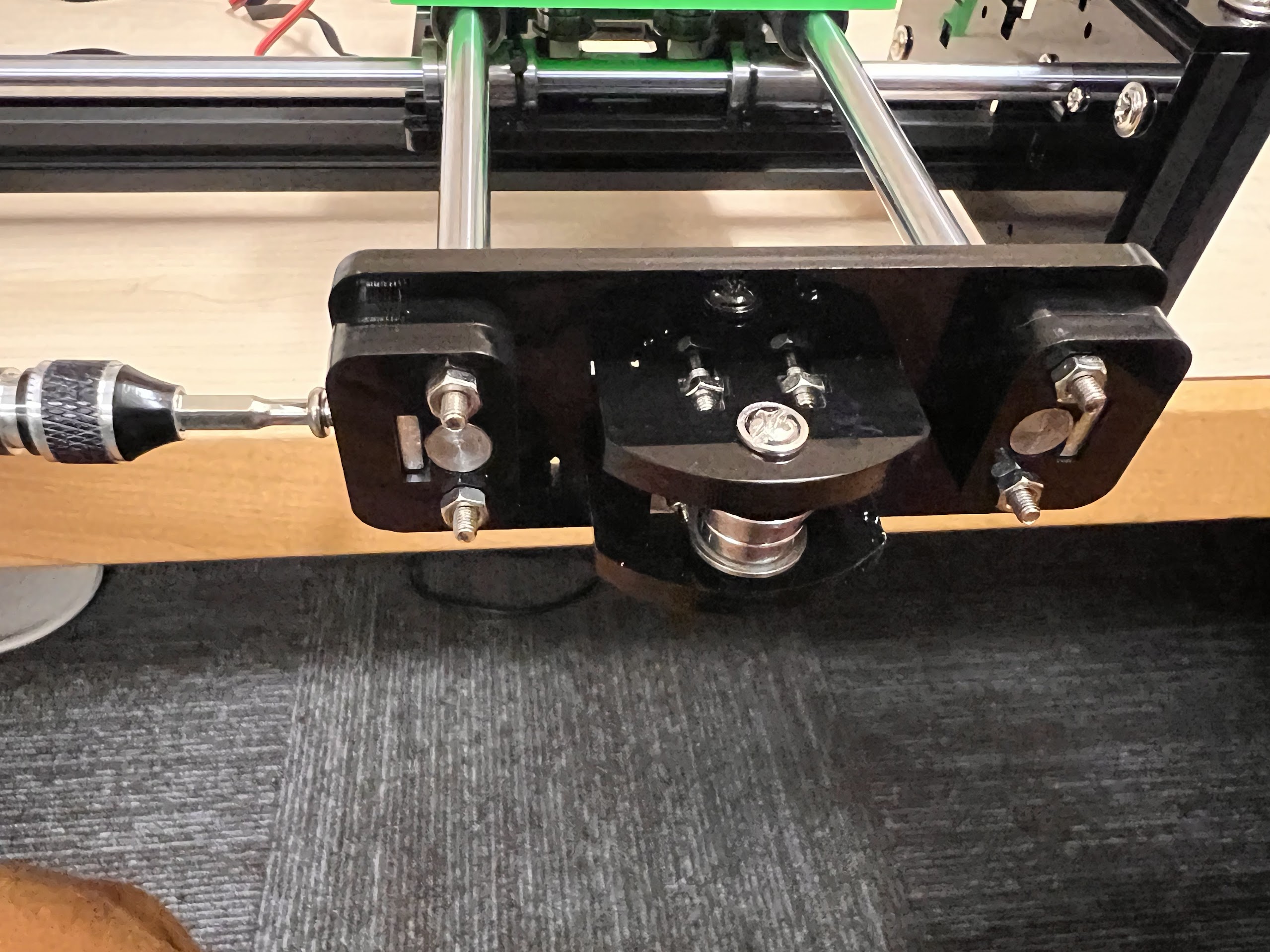
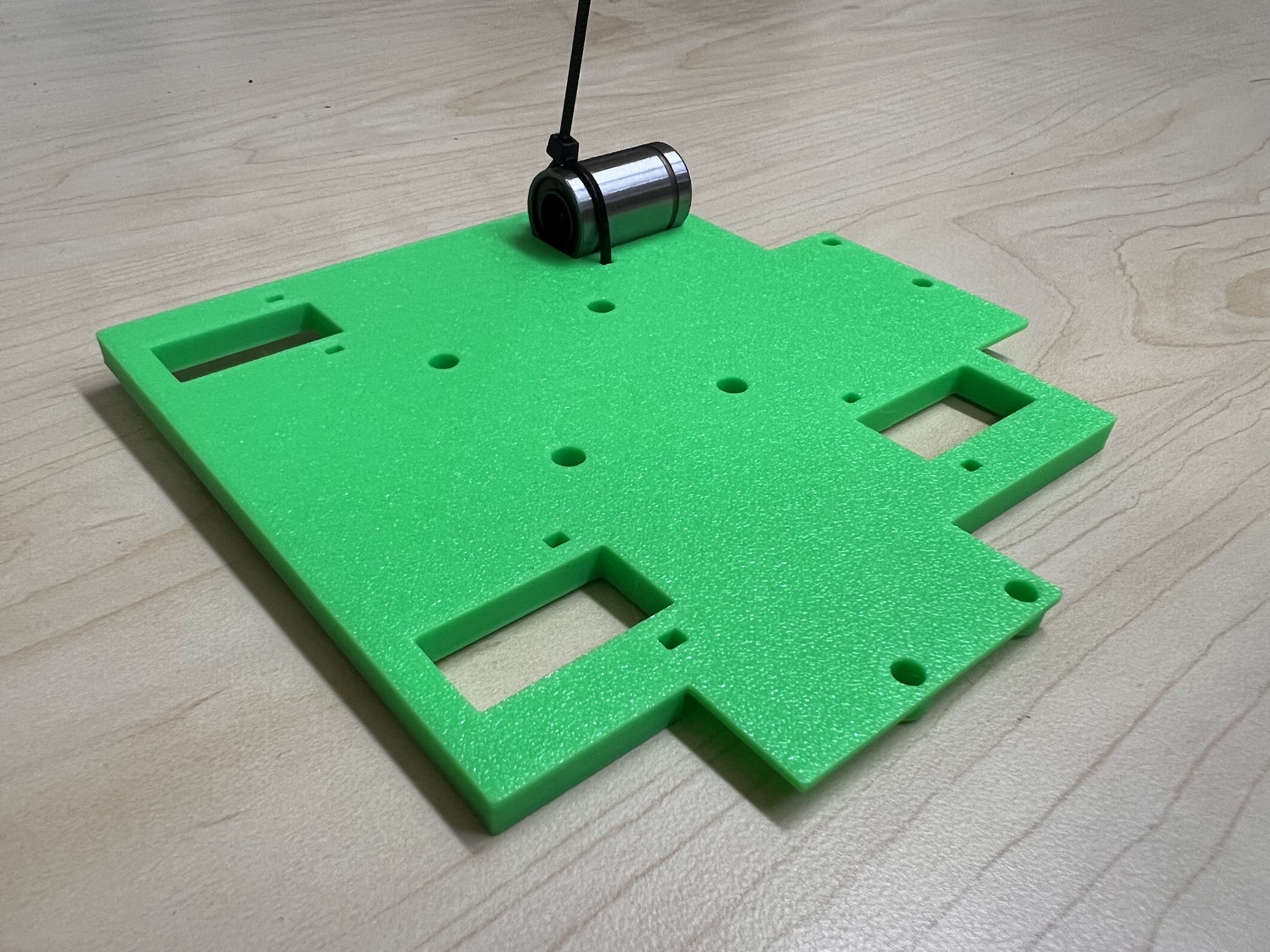
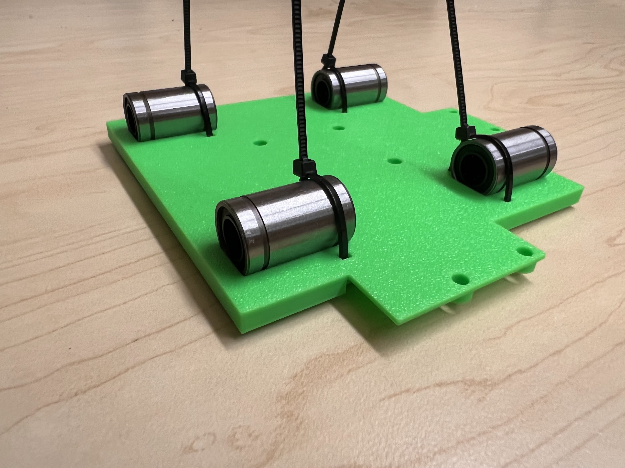
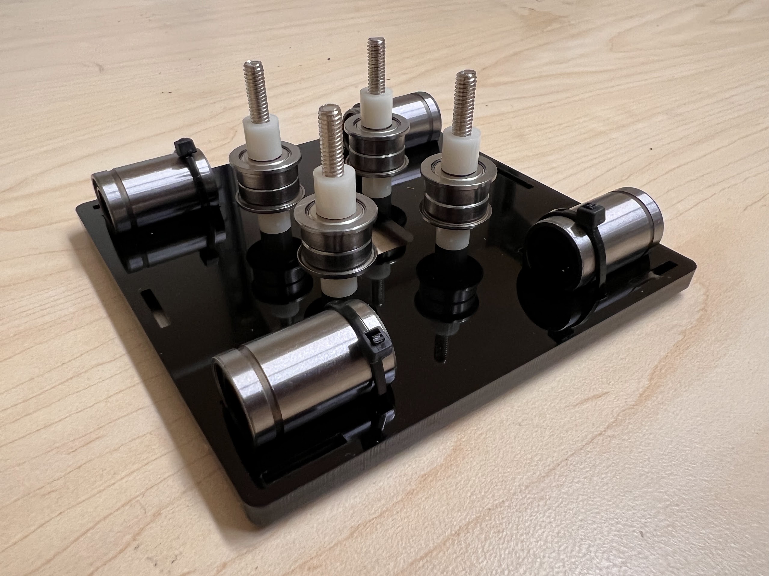
- With all the Linear Bearings attached the Top Cross Slide should look like this.
- Using the Cutters from the 3D Printing Accessories Kit, cut the ends of the Zip-Ties.
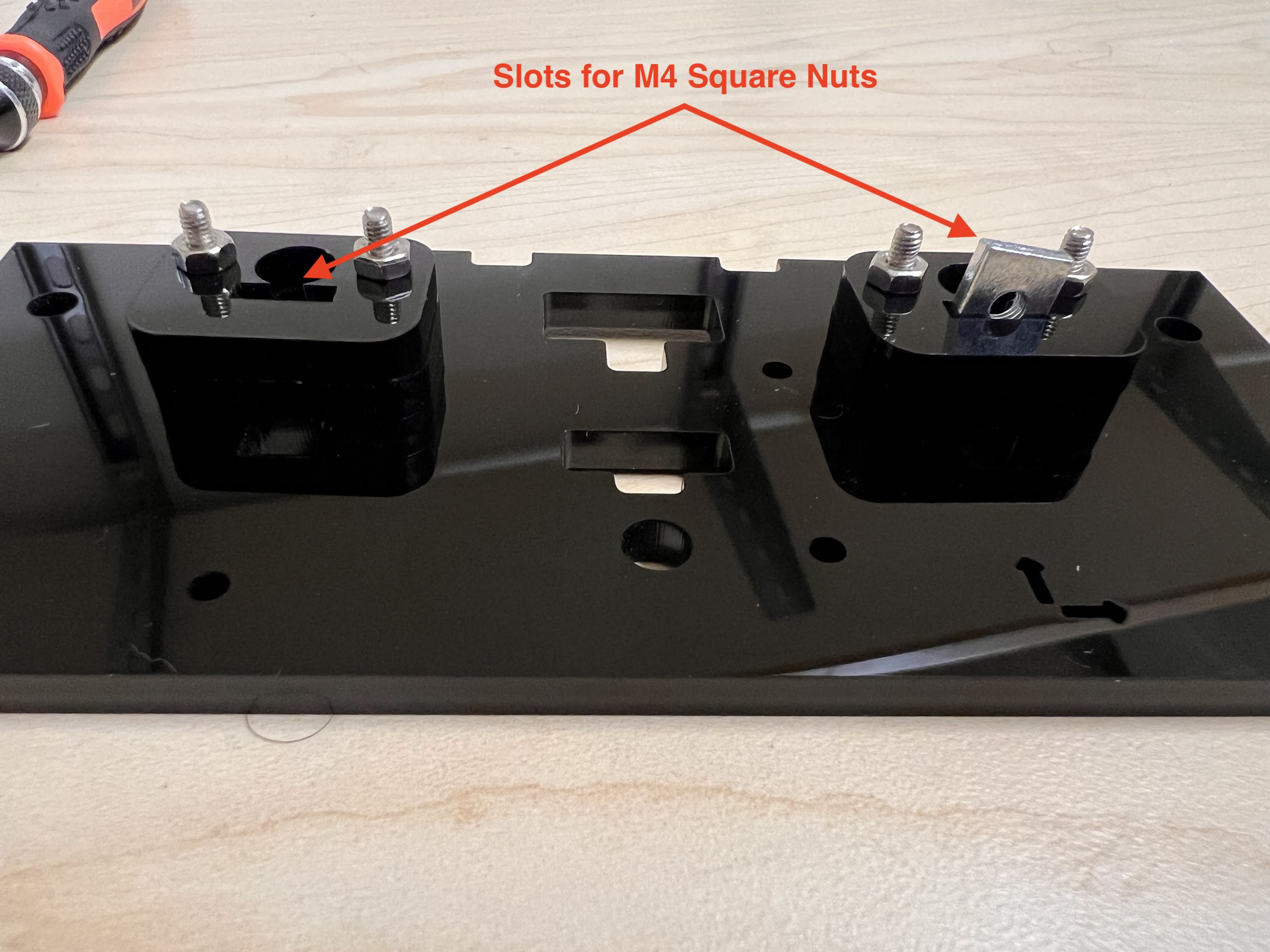
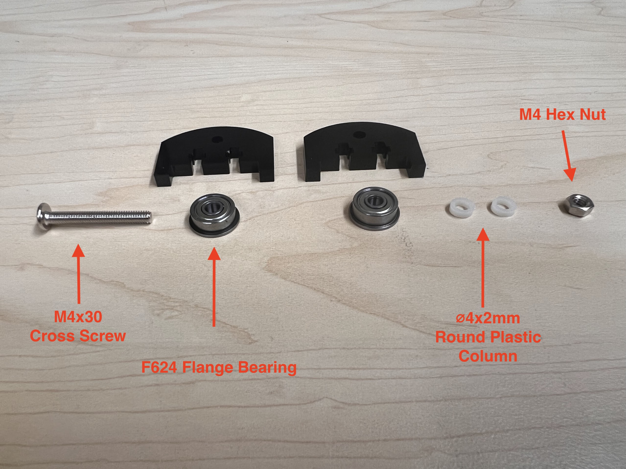
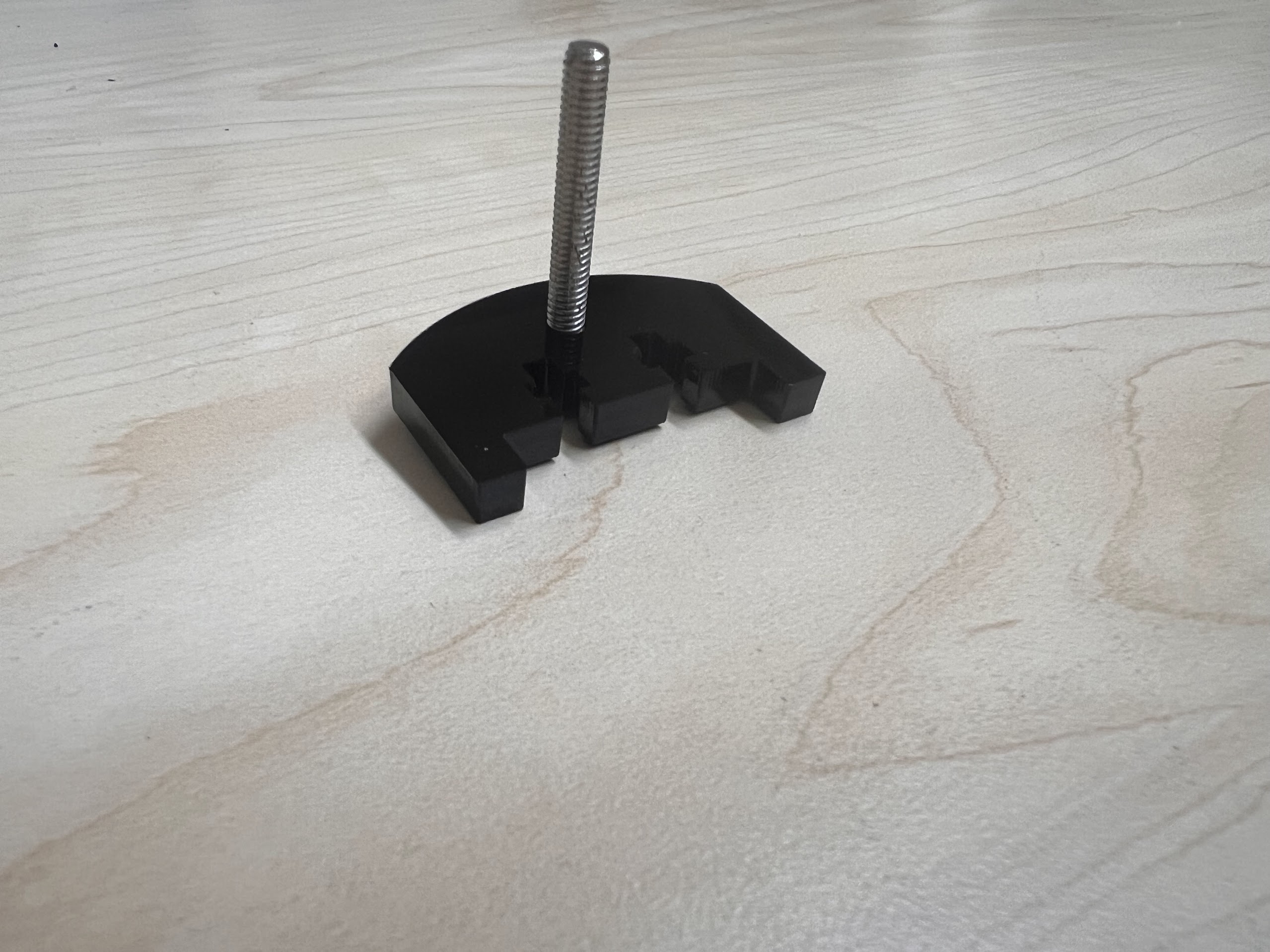
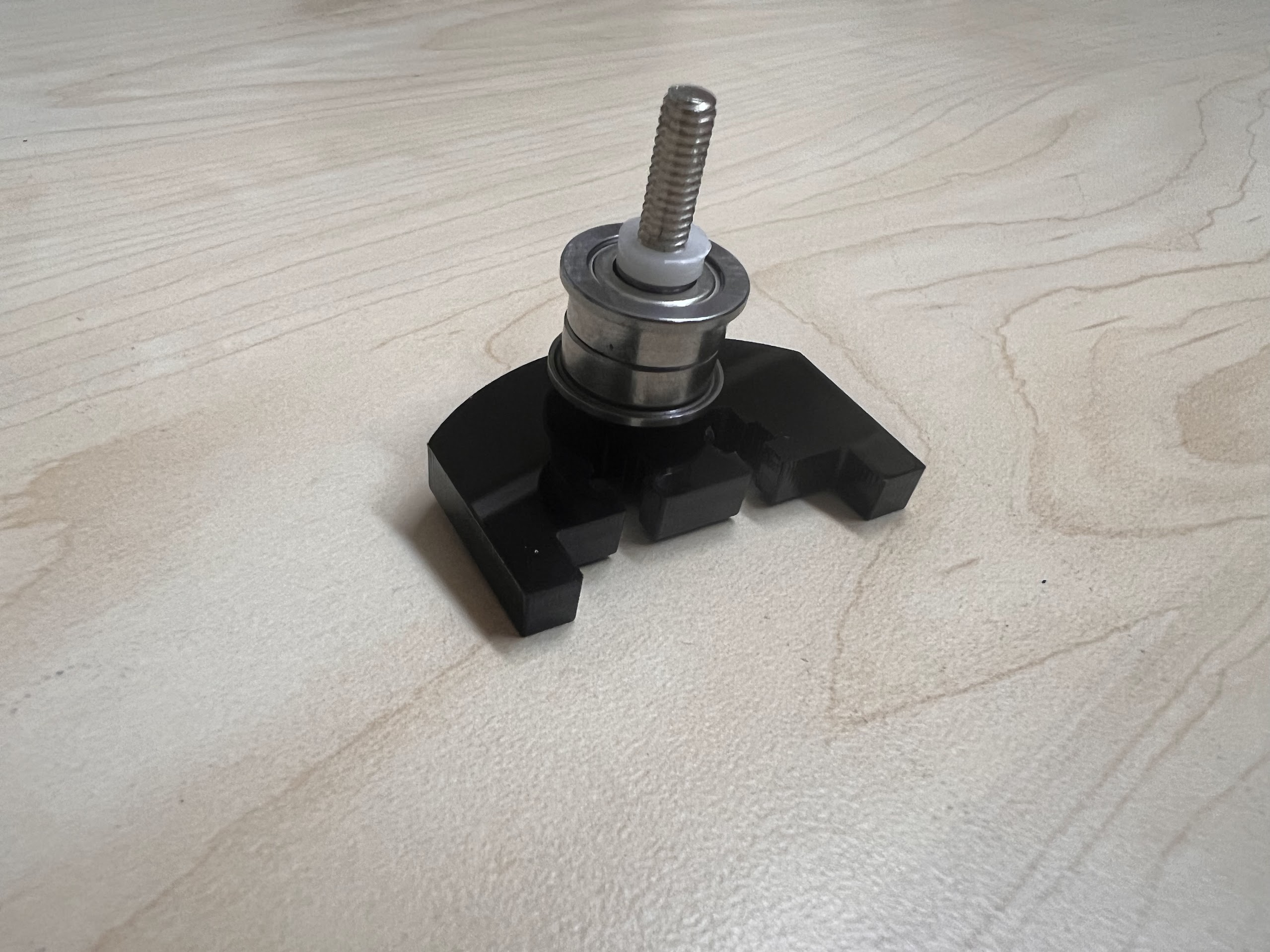
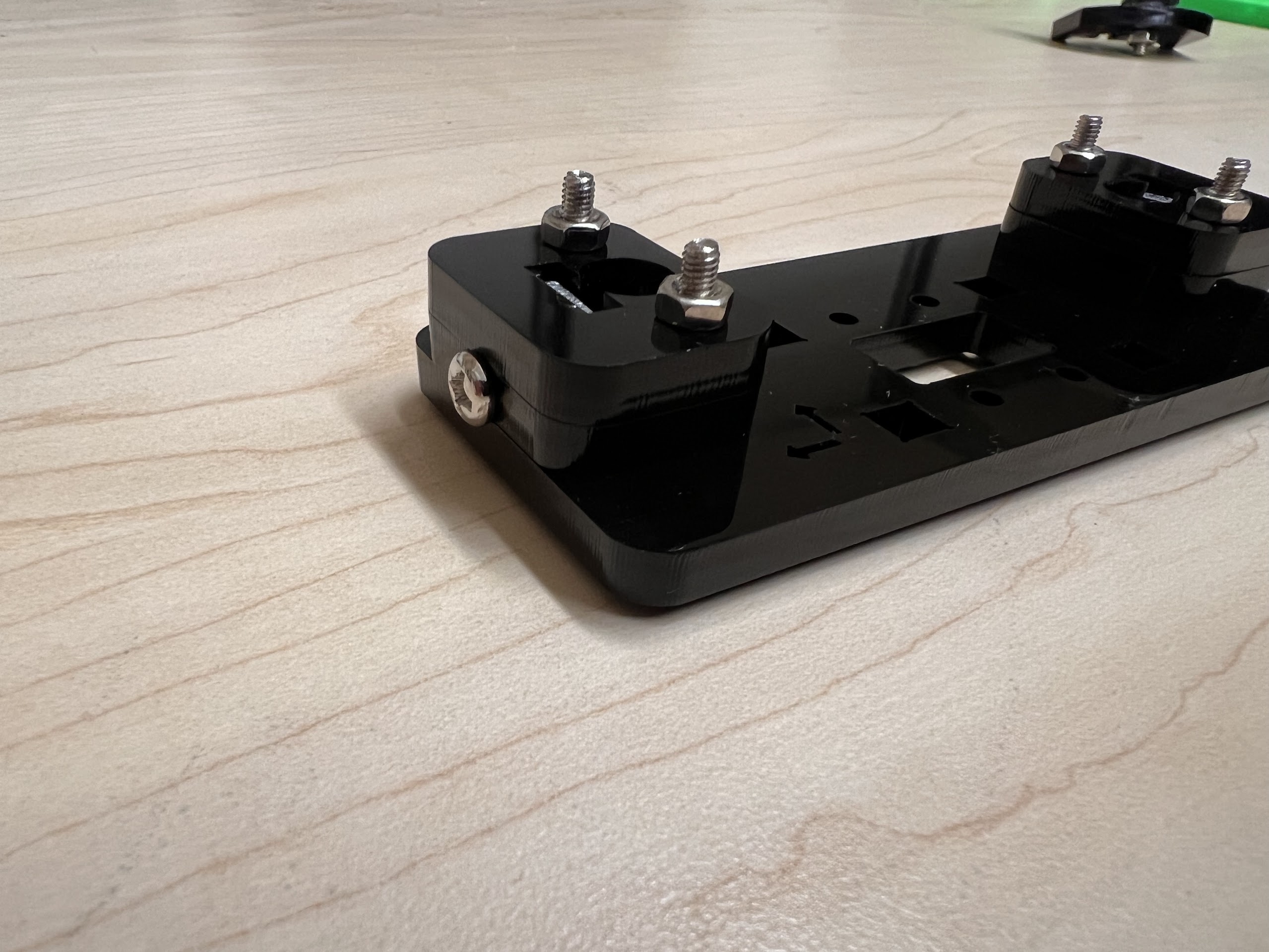
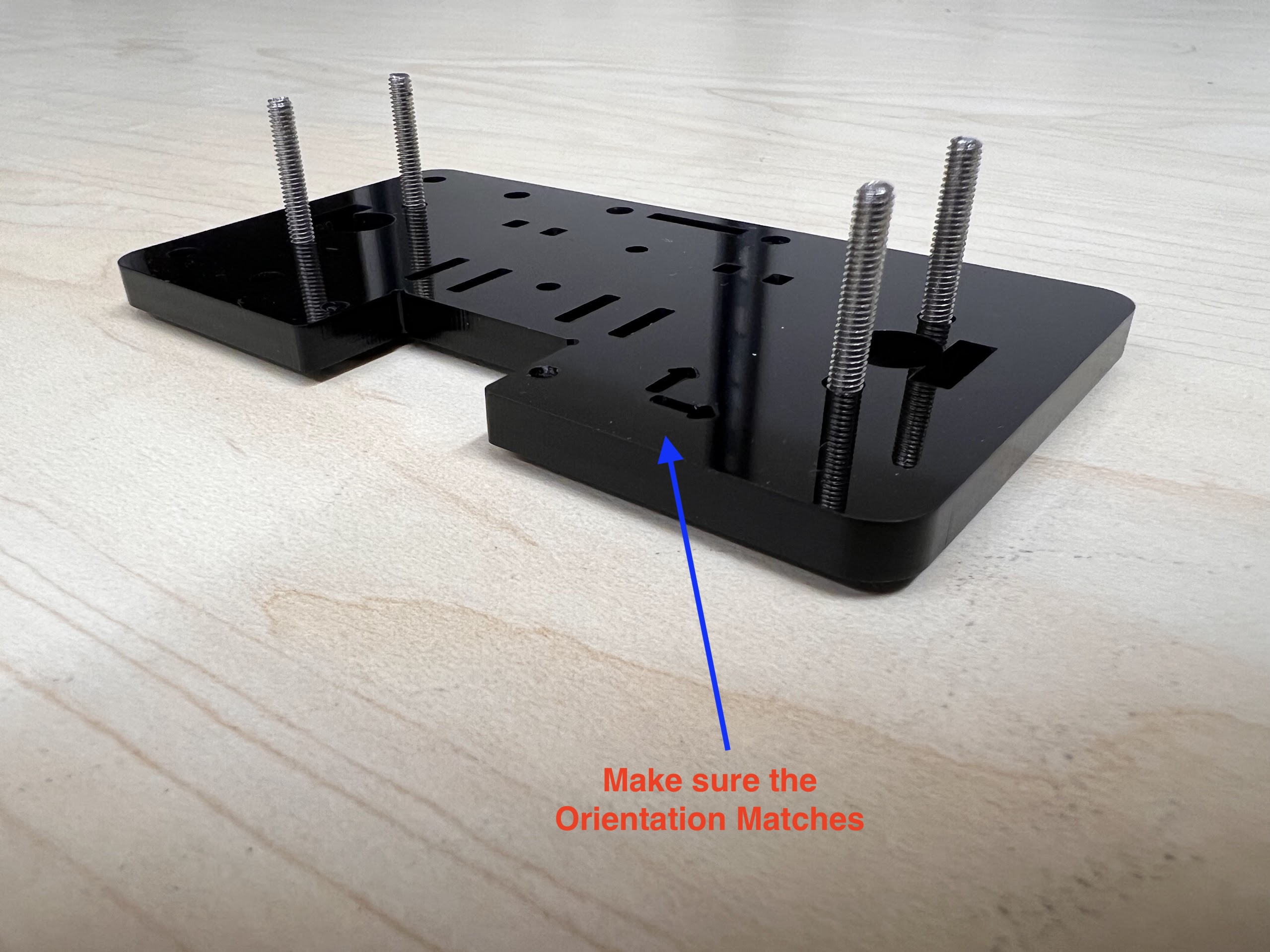
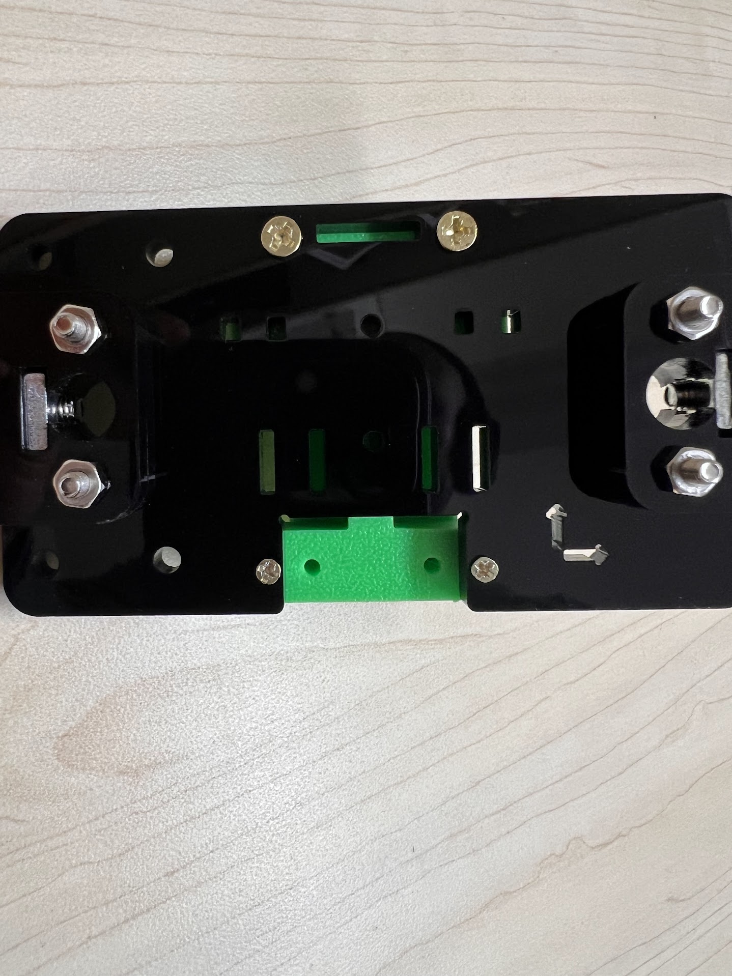
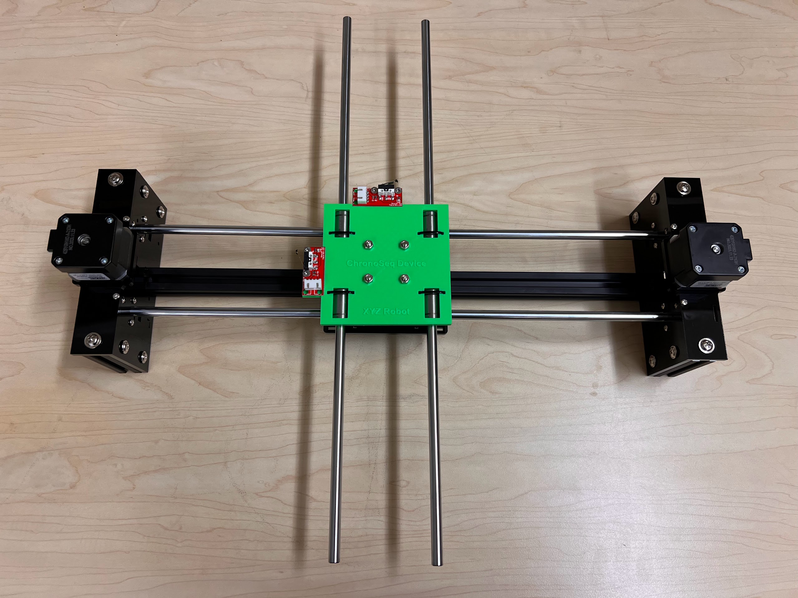
- Push the M4x40mm Cross Screws through the Bottom Cross Slide.
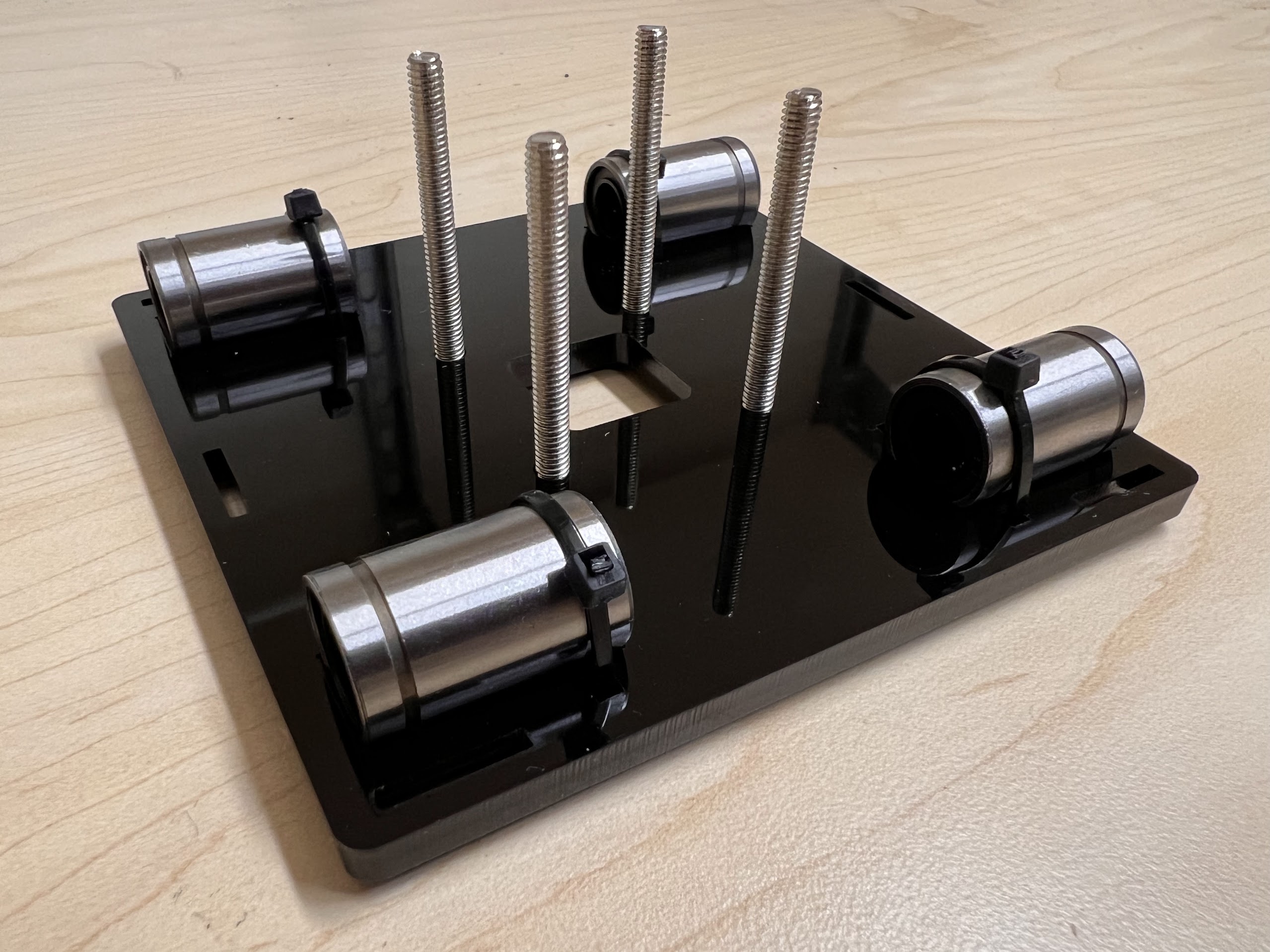
- Place four ⌀4x7mm Round Plastic Column pieces on Top.
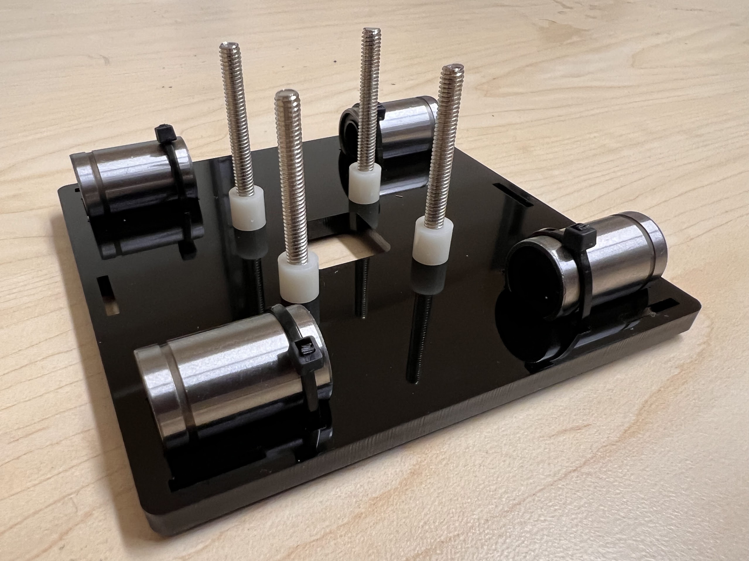
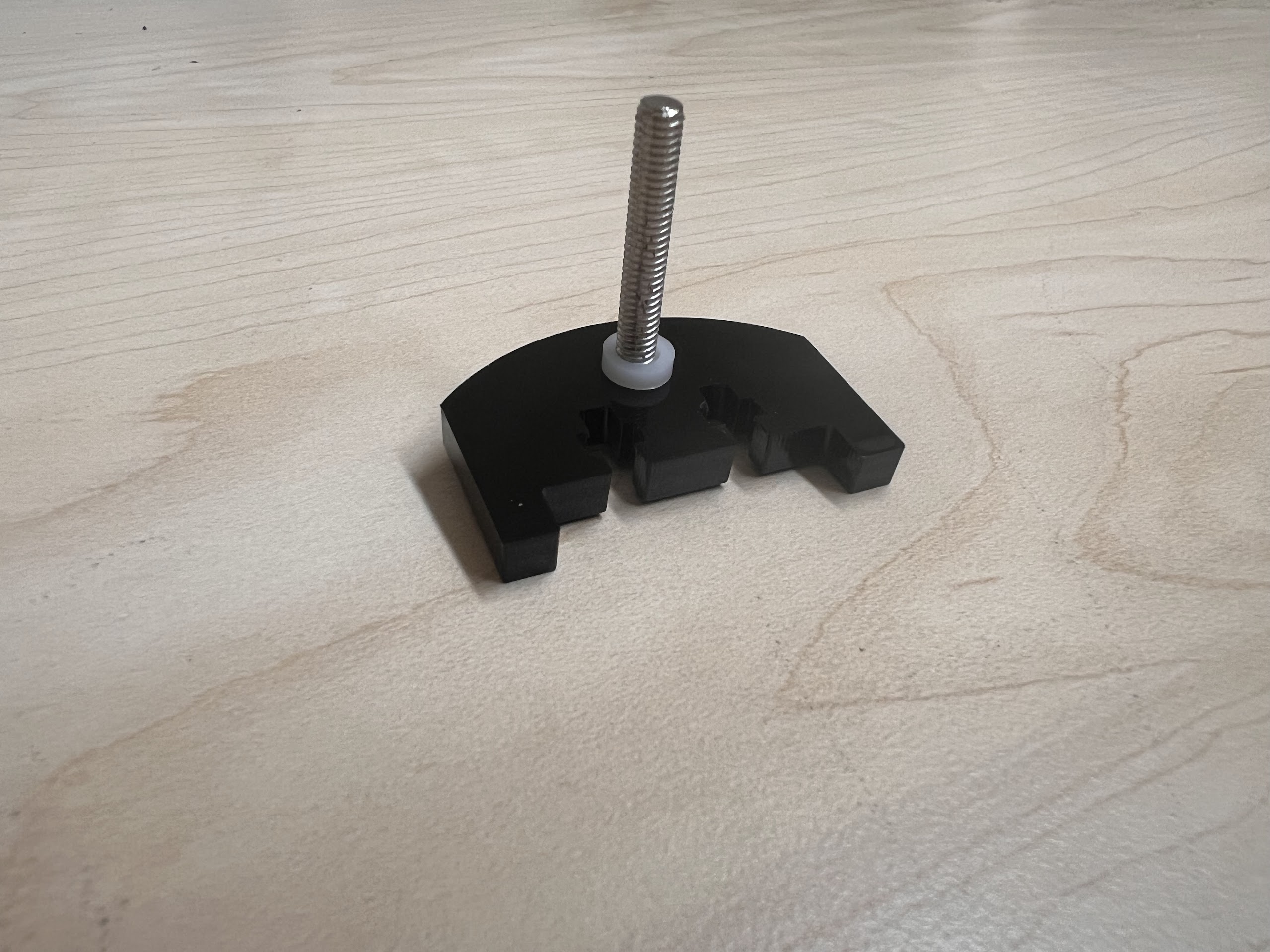
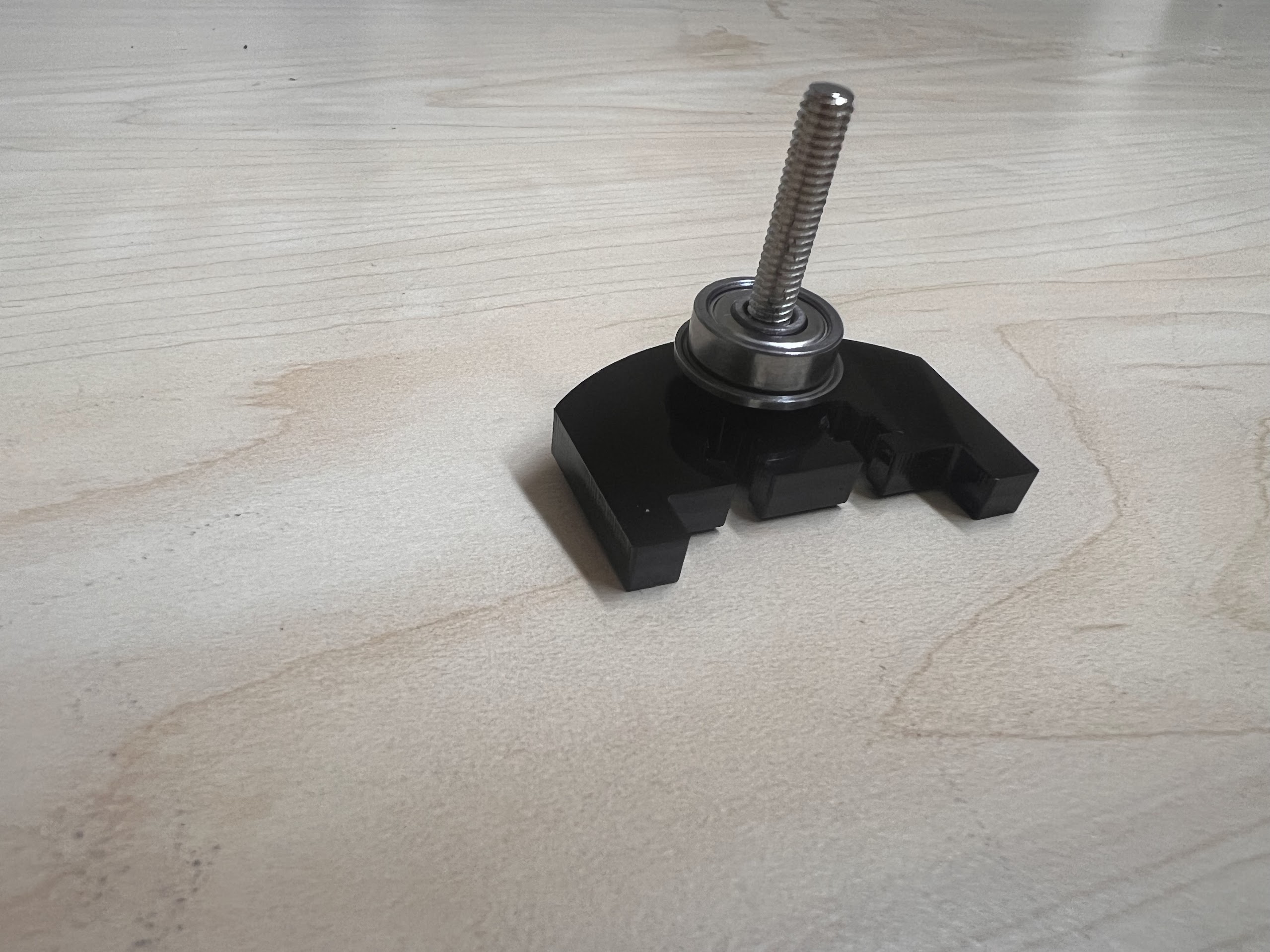
- Place four F624 Flange Bearings on top with the Flange facing downwards. The Flange is the wider part of the Bearing.
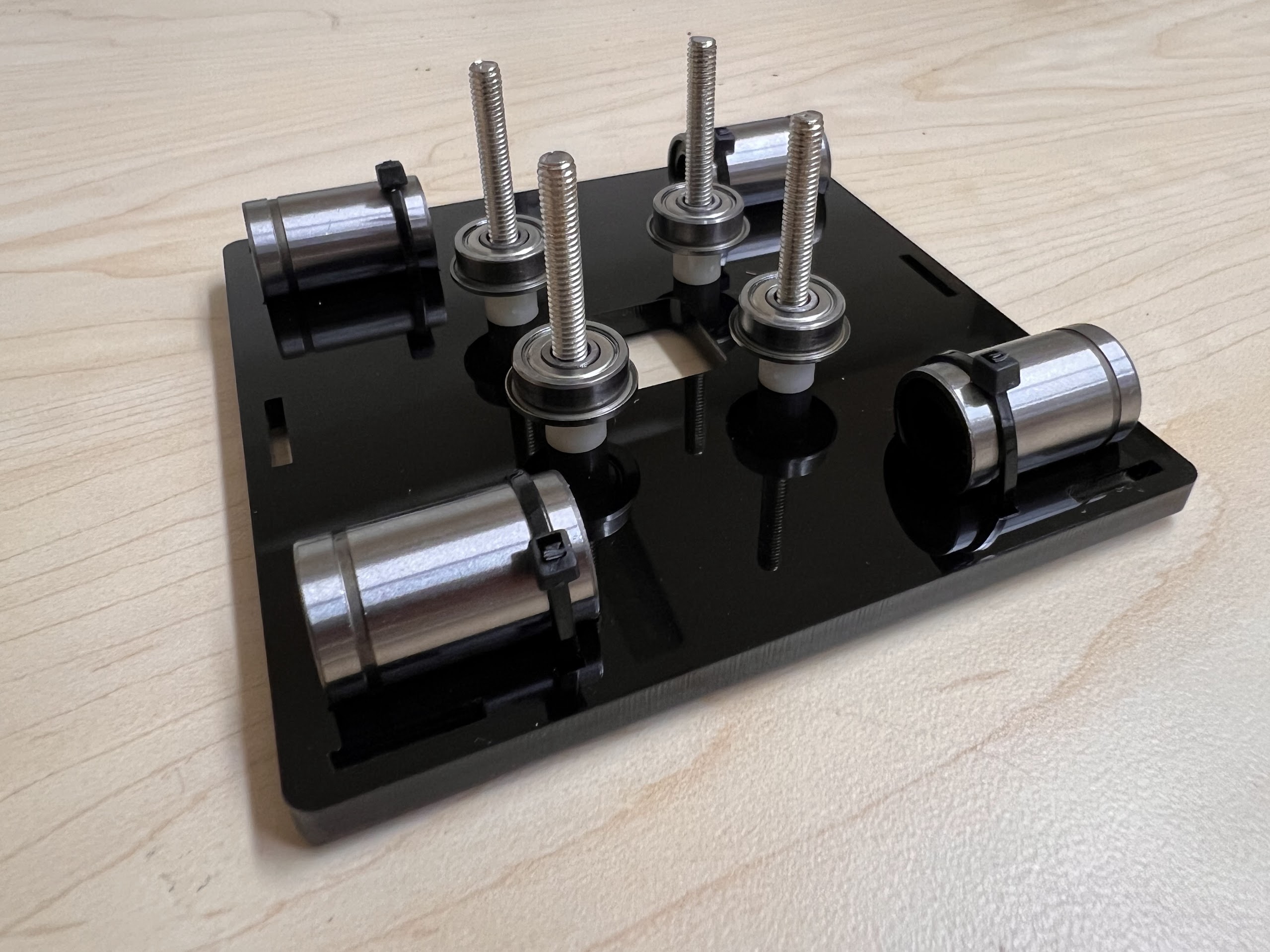
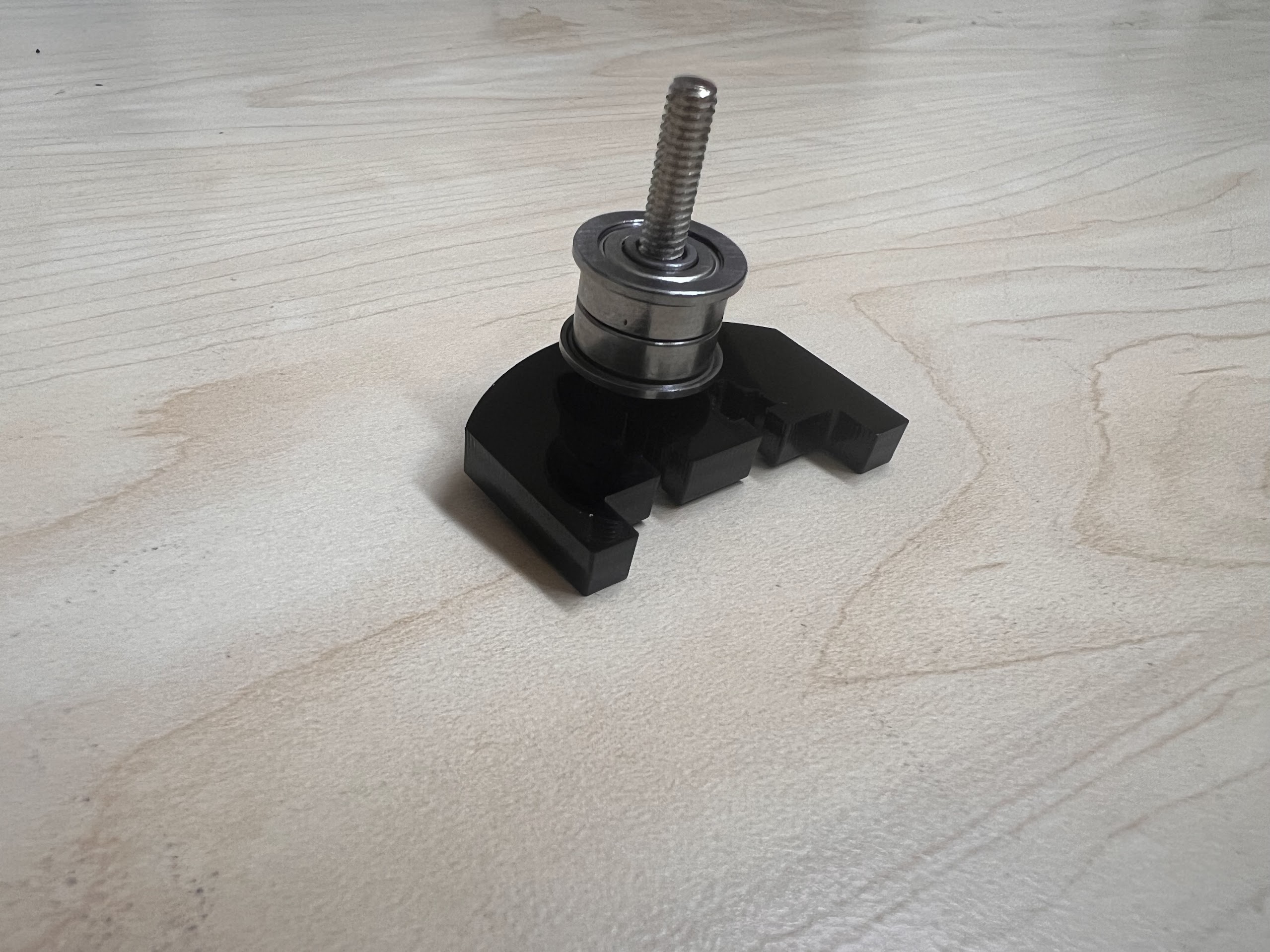
- Place another four F624 Flange Bearings on top with the Flange facing upwards.
- Place another four ⌀4x7mm Round Plastic Column pieces on Top.
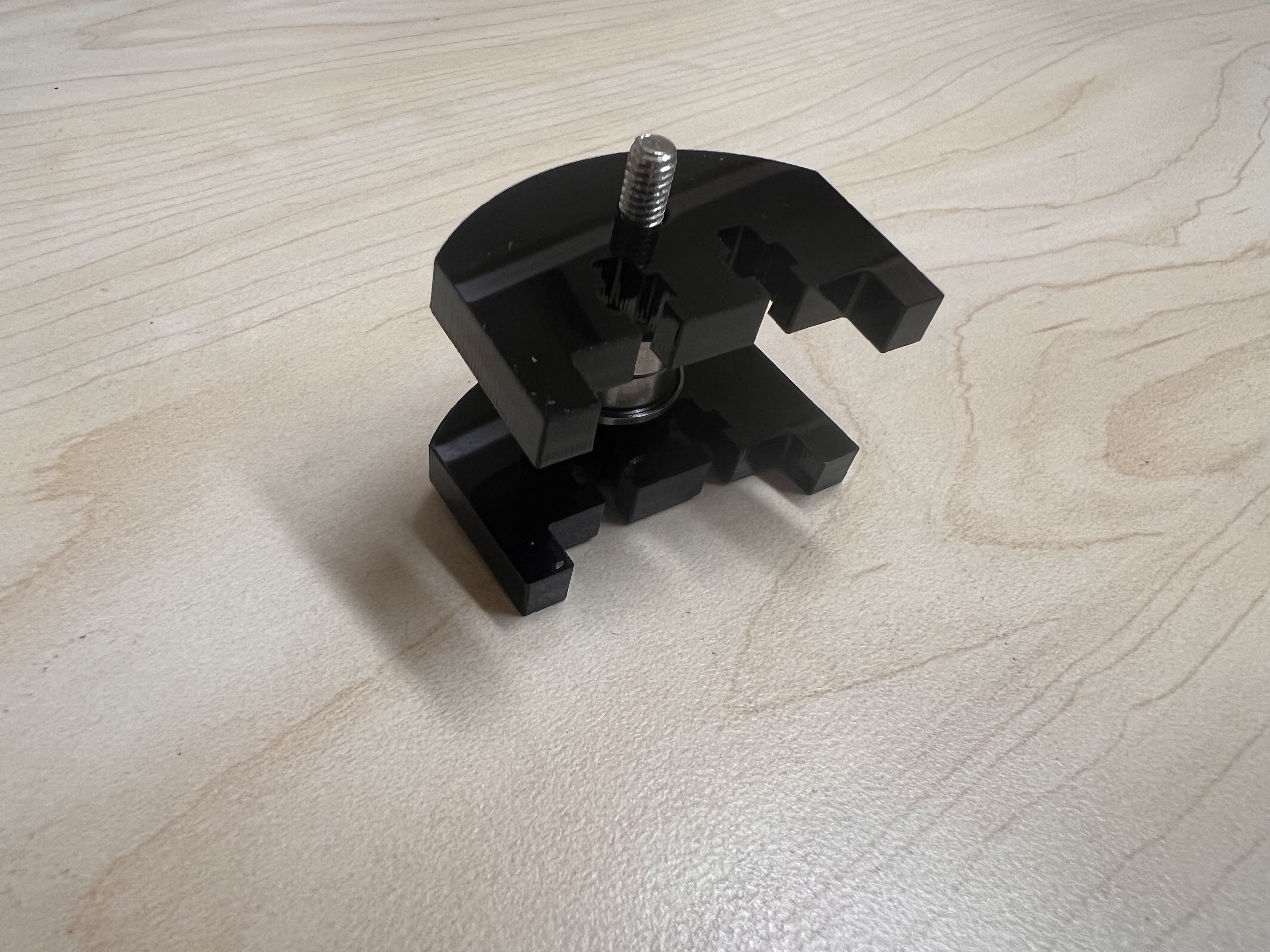
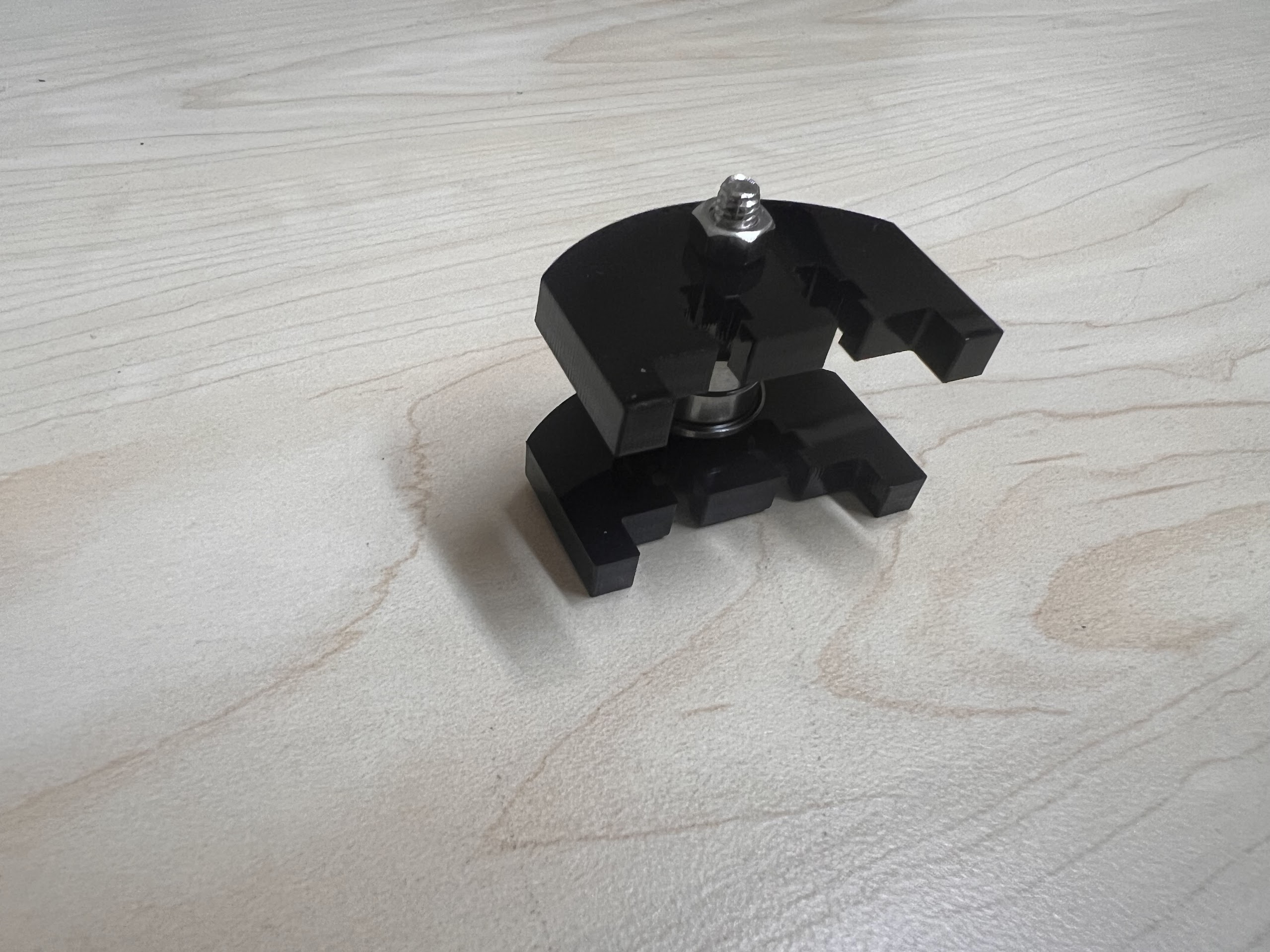
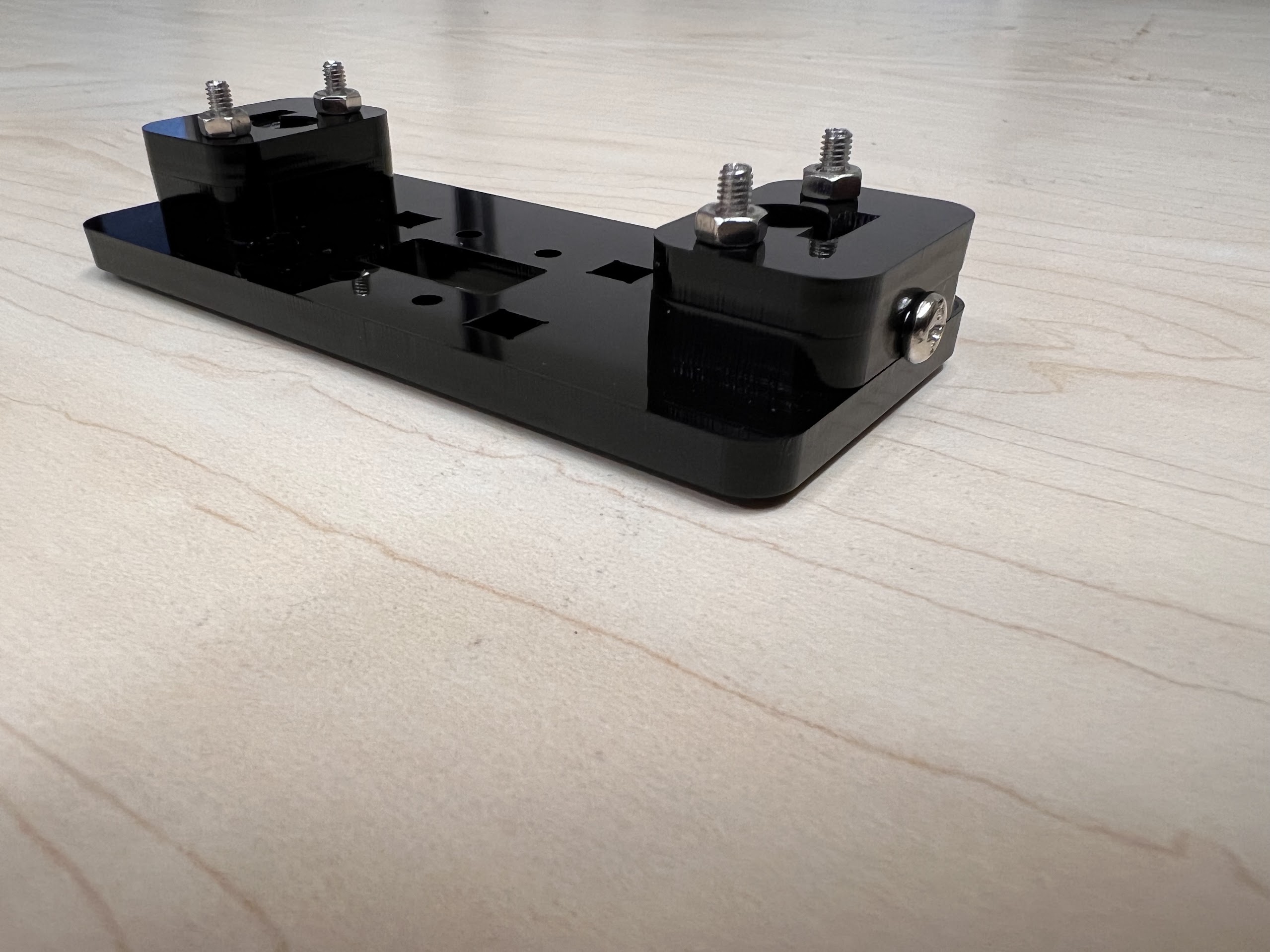
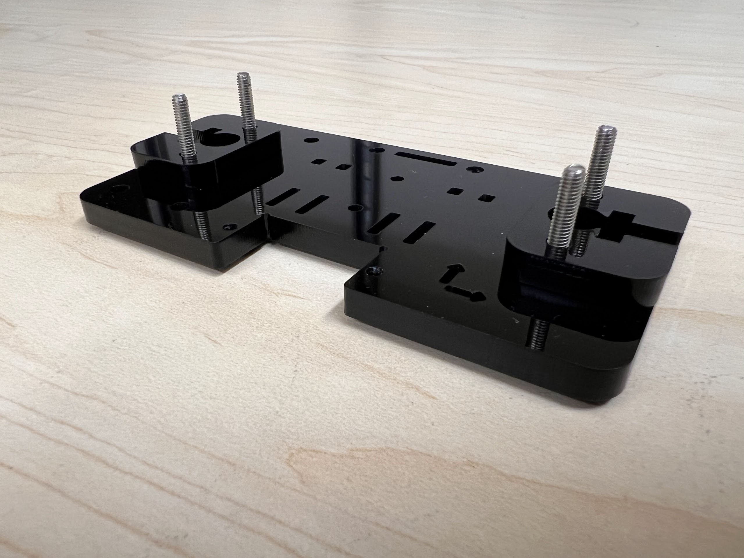
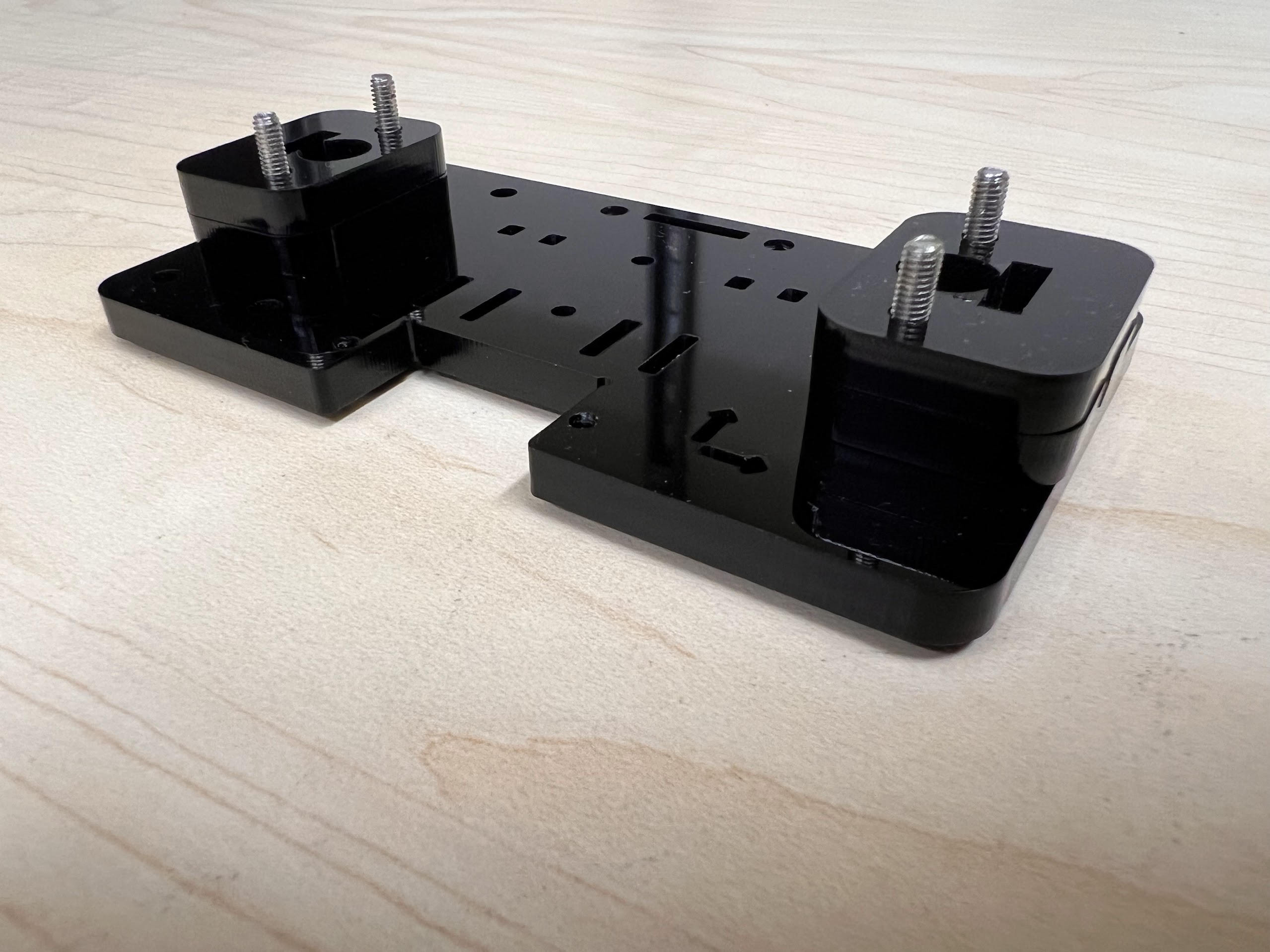
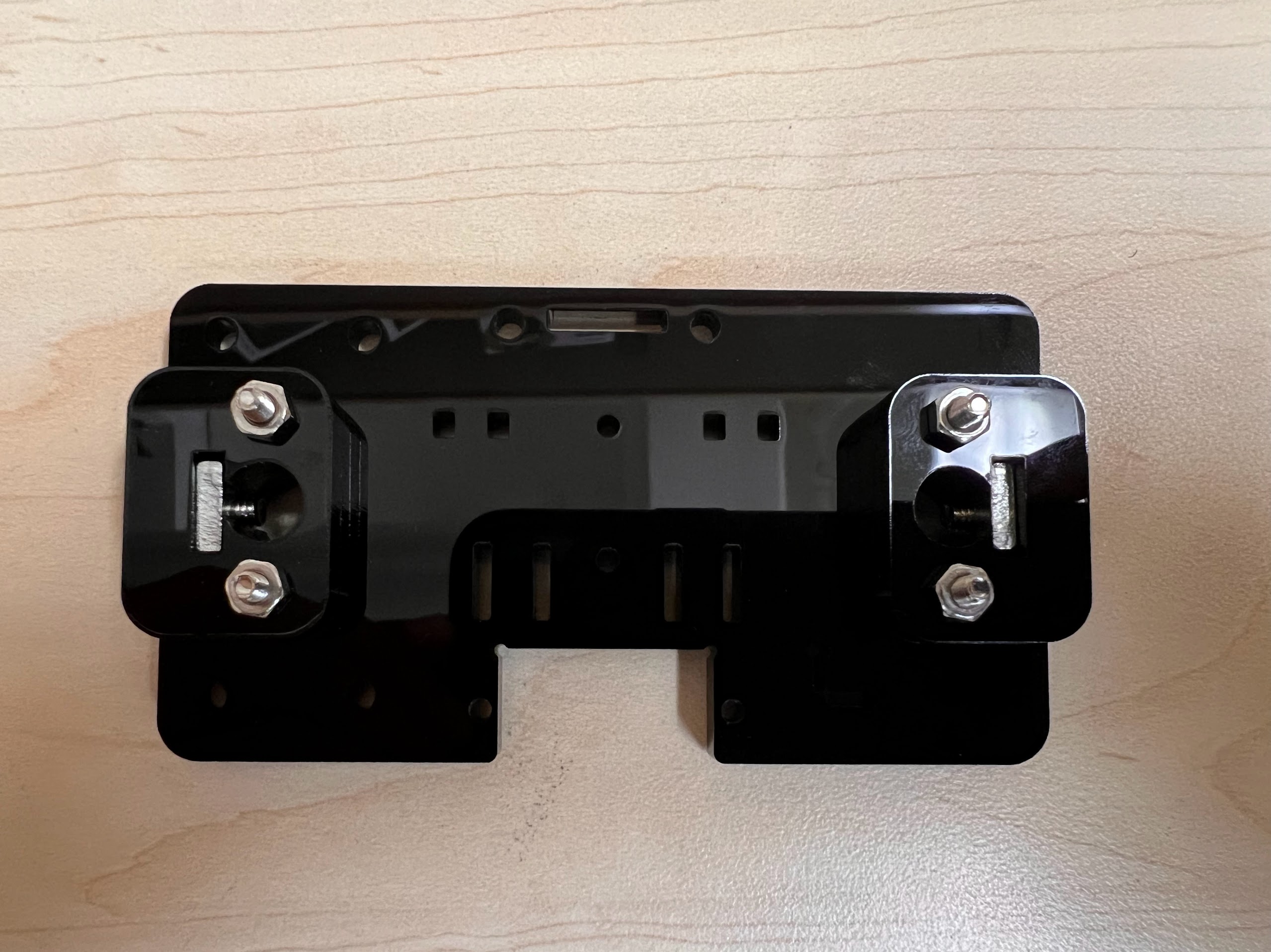
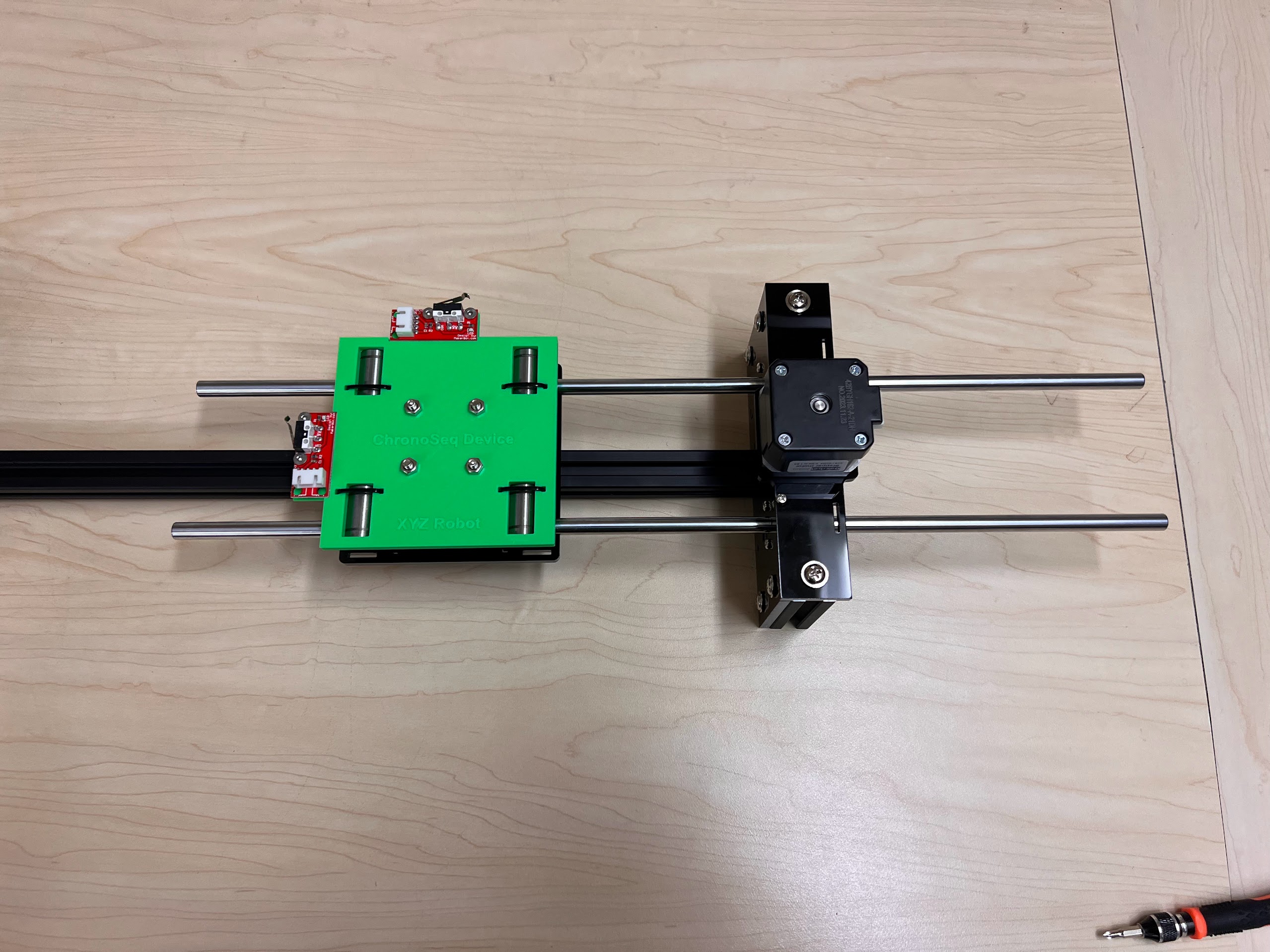
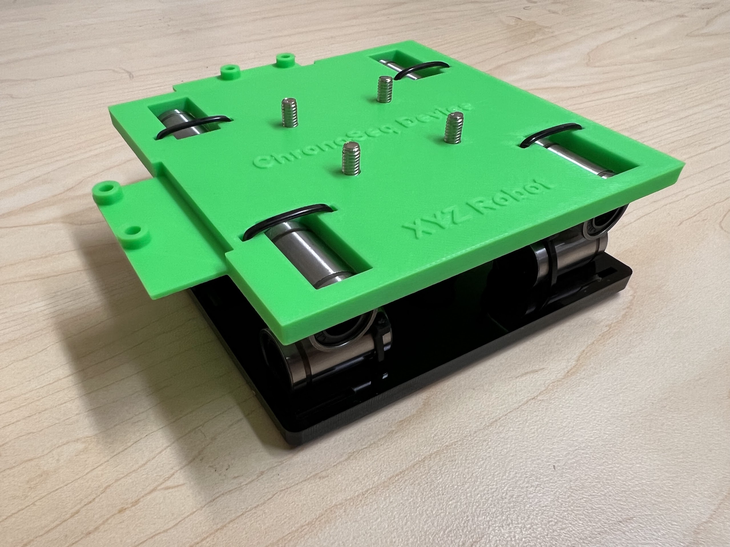
- Now Place the Assembled 3D Printed Top Cross Slide on Top. The Text should be visible and facing upwards in the orientation shown.
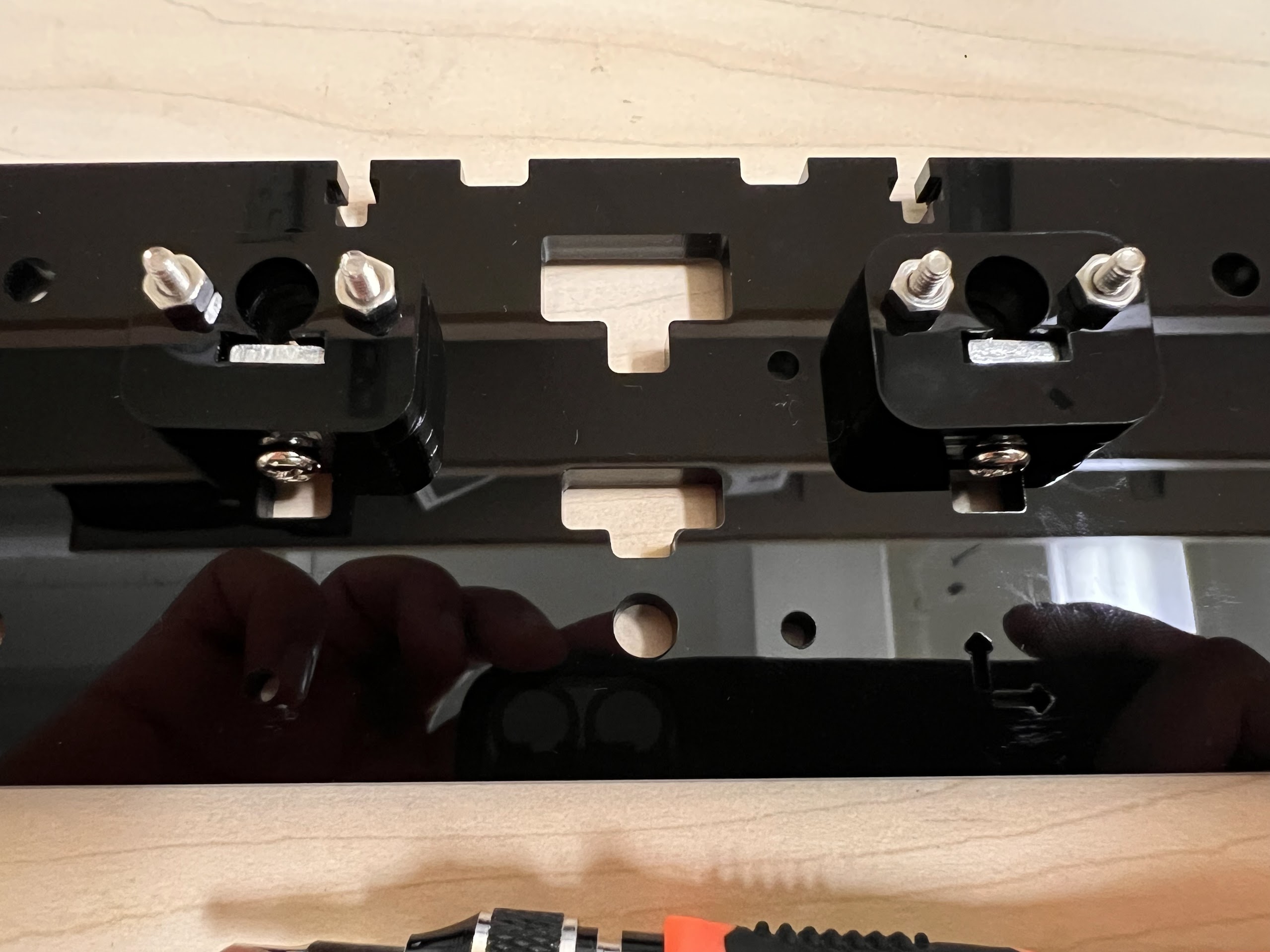
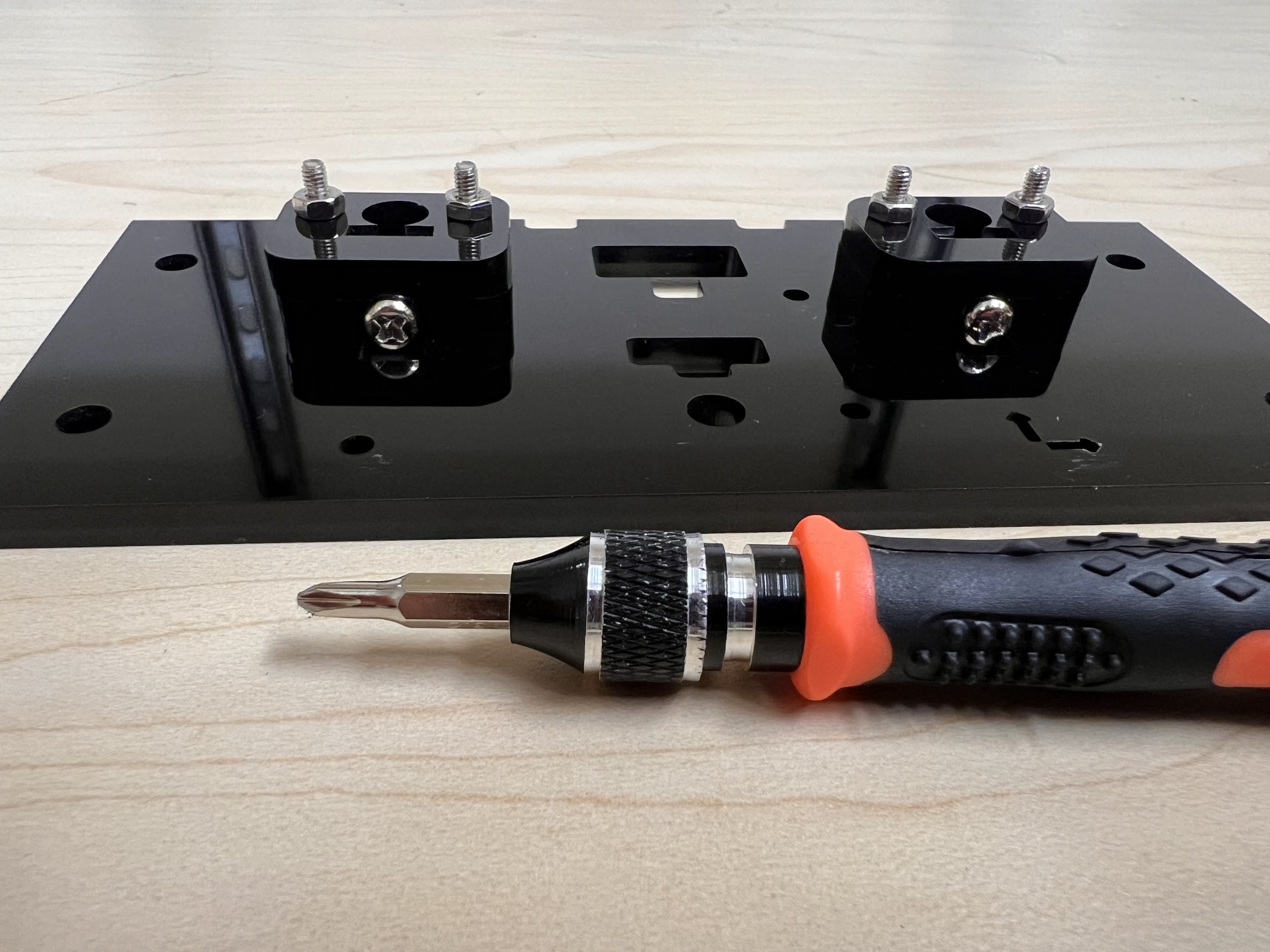
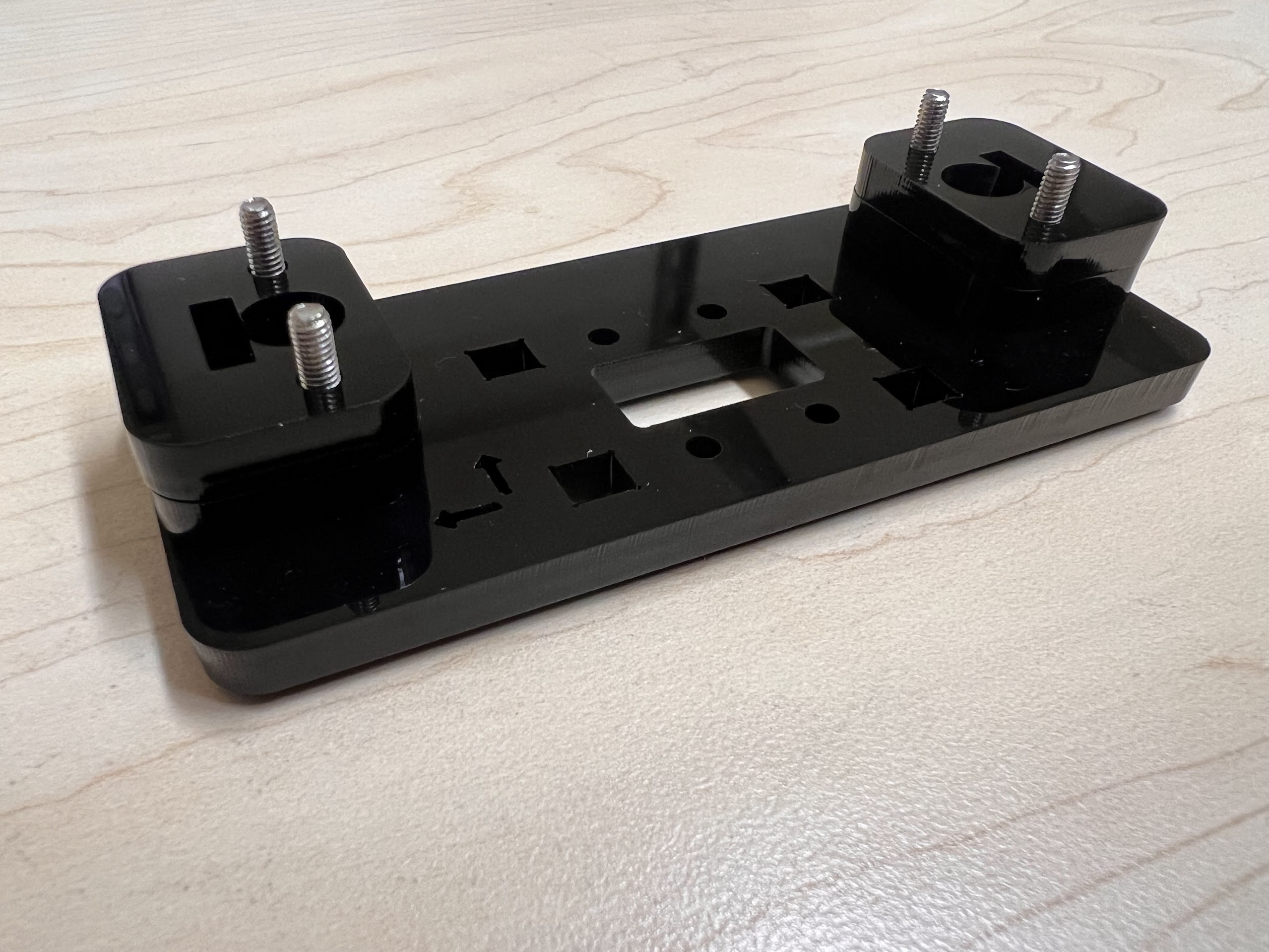
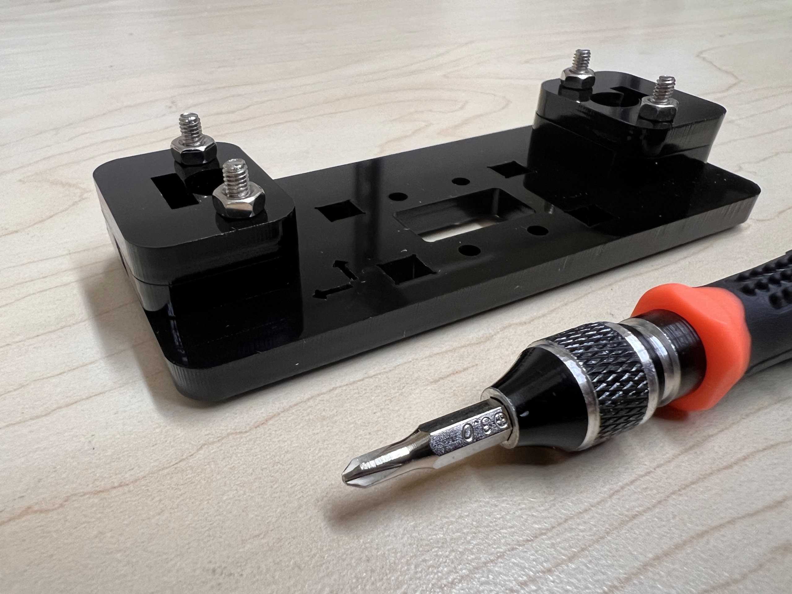
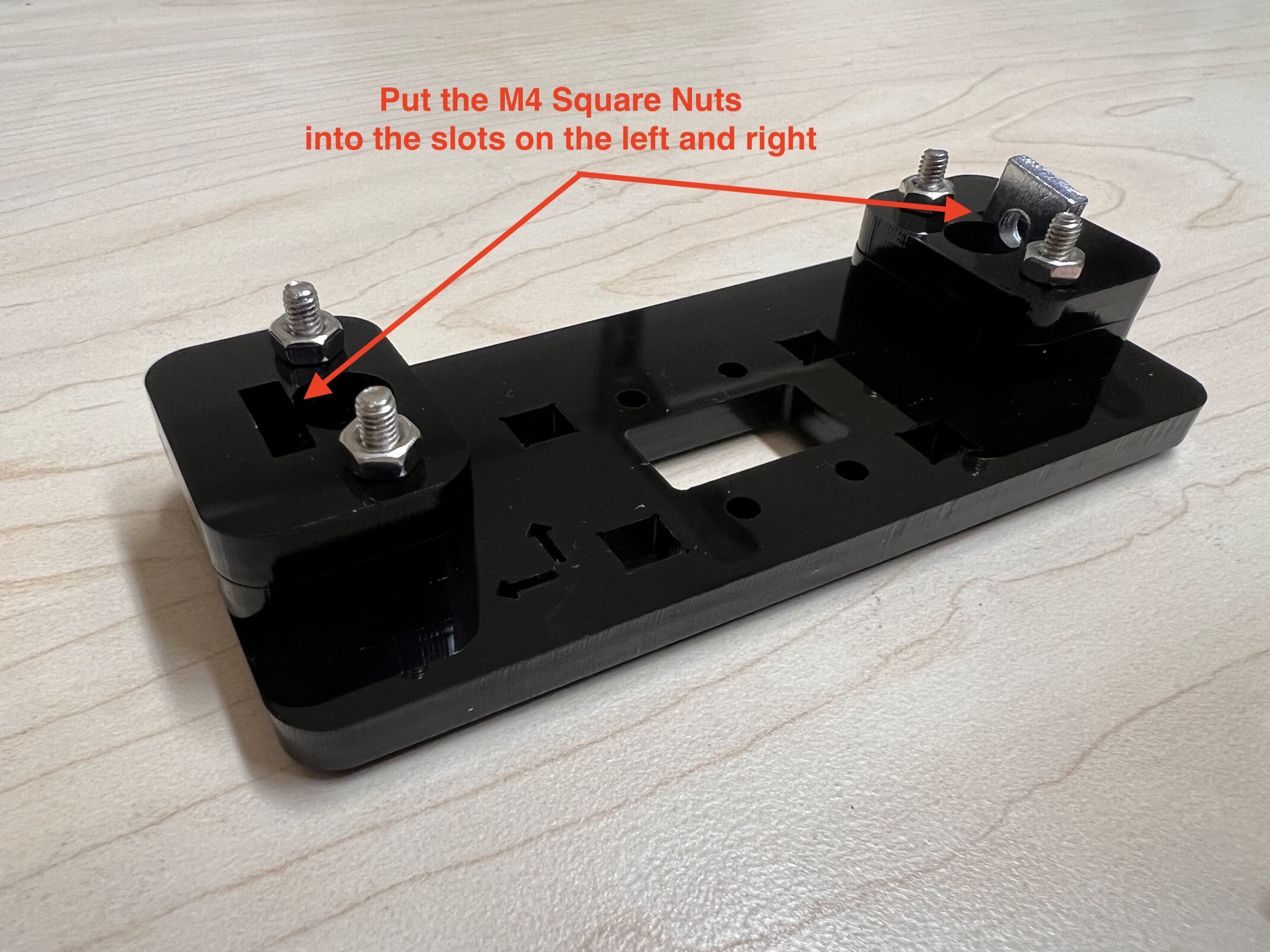
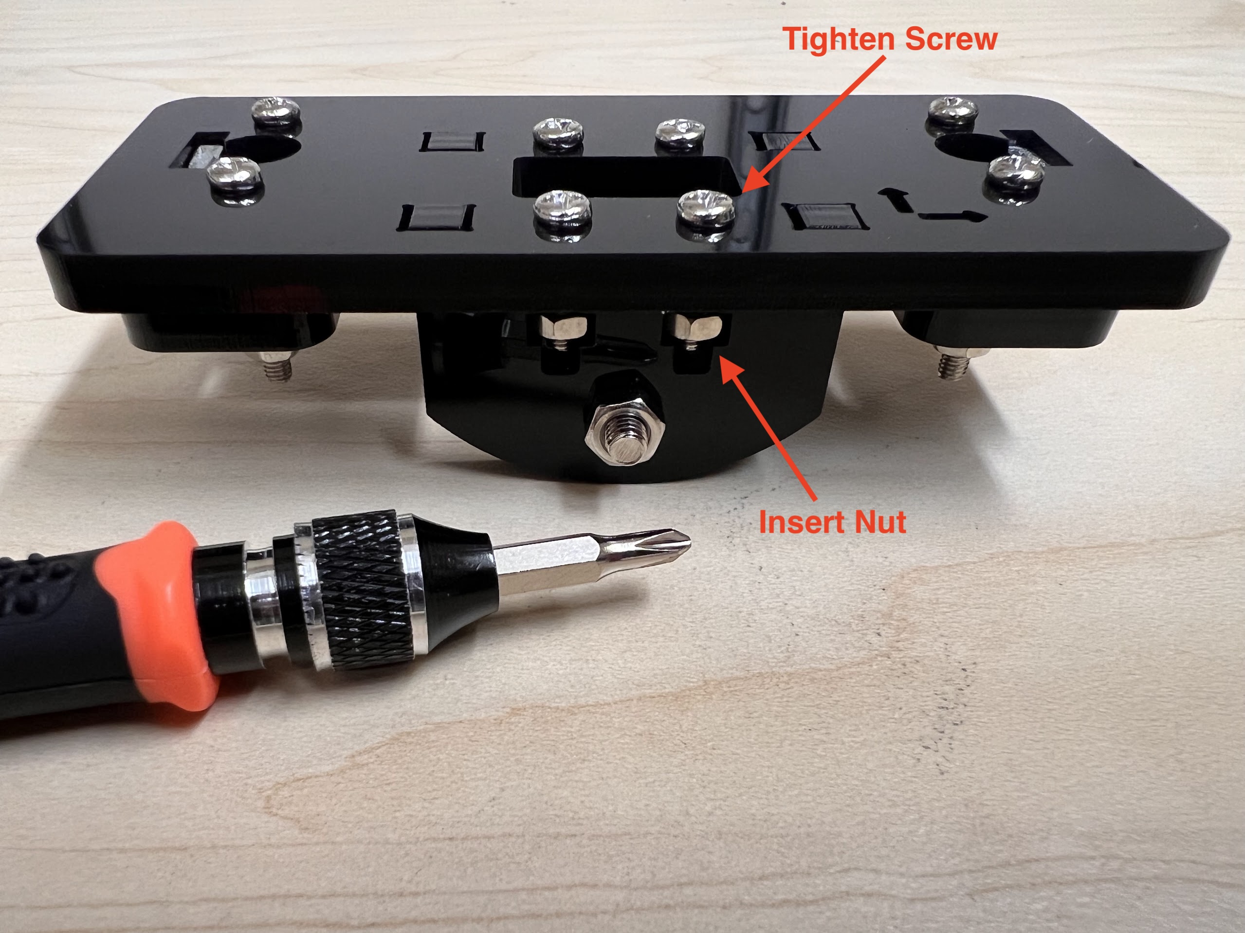
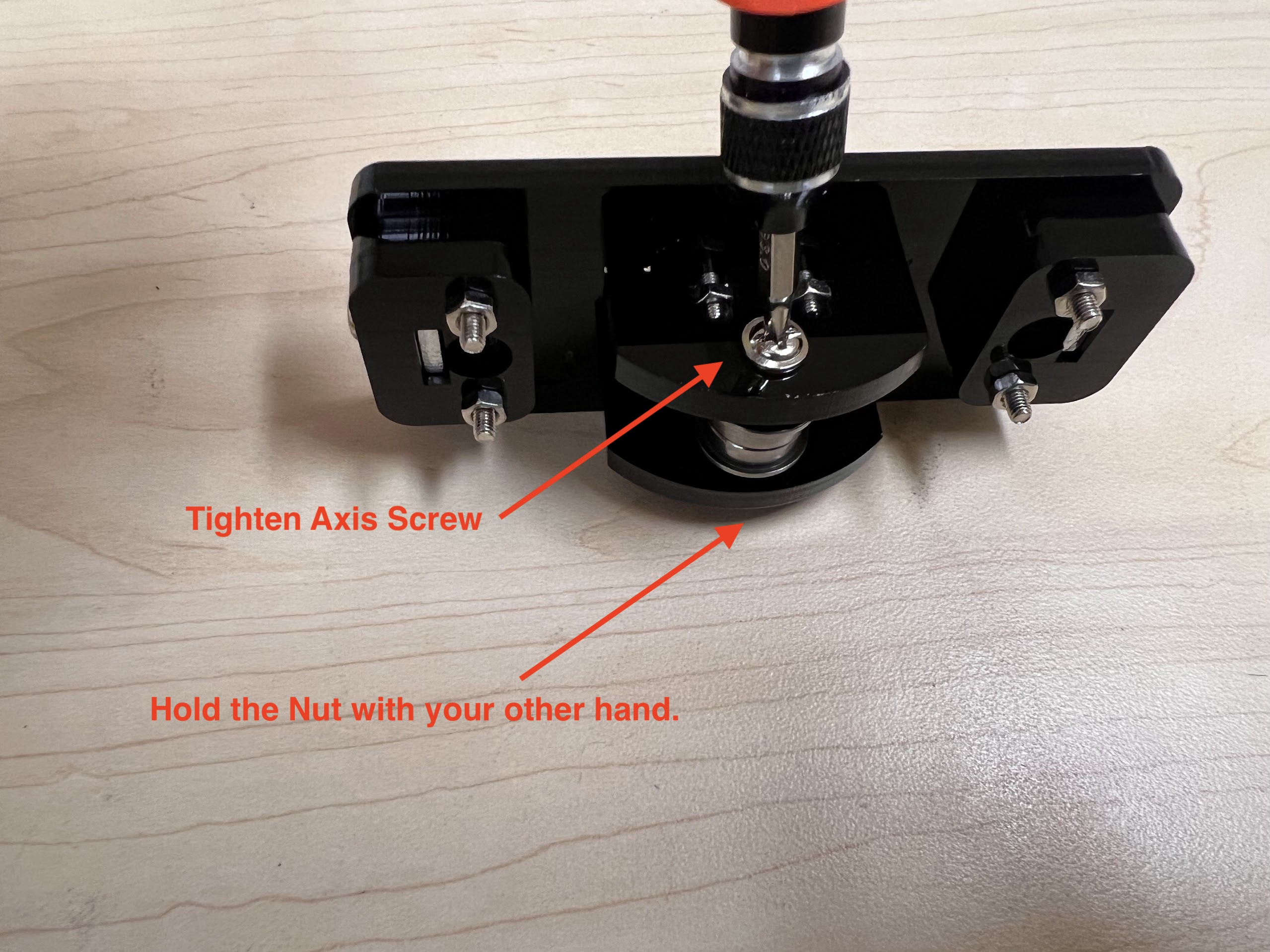
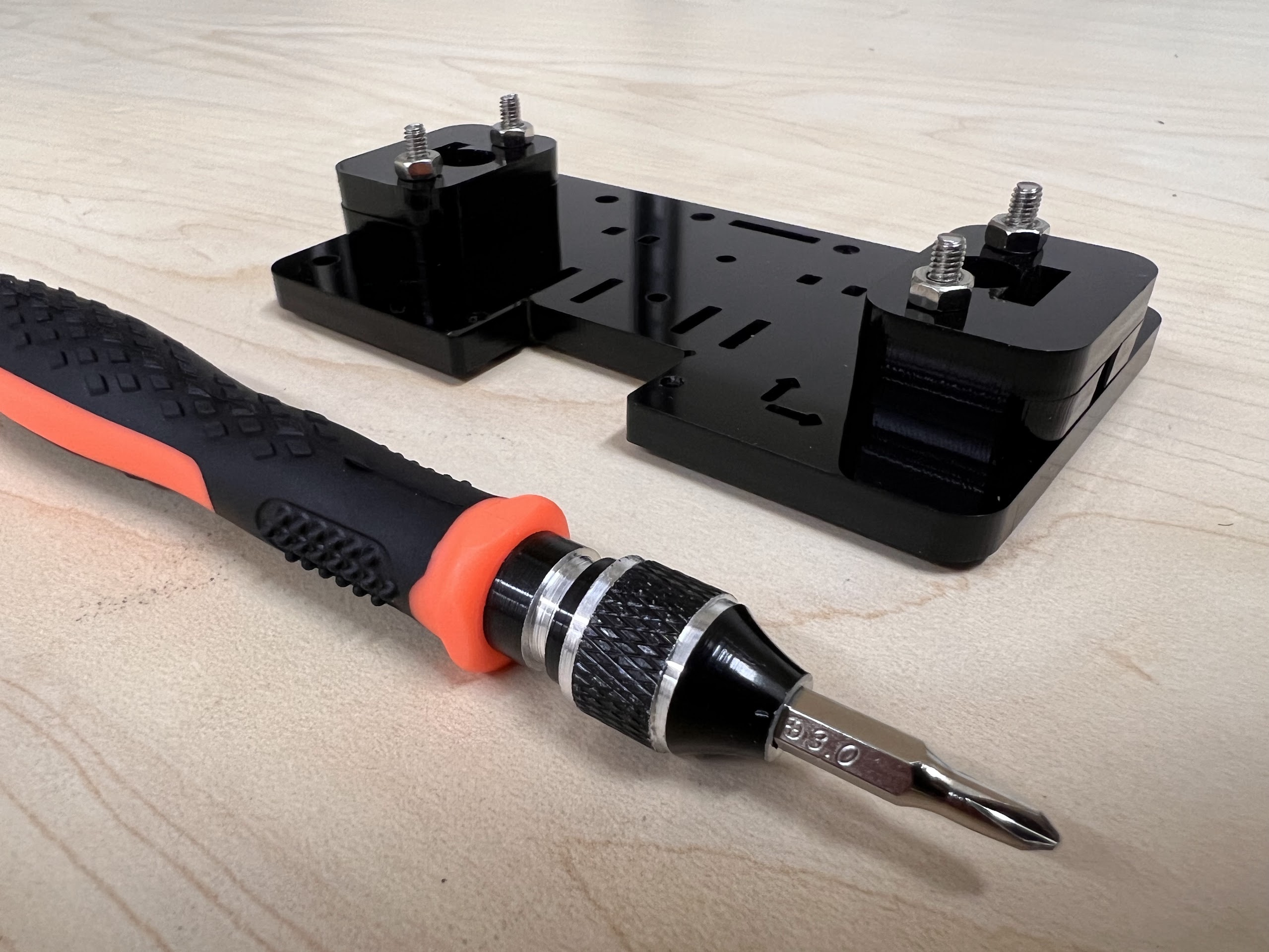
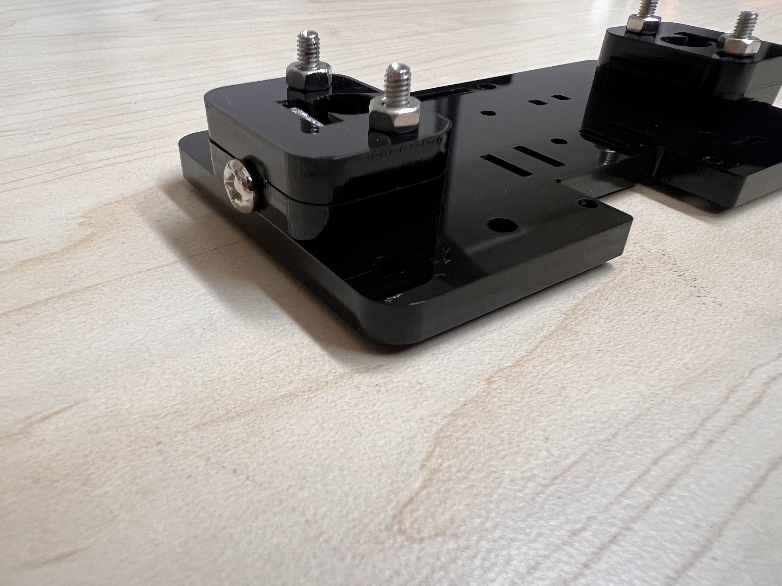
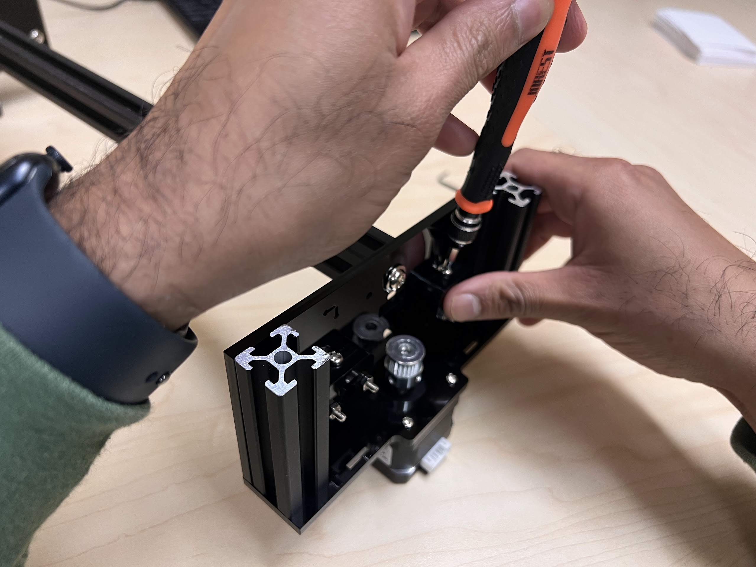
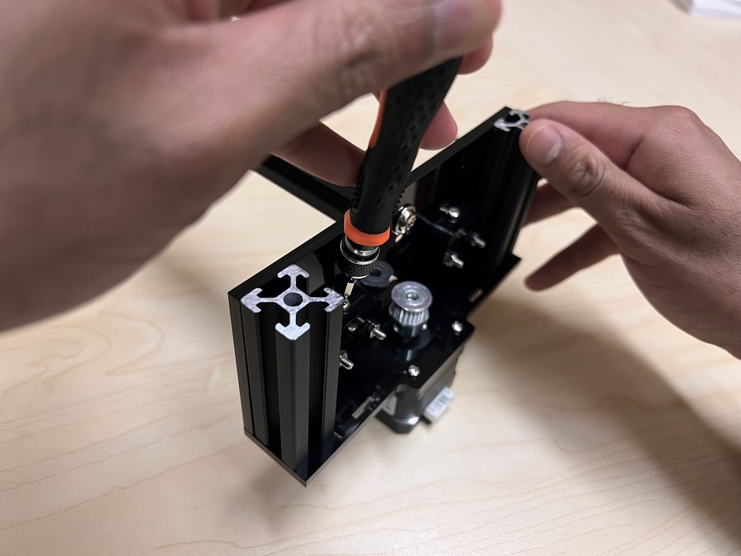
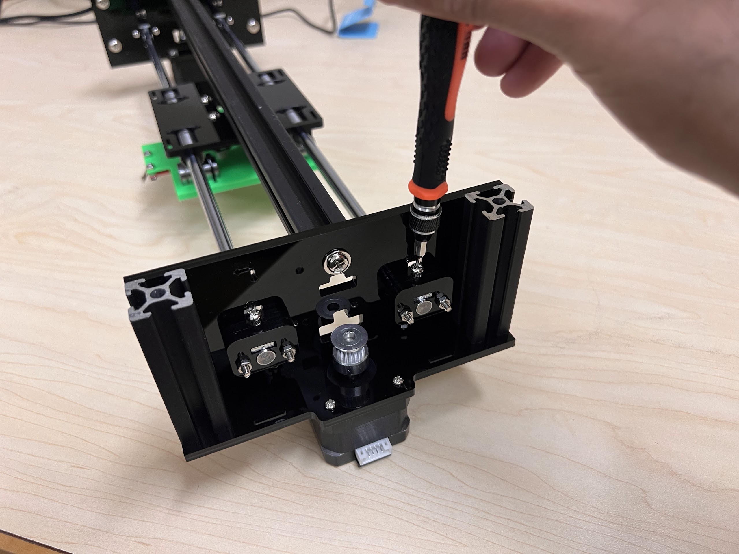
- Using the 3.0 Ph0 Head and the Screwdriver from the Electronics Screwdriver Set:
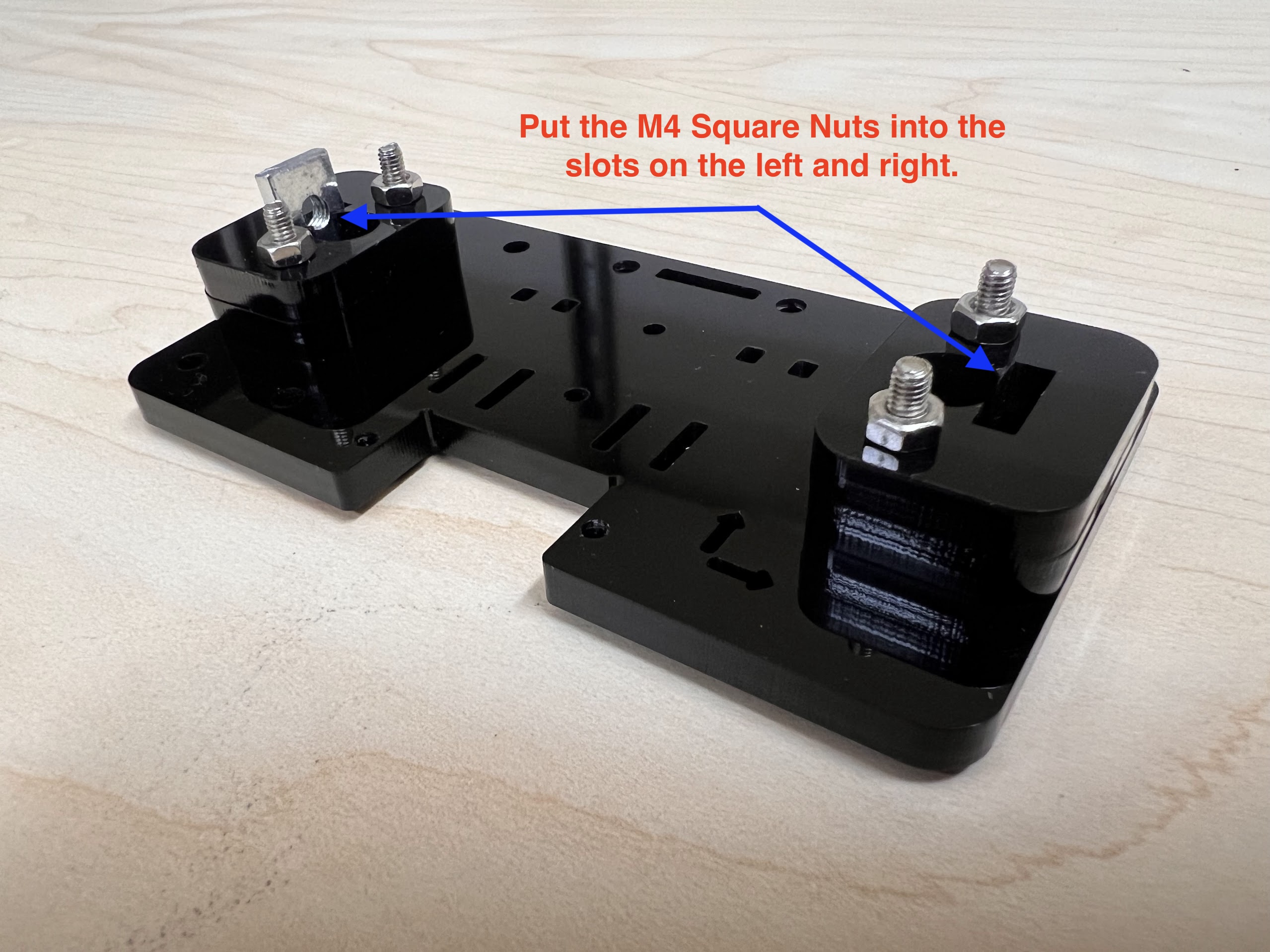
- Put M4 Hex Nuts on Top.
- Hold the Nuts with your hands and tighten the screws from the other side.
- Do not overtighten.
- Execute the Cell Below to Watch a Video of the process.