Please see Version 2 which includes a Flyback Diode in the Circuit. Do not assemble this version of the Valve Controller
Instructions for Assembling Valve Controller using the ESP32 Microcontroller
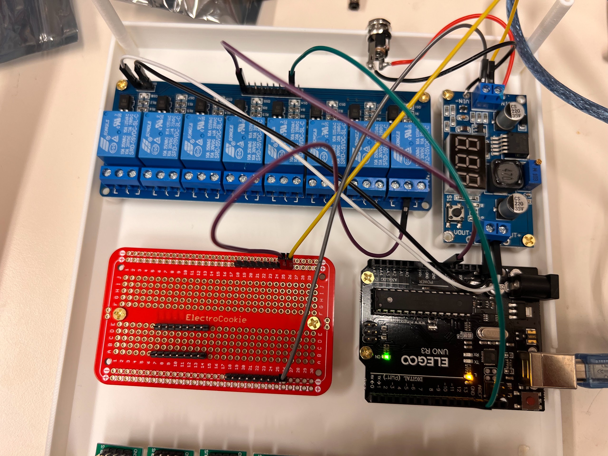
- This notebook is a slightly modified version of our previous version using the Arduino UNO R3 Clone Microcontroller. You can use ESP32 Microcontroller as well if you want.
Brief Description of Purpose and Working Principles:
- We need to a way to control the flow of liquid through the ChronoSeq Device by shutting down or redirecting flow.
- To help control the flow with our computer we need to build a Valve Controller that can switch specific valves ON or OFF when it receives a command from the computer.
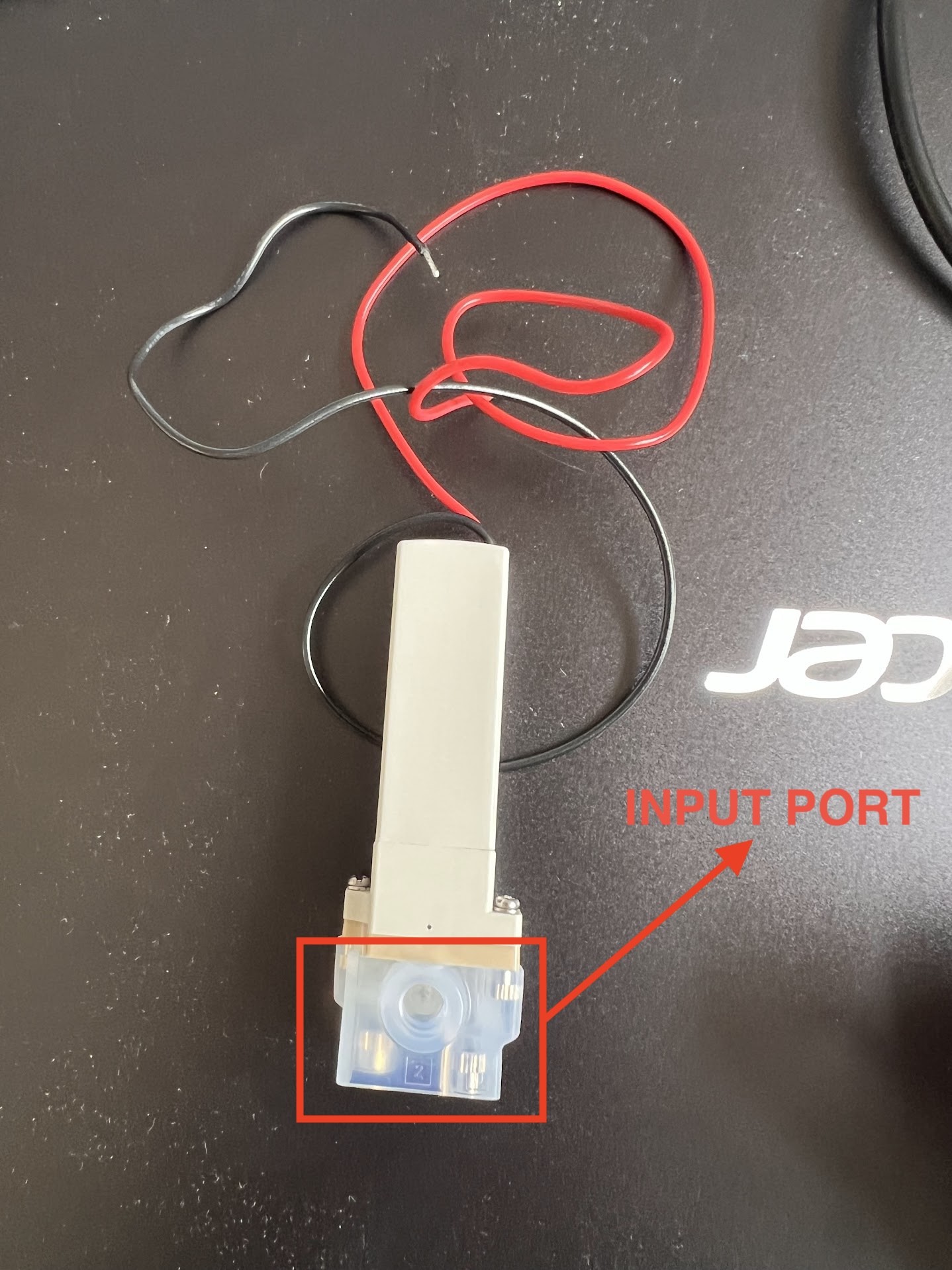
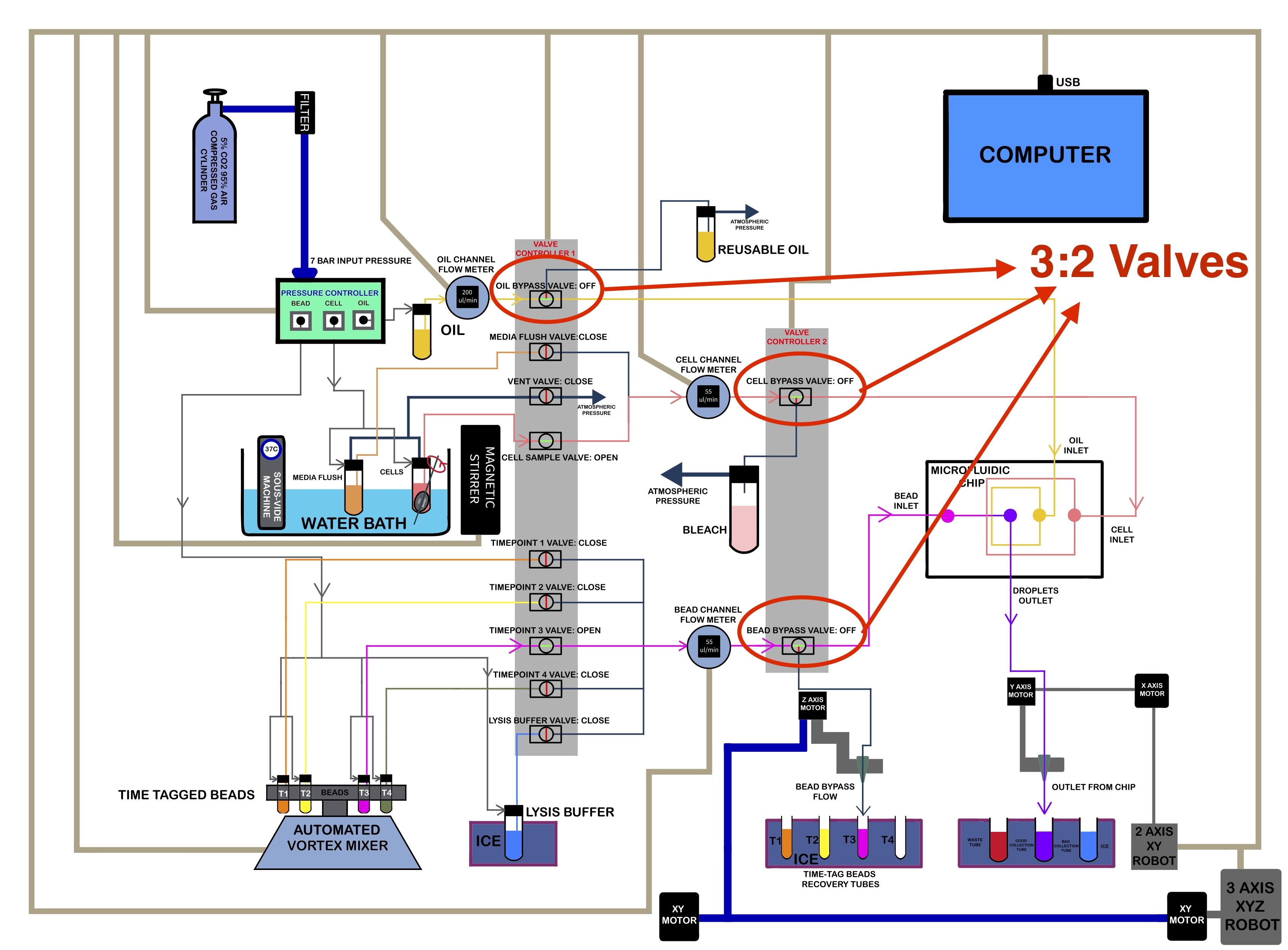
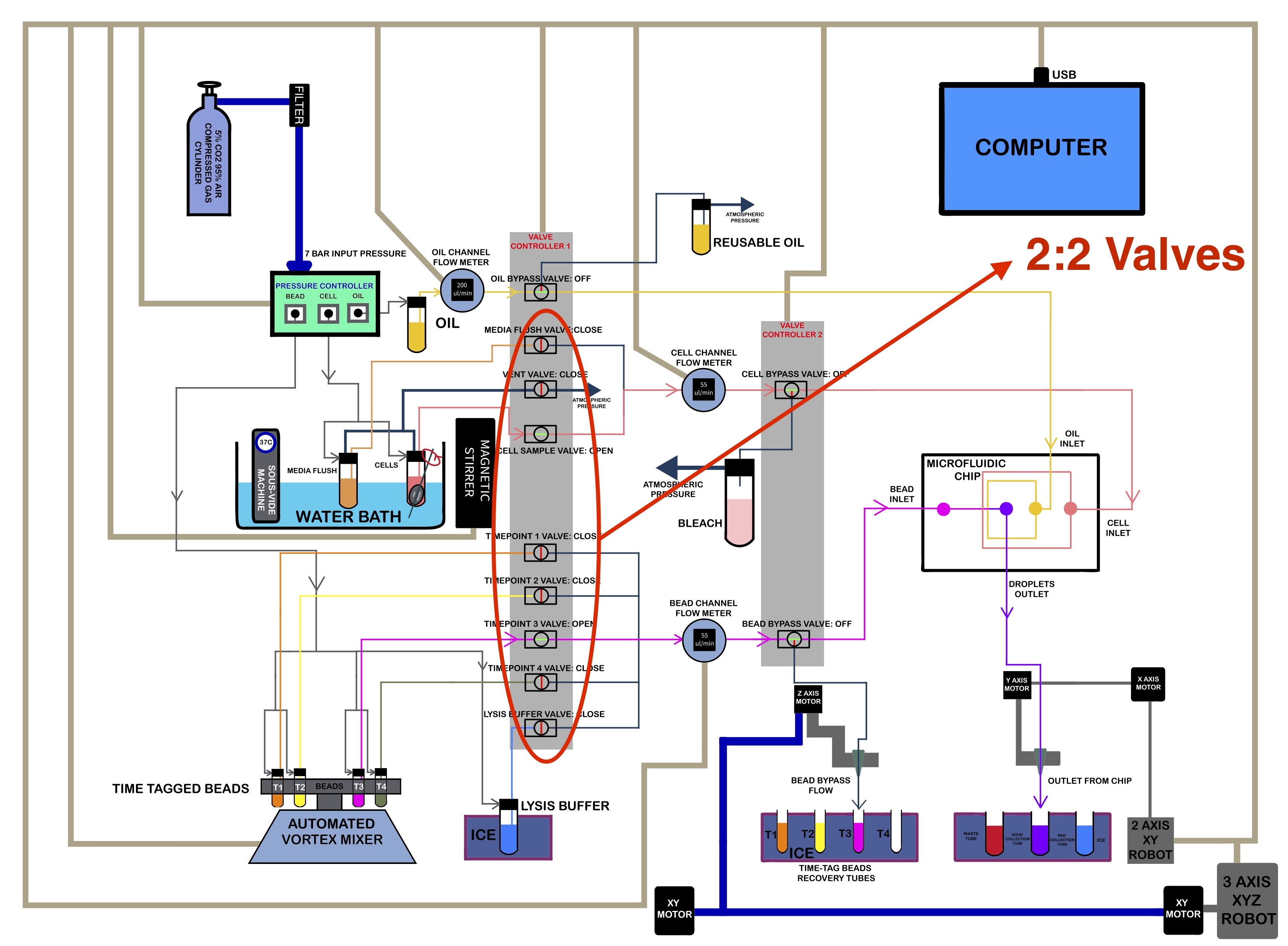
- The SMC Valves we have selected for our device can be 2:2 Valves or 3:2 Valves.
- 2:2 Valves Turn Flow ON or OFF. Most of these will be used to control flow from Individual Reservoirs.
- 3:2 Valves Redirect Flow from the Input Port to the Main or Bypass Port. We use these as Bypass Valves for Controlling flow into the Microfluidic Chip for each Channel: Cells, Beads and Oil.
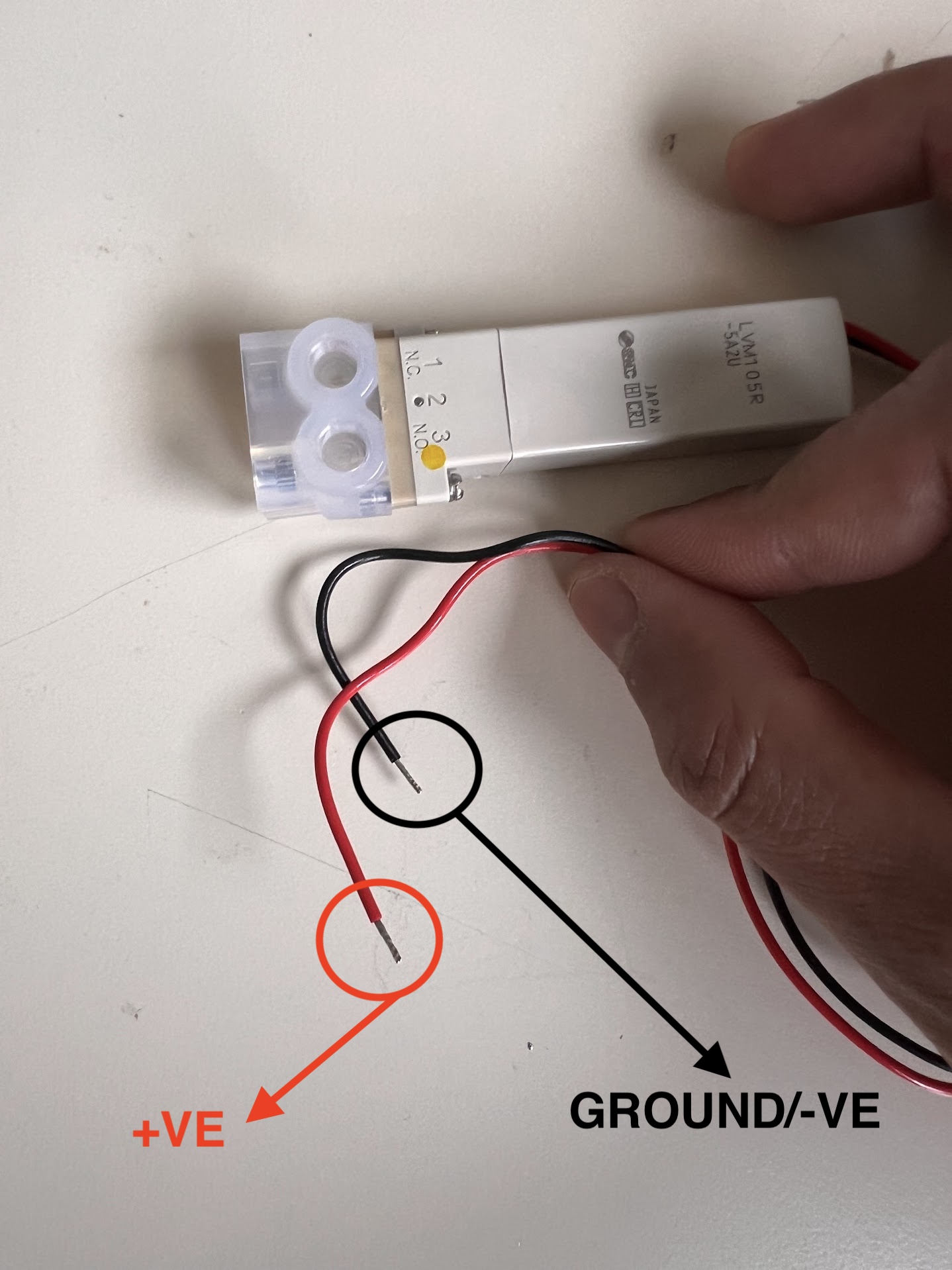
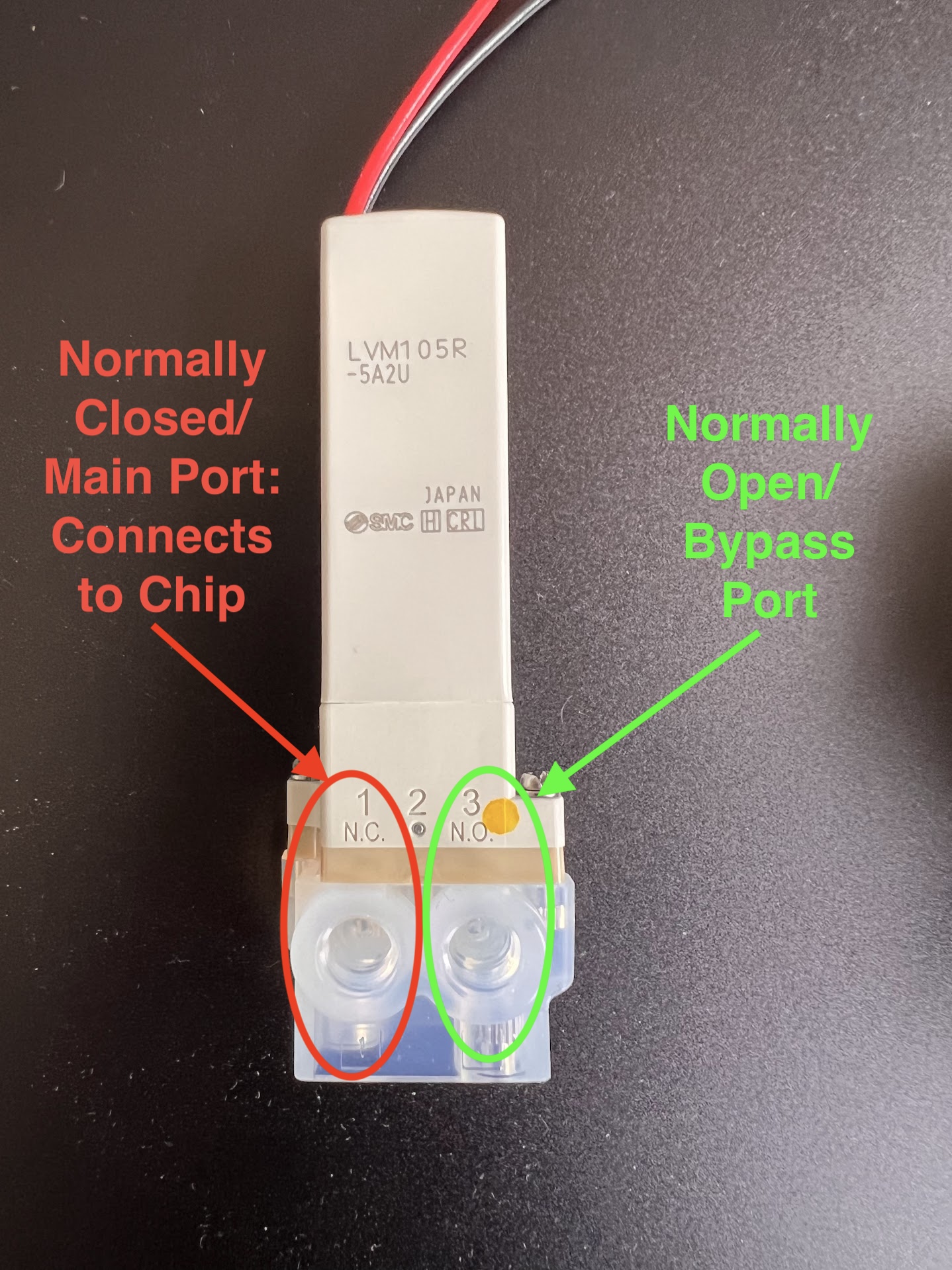
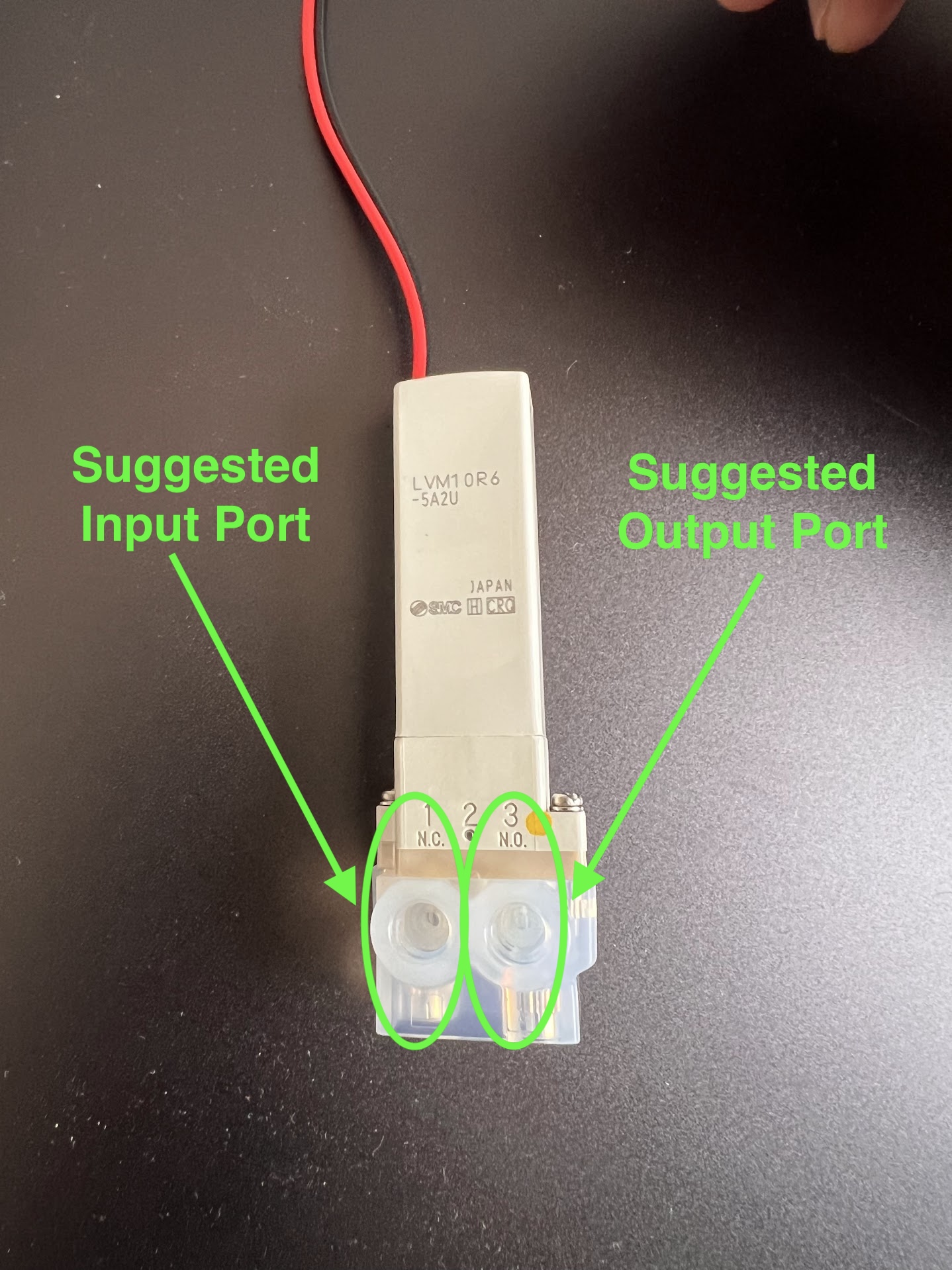
- The 2:2 SMC Valves we have purchased are Normally Closed (NC). Meaning liquid will only flow through them when they are powered ON.
- The 3:2 Valves allow flow from:
- The Input Port to the Bypass port when powered OFF. The Bypass port is therefore called the Normally Open (NO) Port.
- You can identify the NO Port by Looking for the NO Symbol on the Valve near the Port.
- The Valve allows flow from the Input port to the Main port only when powered ON. This port is therefore called the Normally Closed (NC) Port.
- You can identify the NC Port by Looking for the NC Symbol on the Valve near the Port.
- The 3:2 Valves can be converted into 2:2 NC or 2:2 NO Valves by blocking either the NC or NO Port using a Delrin Plug.
| 3:2 Valve Input Port | 3:2 NC and NO Port Locations | 2:2 Valve Suggested Input and Output Ports |
|---|---|---|
 |
 |
 |
| Location of 3:2 Bypass Valves in Schematic | Location of 2:2 Valves in Schematic |
|---|---|
 |
 |
Ordering Information for SMC Valves
- SMC Valves are Highly Configurable and the exact product number represents this configuration.
- For Example this website allows you to generate a product number before ordering.
- Make sure the Chemicals being used for your application are compatible with the Wetted materials in your Valve Configuration.
- We will be ordering the LVM10 Series of Valves.
- The Following product numbers and Quantities were ordered for the two types for Valves:
- 2:2 Valves: LVM10R6-5A2U . Quantity : 30 Units
- 22 Units are needed in the Version of the ChronoSeq Device with 16 Timepoint Reservoirs.
- The remaining 8 were kept as backup replacements.
- You can order only 22 Valves if you want to save some money.
- Only 18 Valves are necessary if your device has 12 Timepoint Reservoirs.
- 3:2 Valves: LVM105R-5A2U . Quantity : 5 Units
- 3 Units are needed in the Current Version of the ChronoSeq Device.
- The remaining 2 were kept as backup replacements.
- You can order only 3 Valves if you want to save some money.
- 2:2 Valves: LVM10R6-5A2U . Quantity : 30 Units
- SMC has many global suppliers and your local supplier might vary.
- Different suppliers offer different prices.
- Its best to find the most competitive local supplier for your area.
- You can use this website to help you locate a supplier.
- We ordered our valves from Bay Advanced Technologies located in Orange County, CA.
- Its best to call them to place an order. Their number is +1 714-241-1031 .
- You should also email Monica(mgparra@bayat.com) or Derek(dloe@bayat.com) if they still work there.
- You can also call (+1 213-476-3863) or email Colby(cchristy@bayat.com), a local account Manager in San Diego.
- We payed by providing our Credit Card Number over the phone.
- Both the 3:2 and 2:2 Valves Cost 81.60USD Each in April 2024.
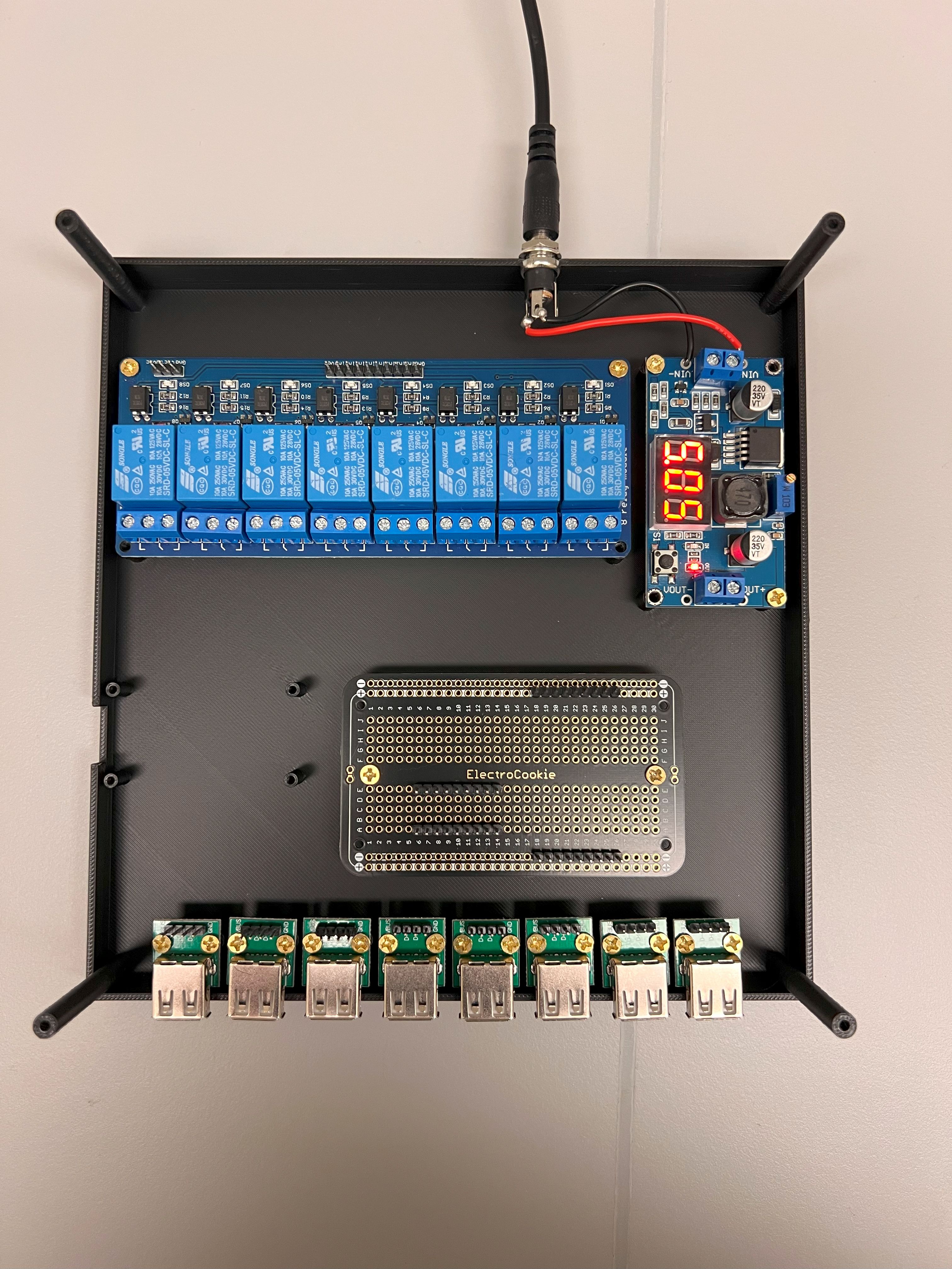
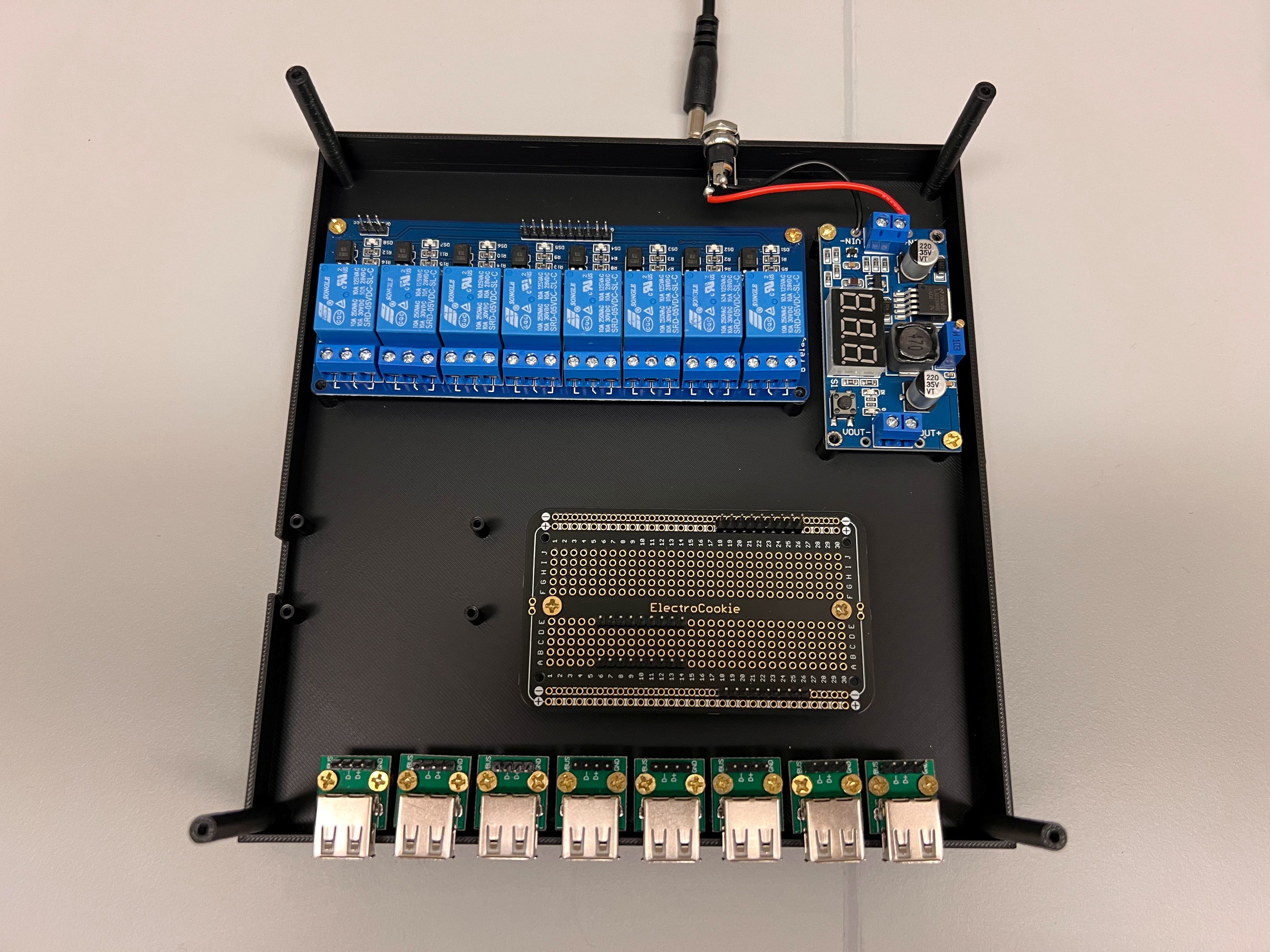
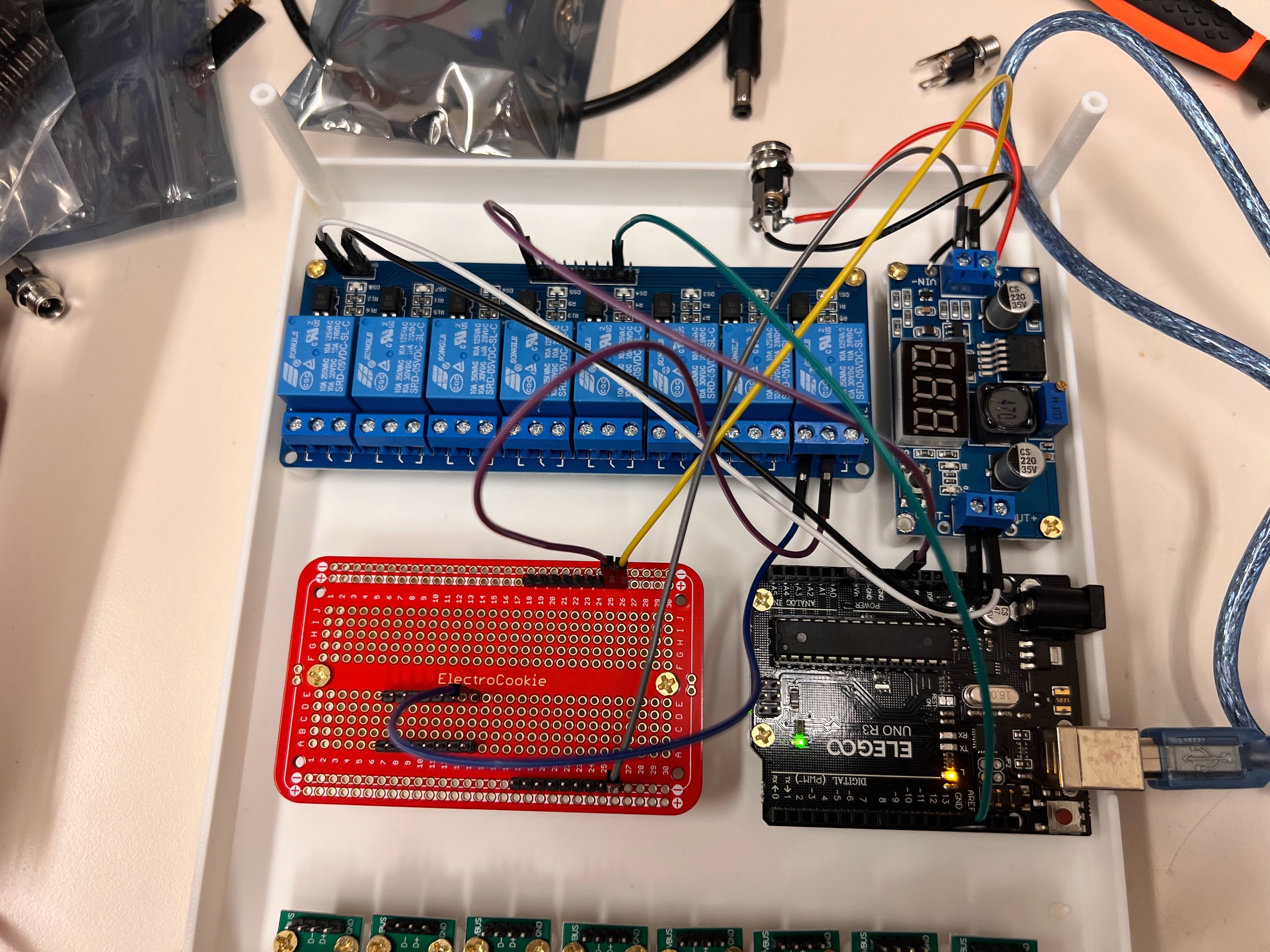
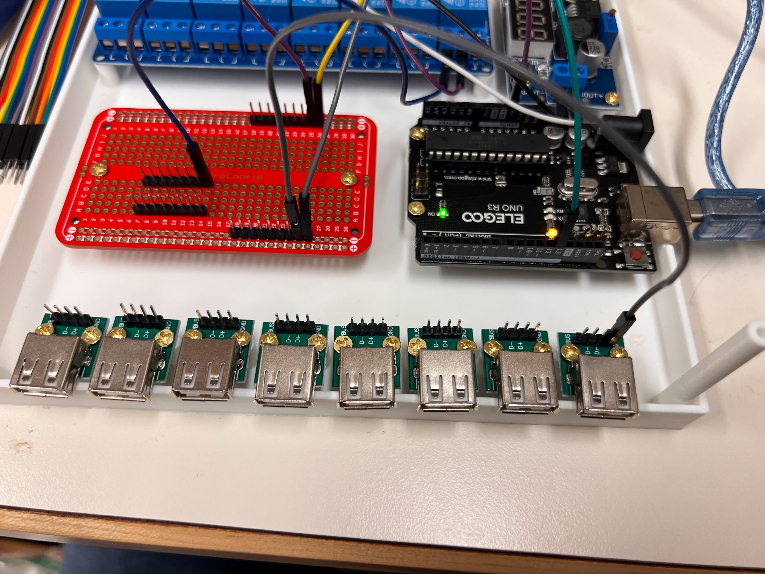
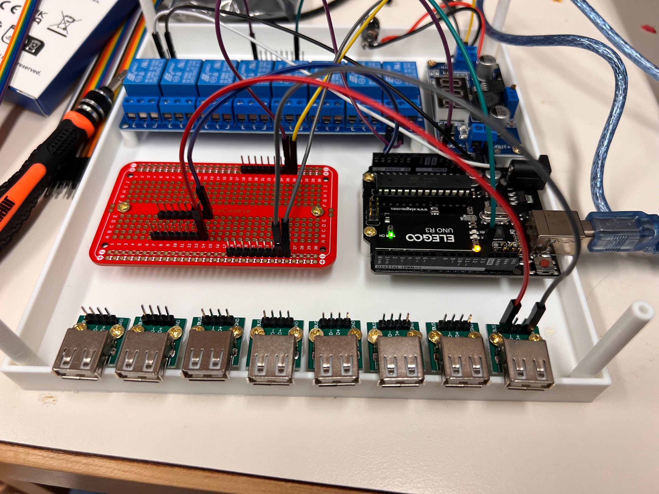
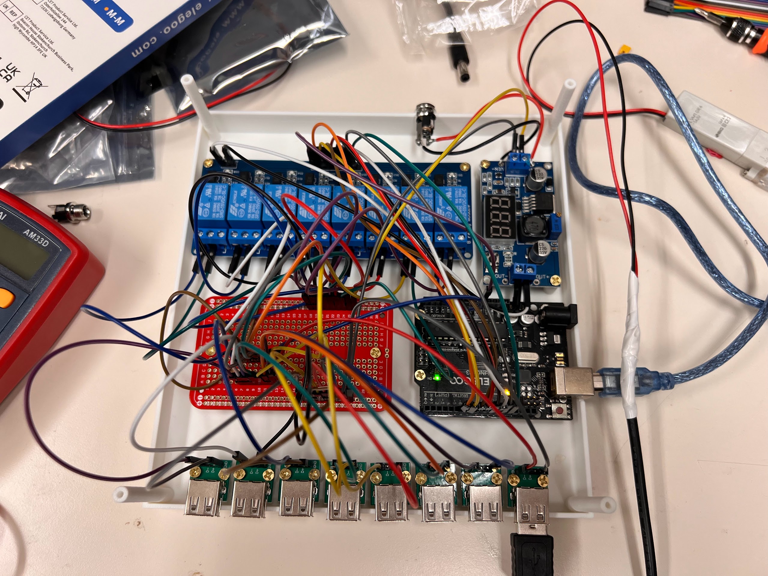
Overview of Valve Controller Design
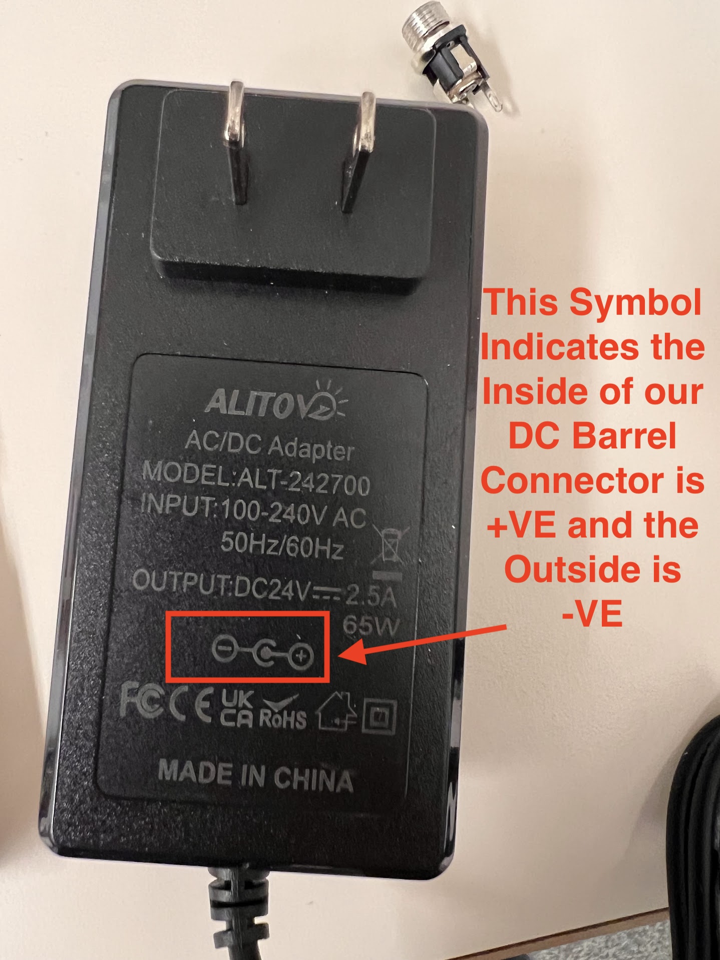
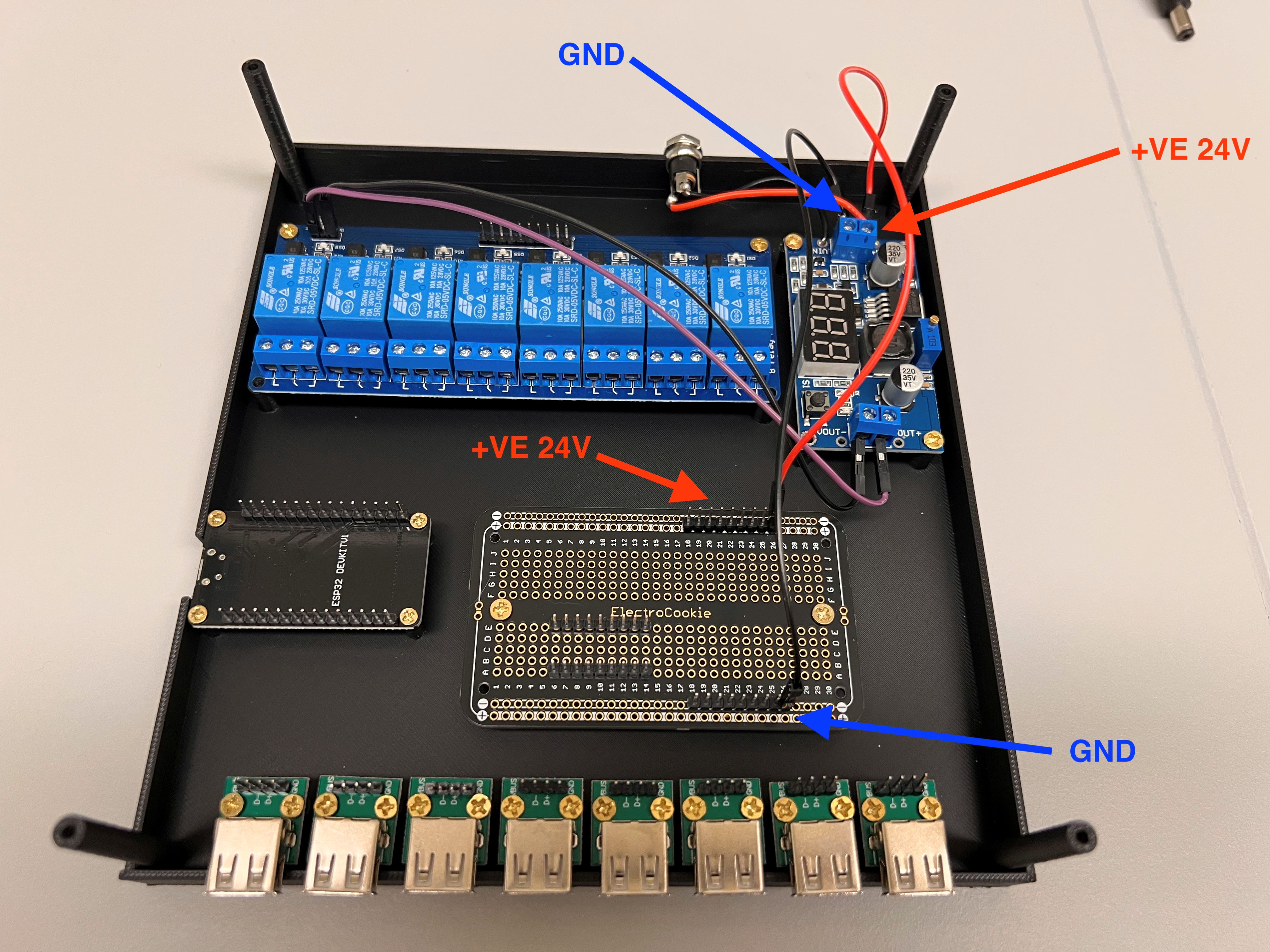
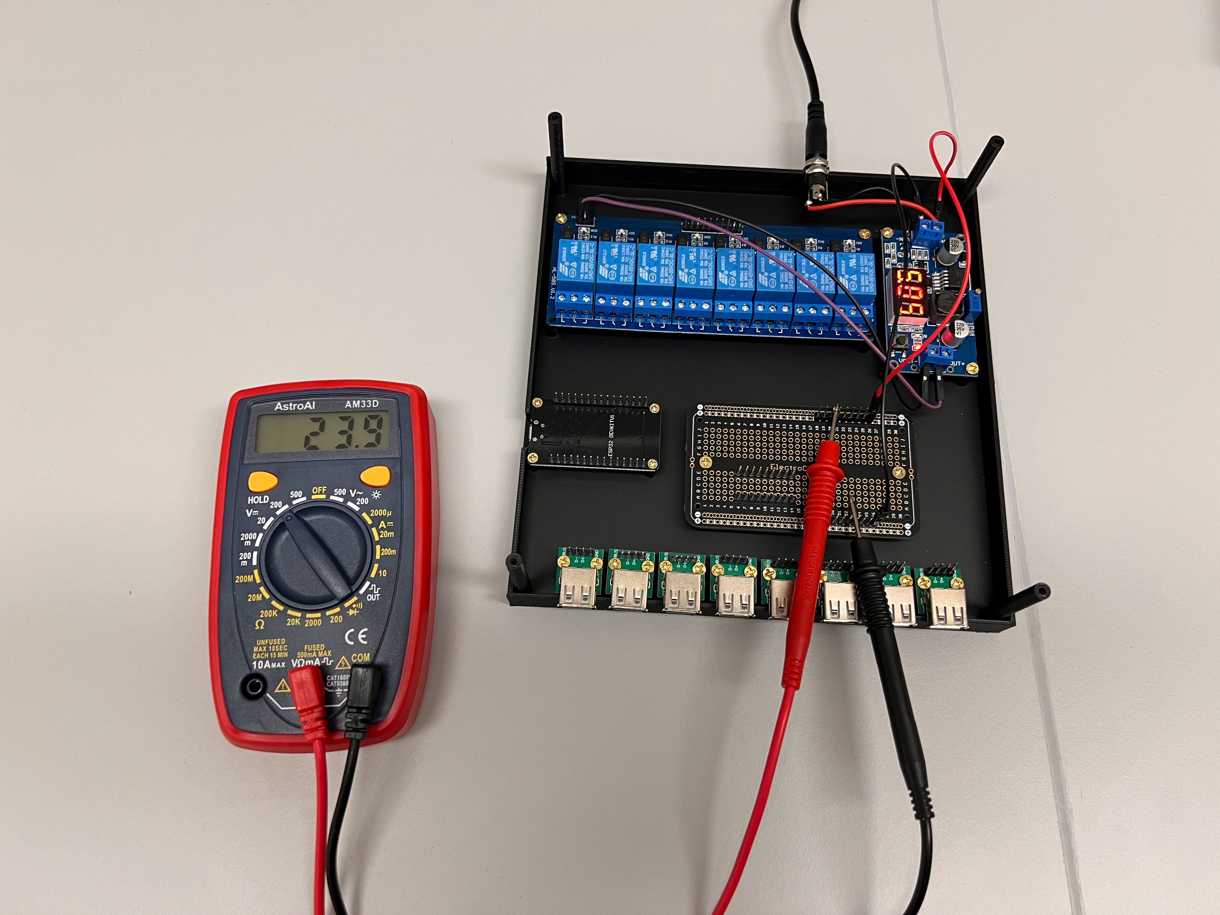
- Both Valves require 24V DC Current to Turn ON and Consume about 1.5W of Power or 60mA of Current.
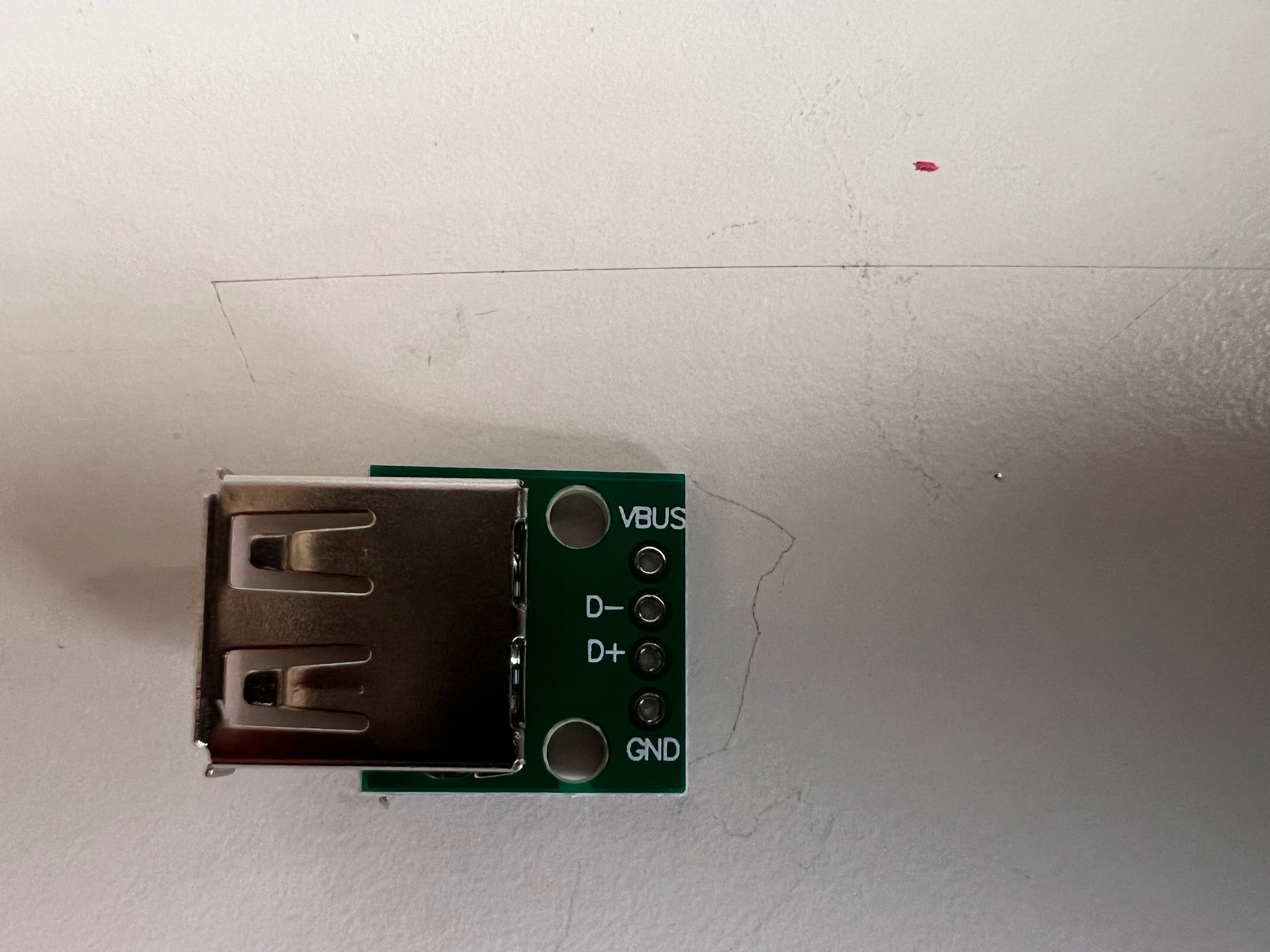
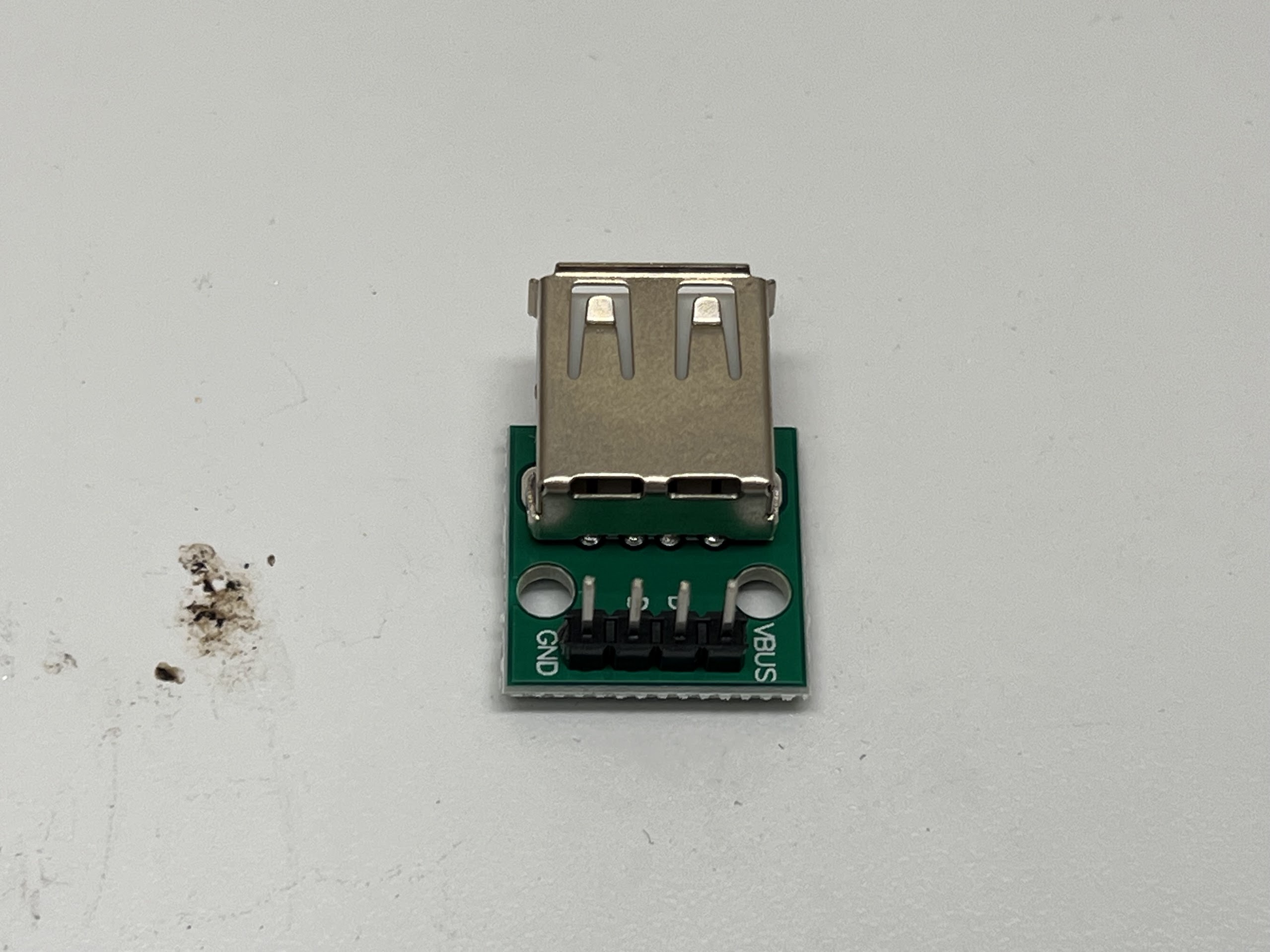
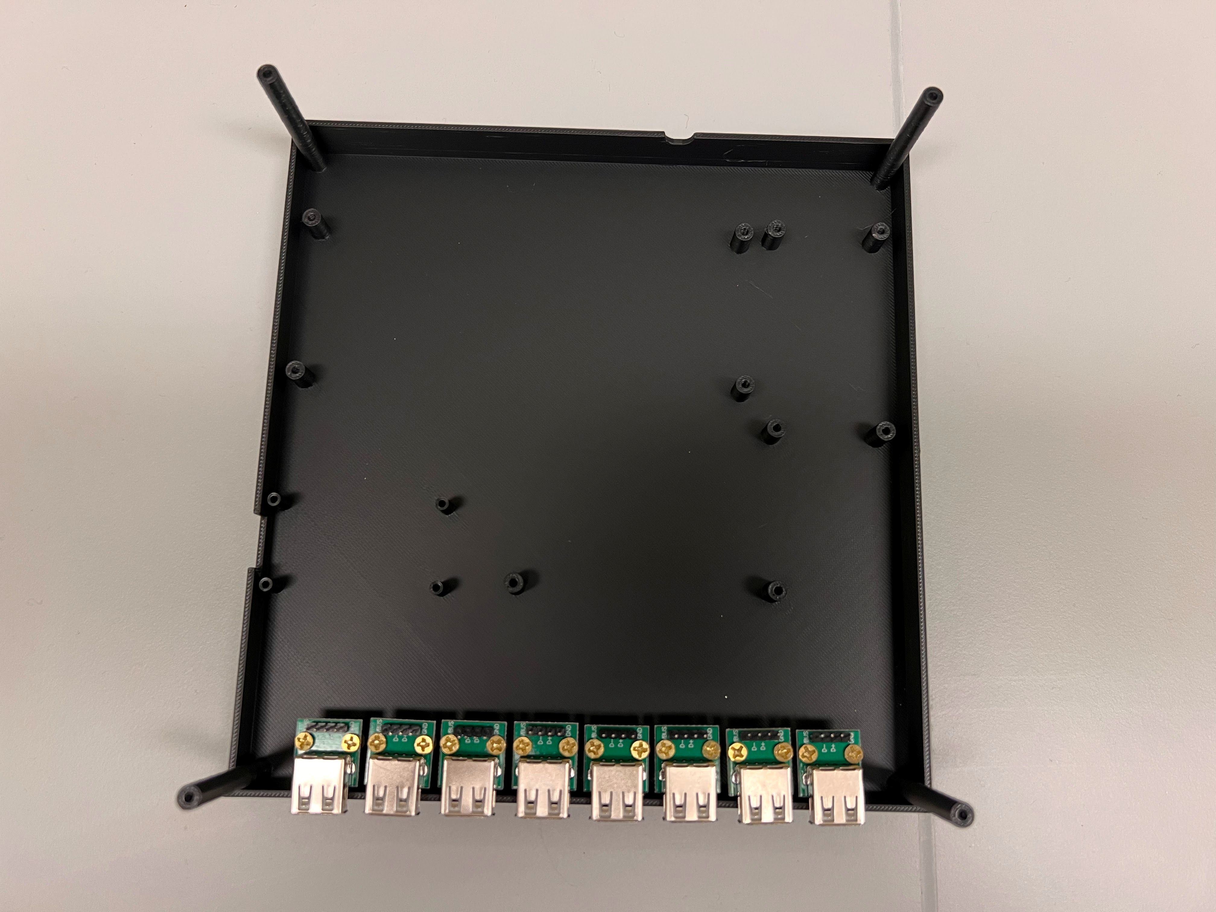
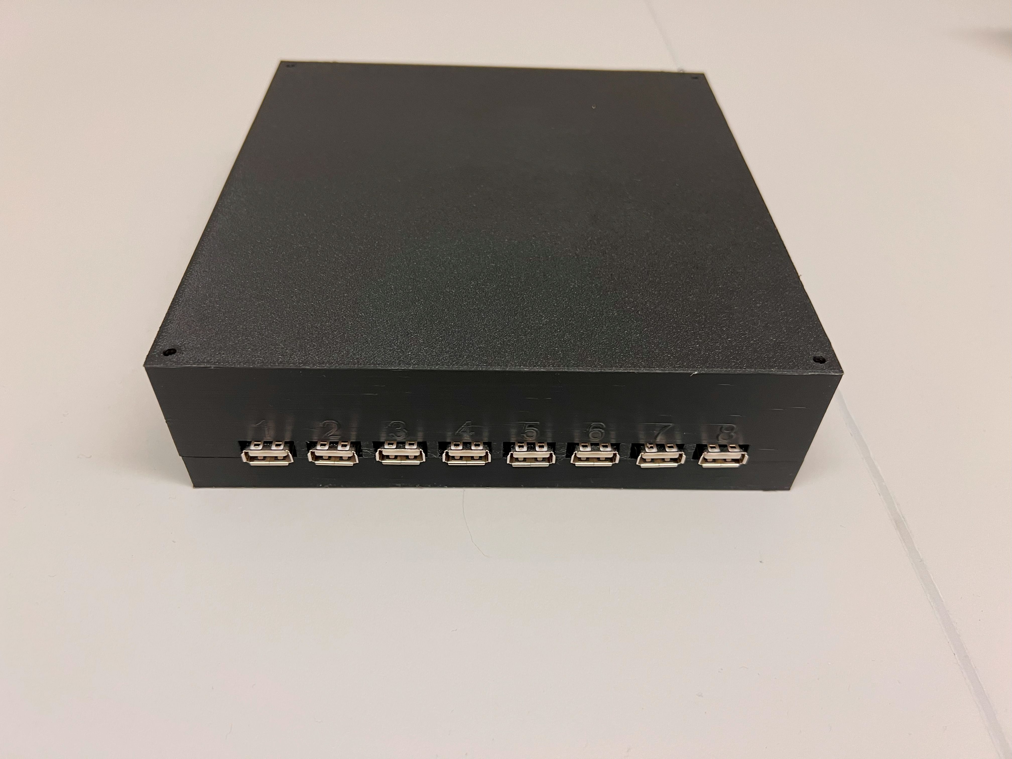
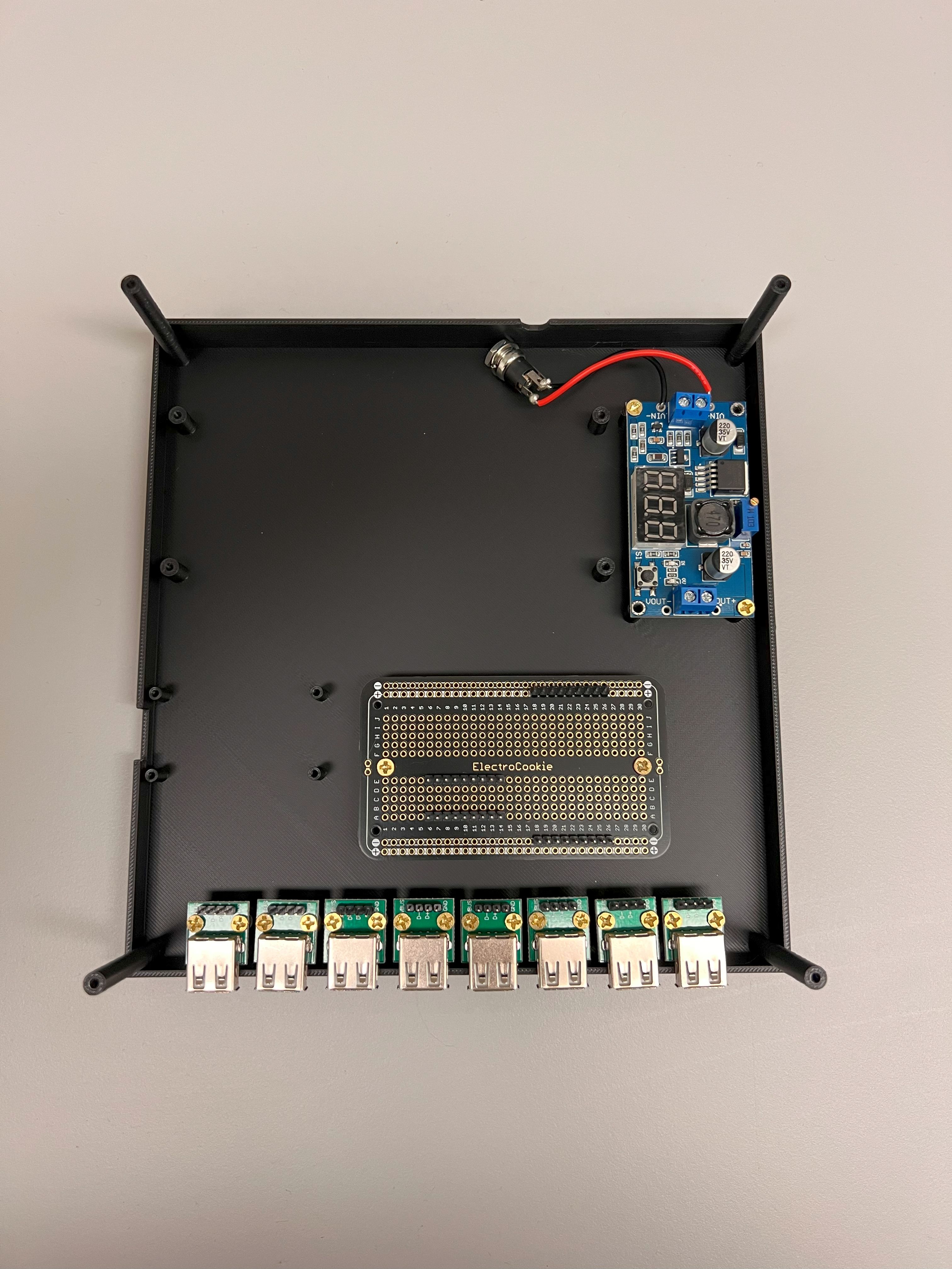
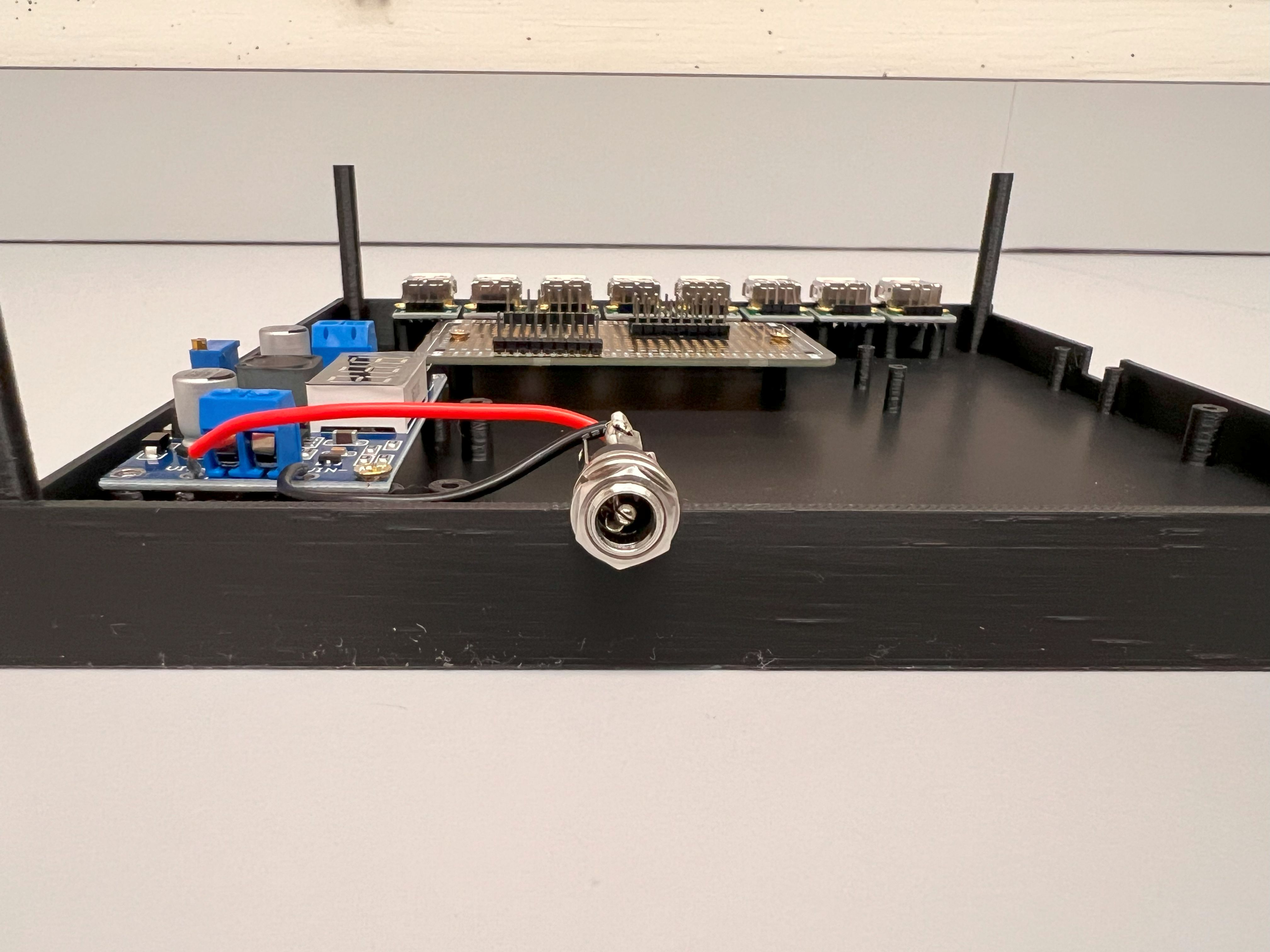
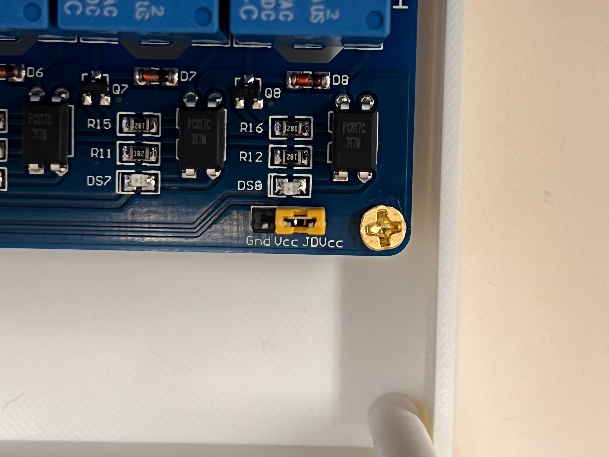
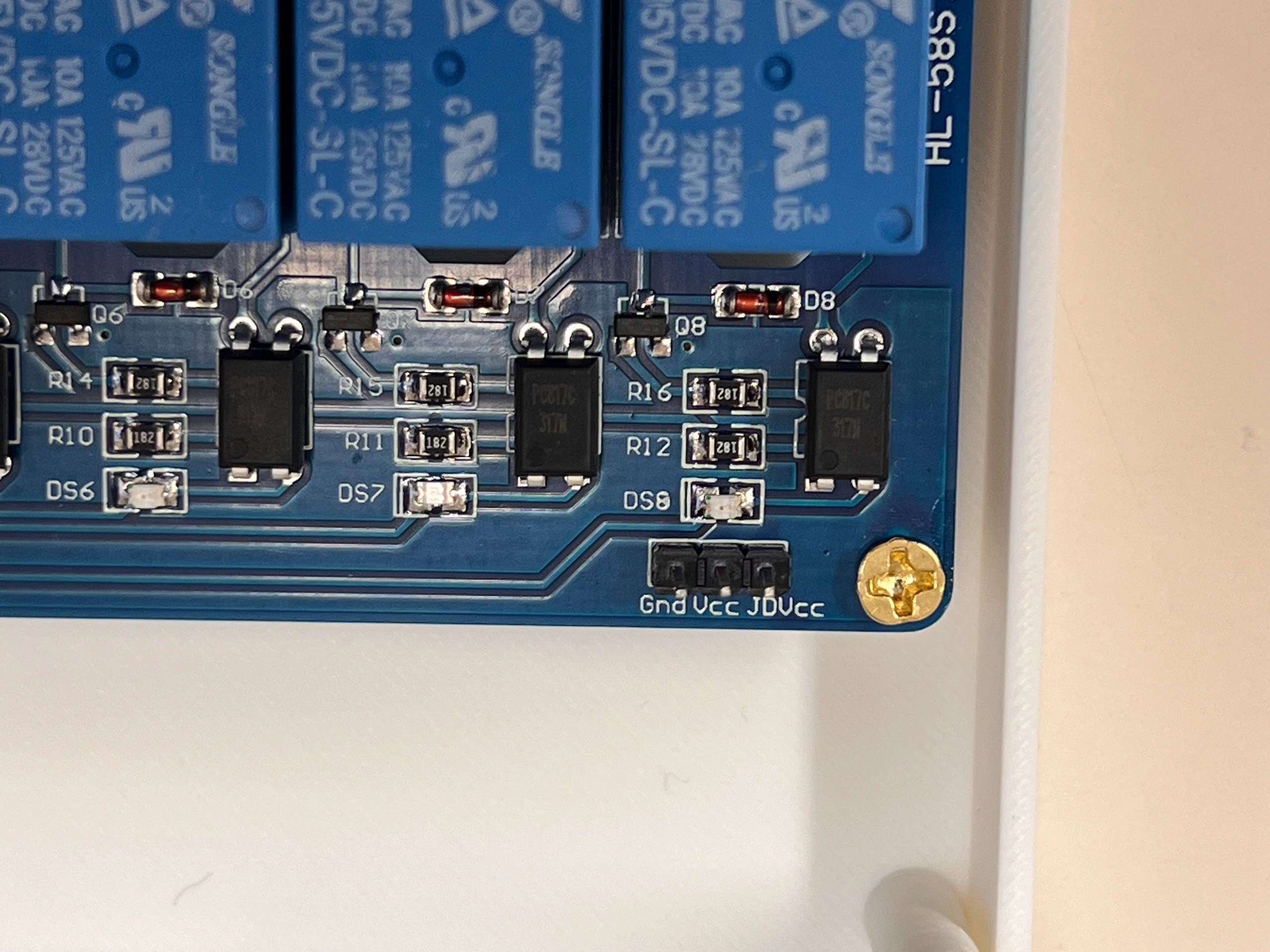
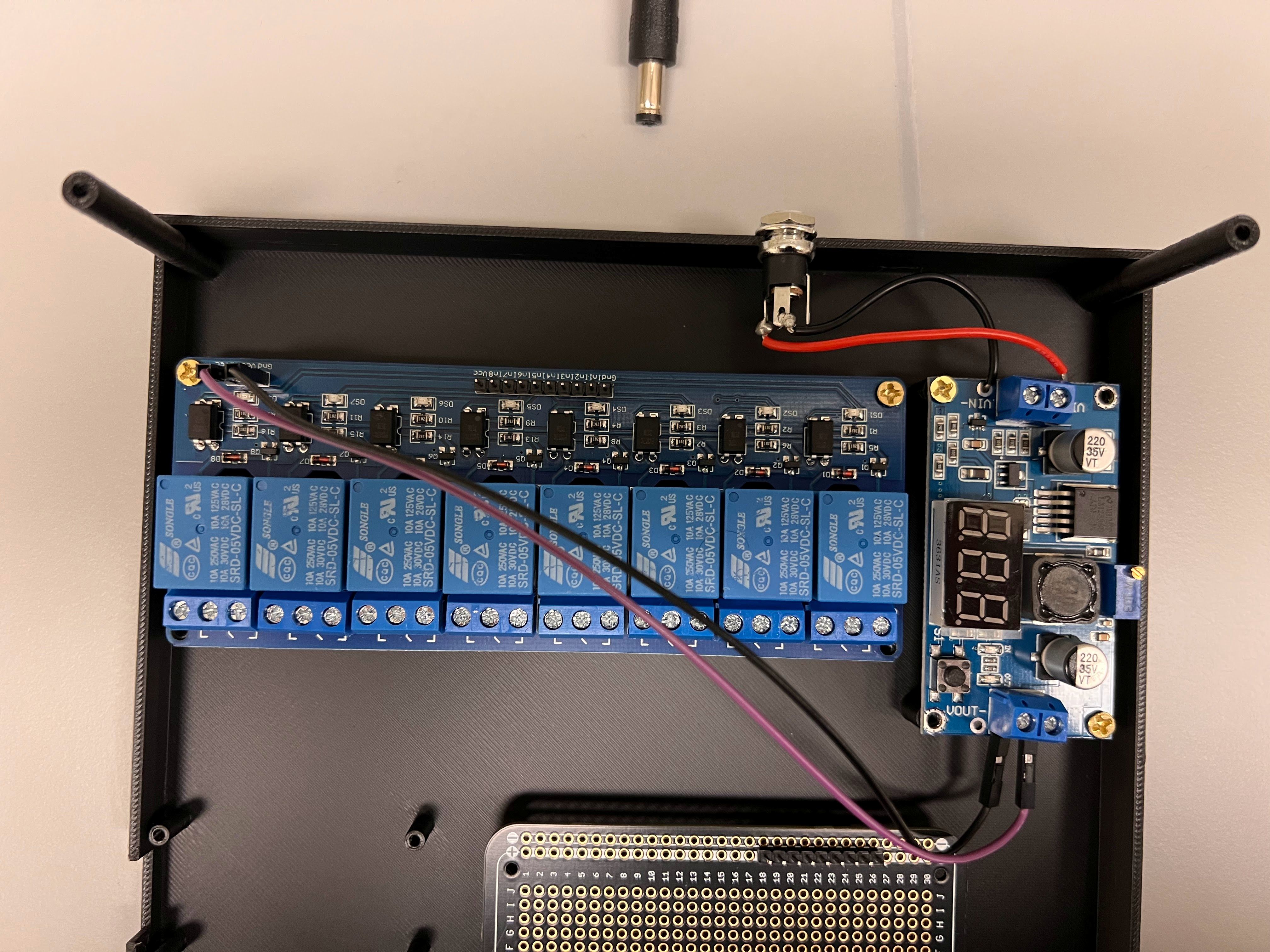
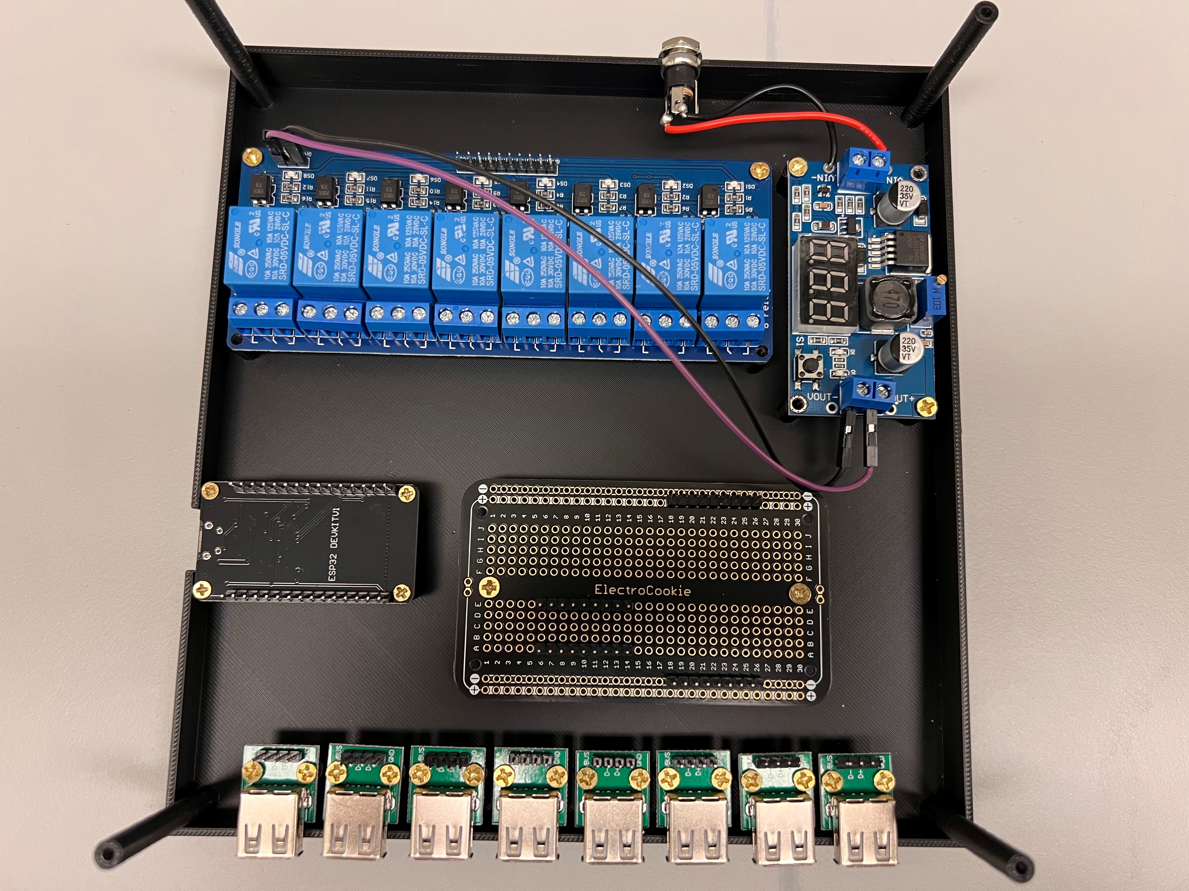
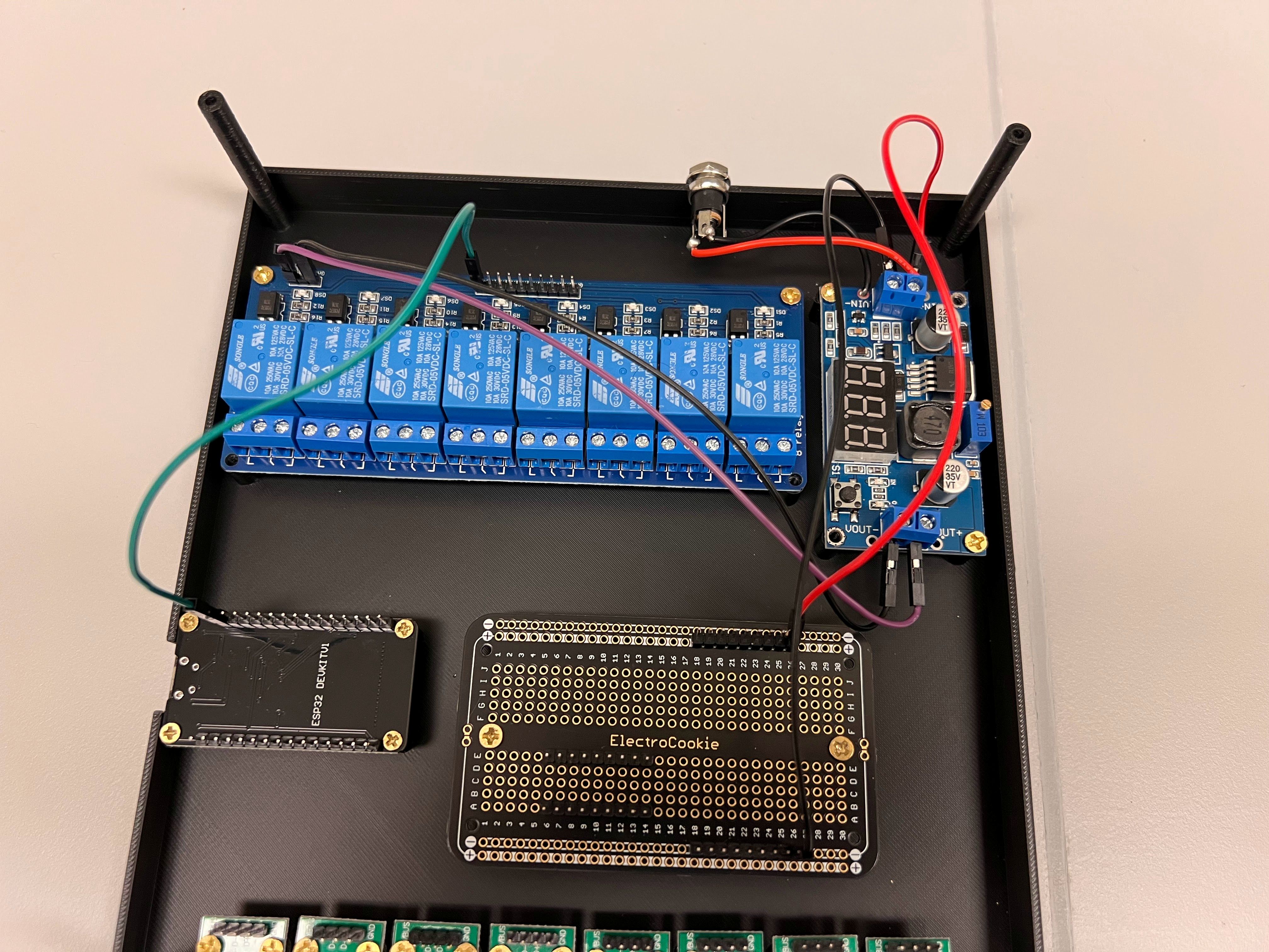
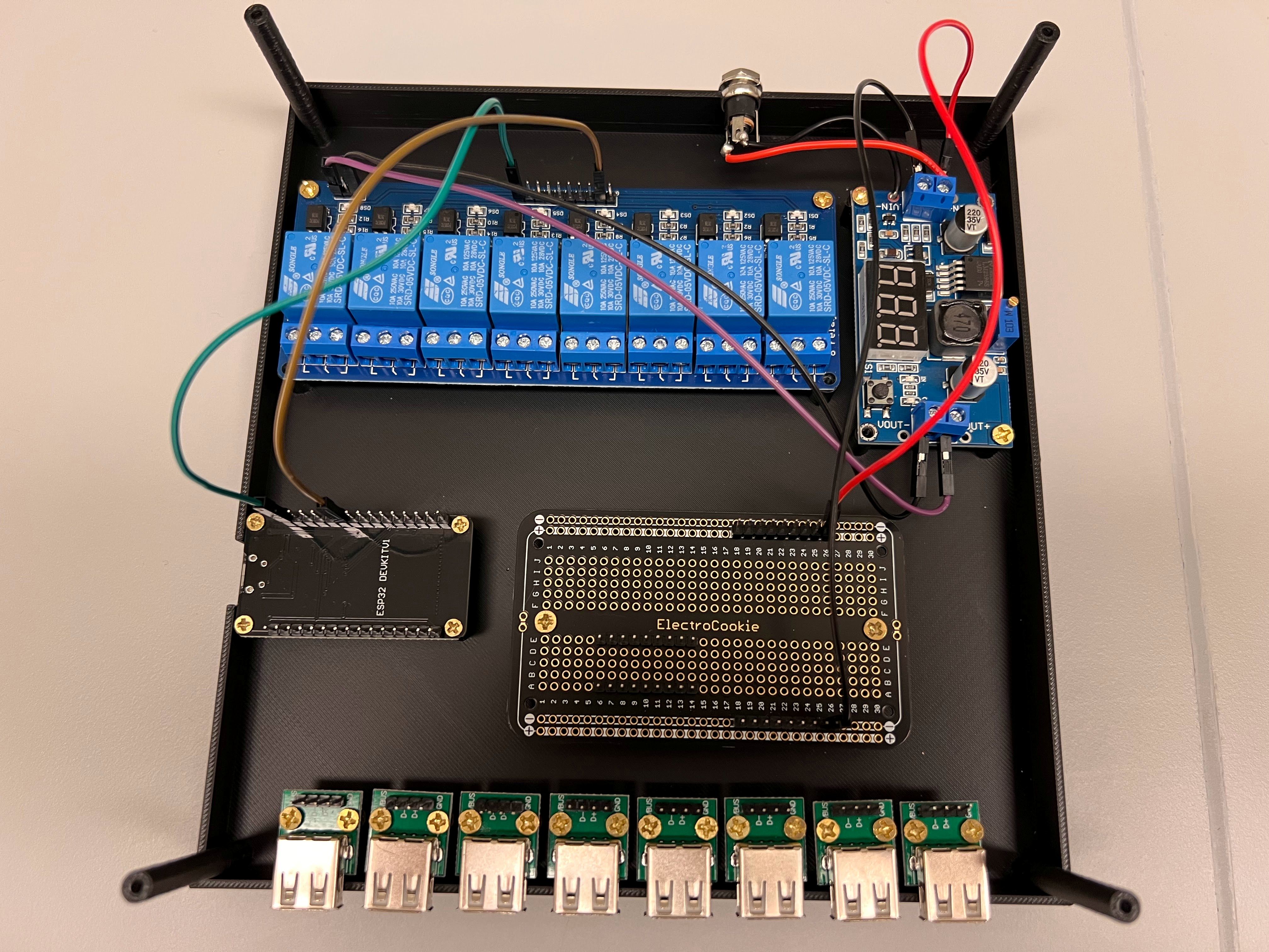
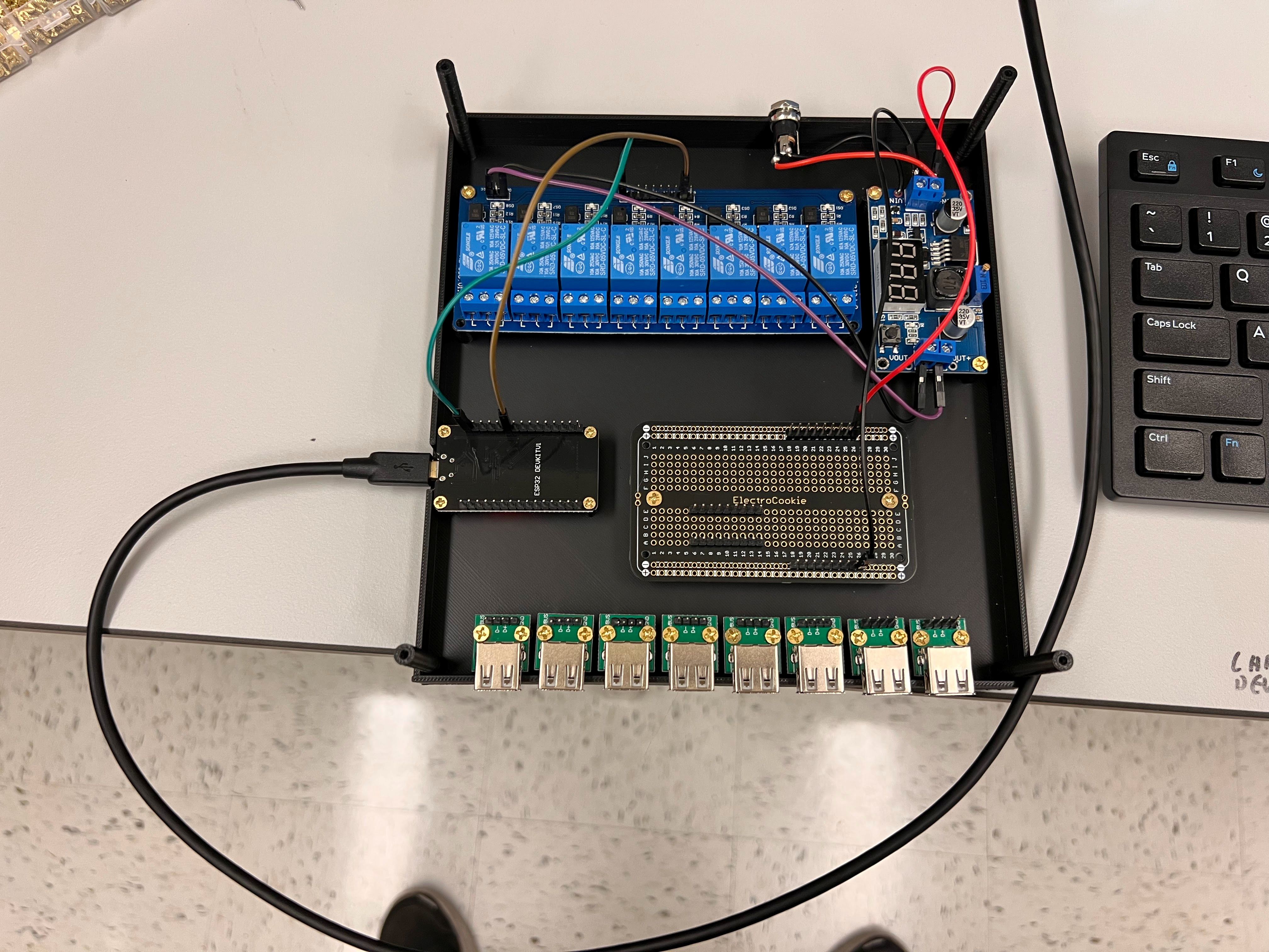
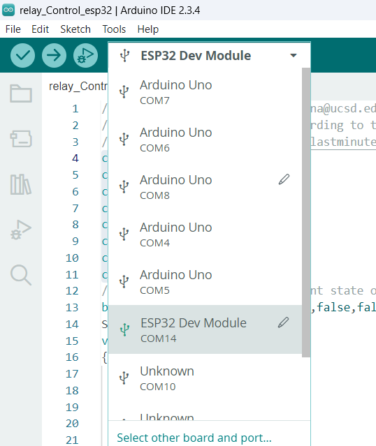
- We will be using a 8-Channel Relay Board Connected to an ESP-WROOM-32 Microcontroller to Control the Flow of Current to the Valves.
- Here is a great Youtube video that explains how this works.
- The 8-Channel Relay requires an Optically Isolated 5V DC Power Supply.
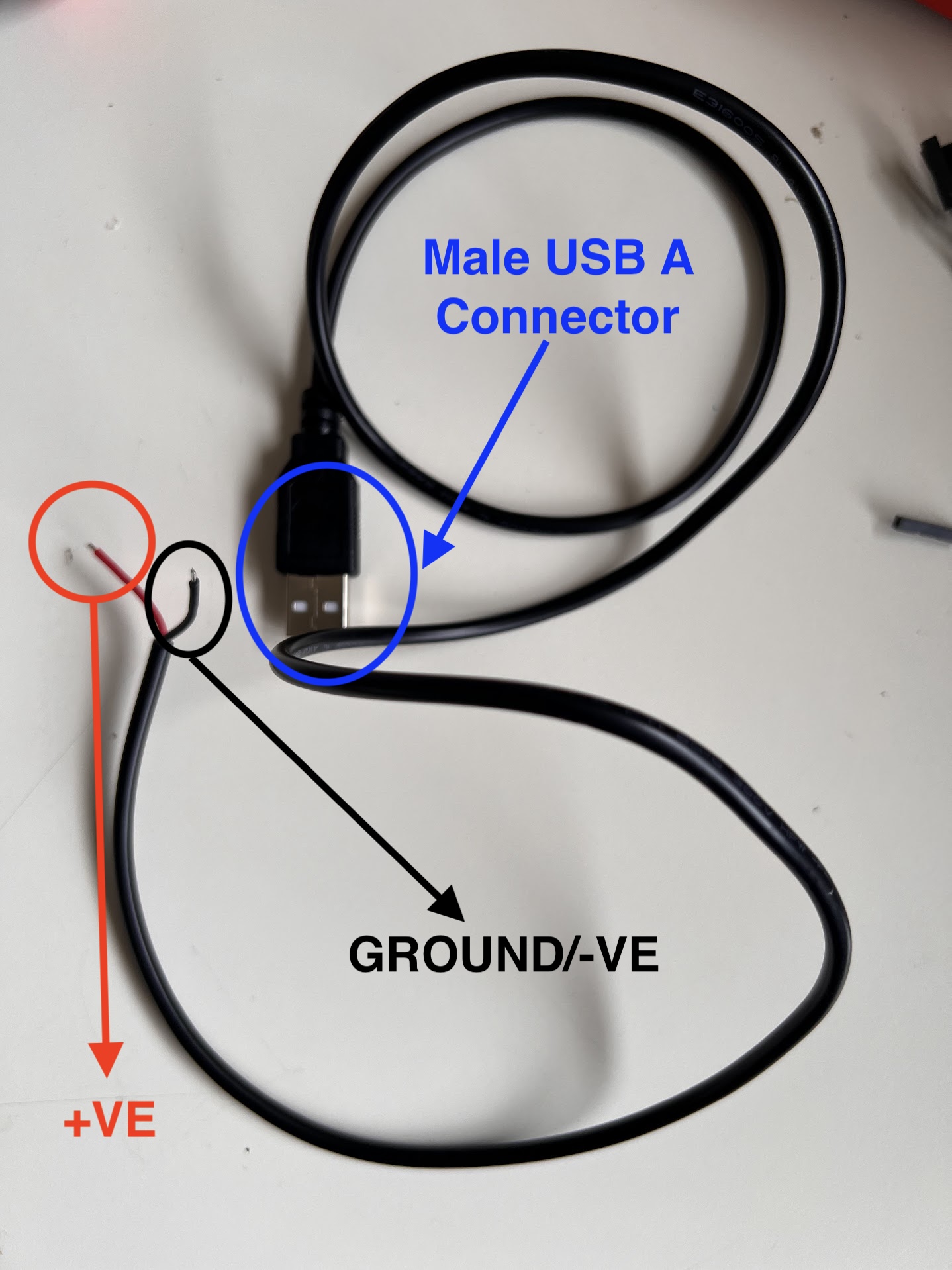
- The ESP-WROOM-32 Microcontroller can be operated using the Power from the USB Port Alone.
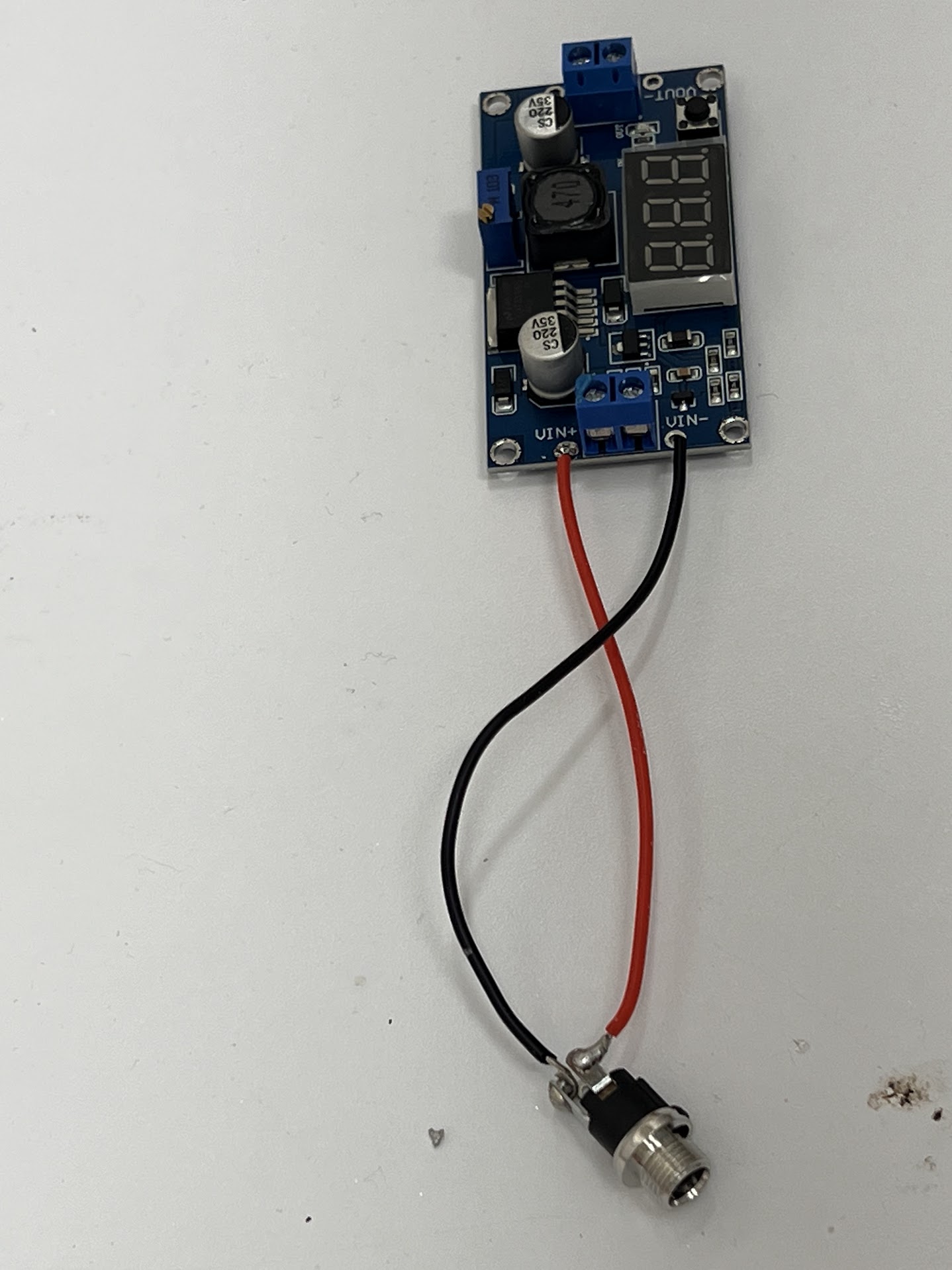
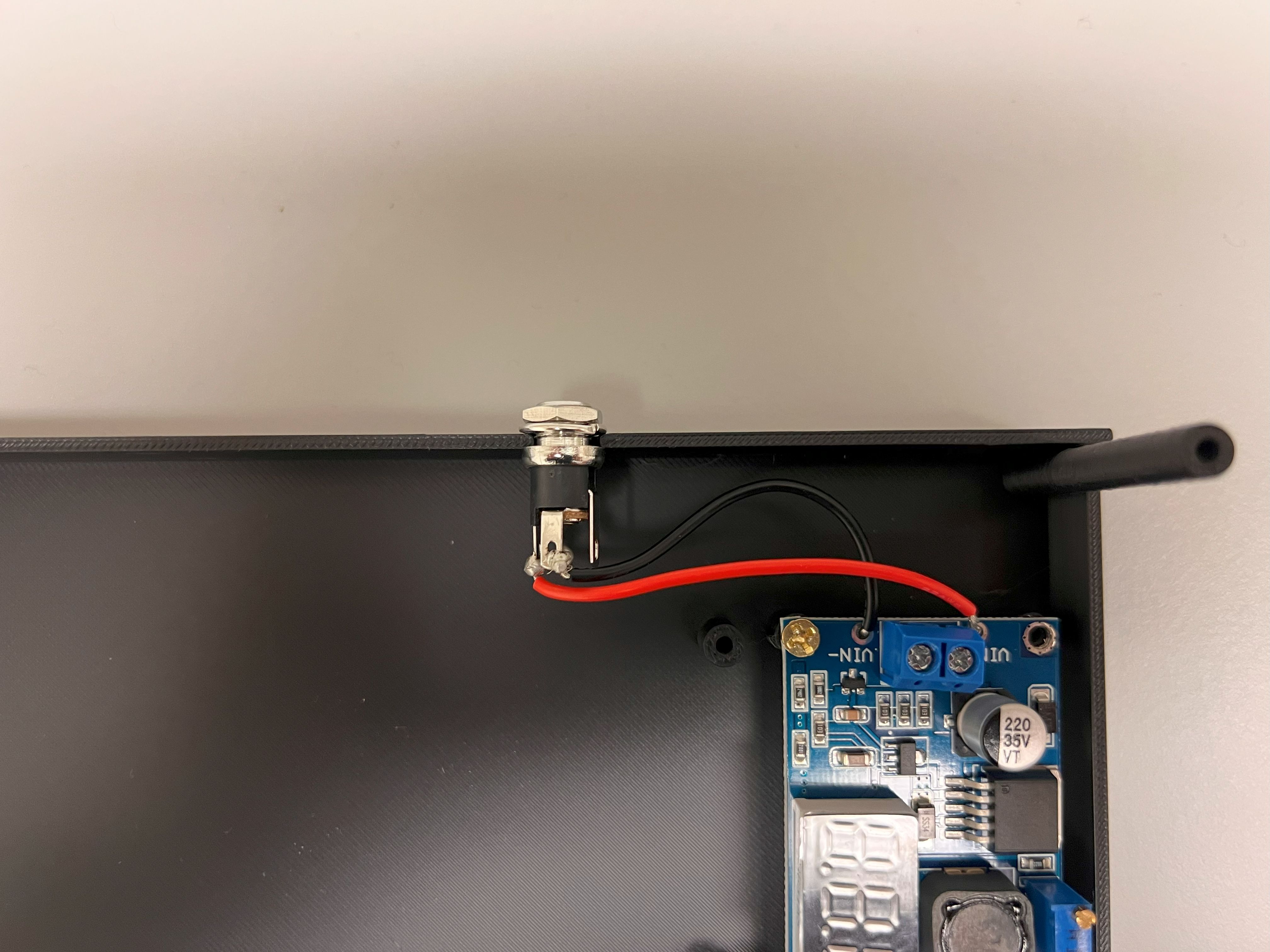
- We could have used a separate 5V Power supply to power the 8-Channel Relay. But we will be using a DC-DC Buck Converter to Step Down the 24V DC to 5V DC for the 8-Channel Relay instead. This way we can use a Single Power Source for all the Components.
- You can watch this Youtube Video to learn how it works.
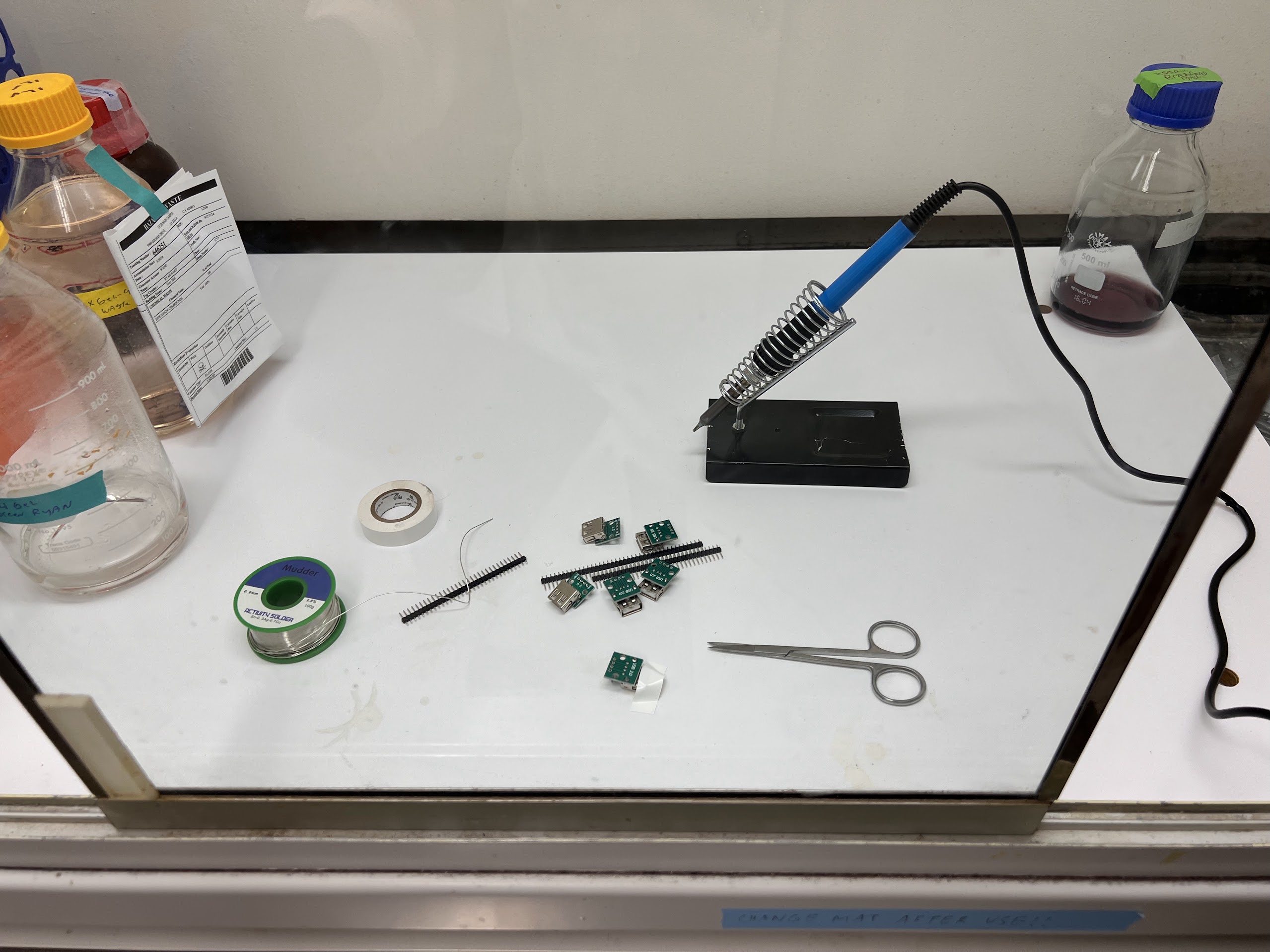
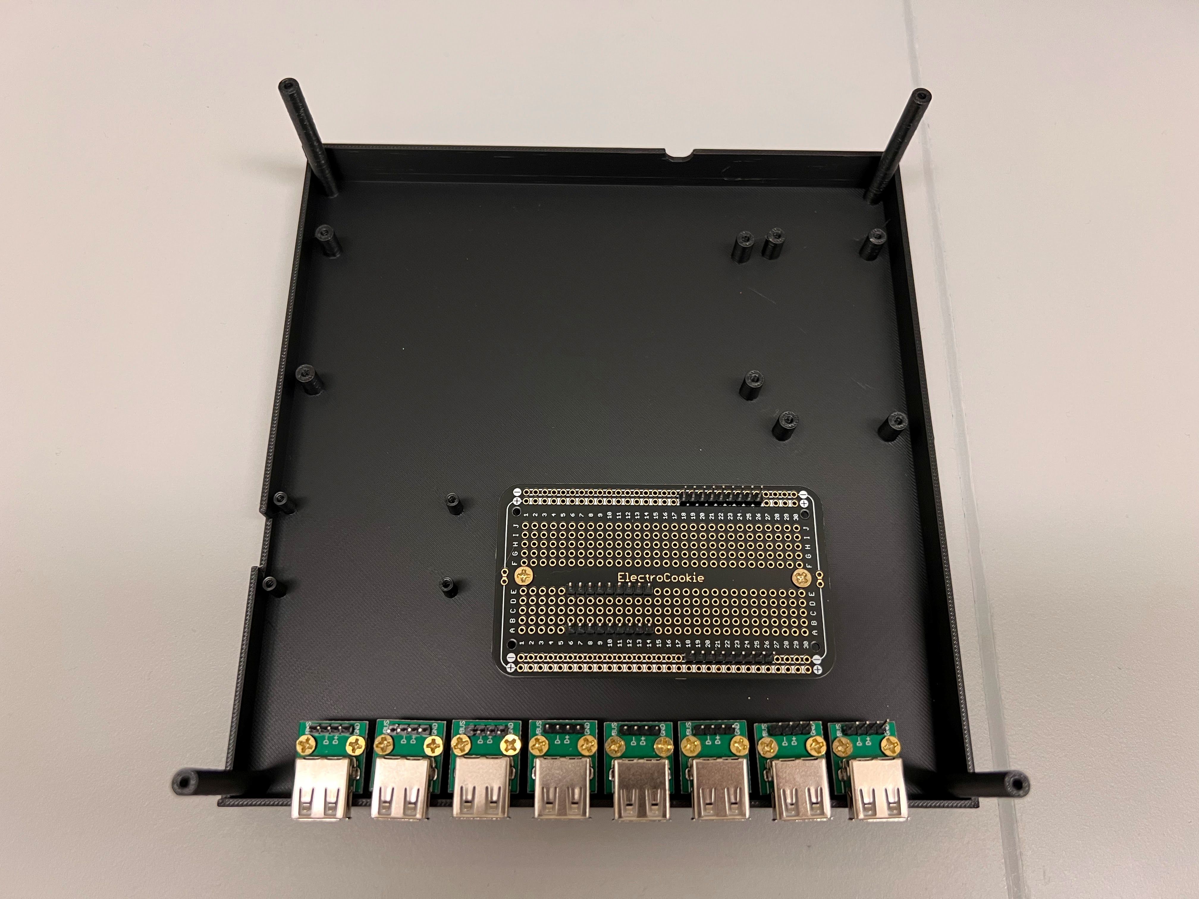
3D Printing Valve Controller Housing
- We used a Bambu Lab X1 Carbon to print the Housing.
- 0.4mm Nozzle
- Textured PEI Plate
- We generated a 3MF File with all the Settings we used for the Print. You can open this file on the Orca Slicer.
- The Original STEP Files and F3D Files can be found in this directory.
- We recommend getting a 3D Printing Accessories Kit if you haven't purchased one already.
- Its extremely helpful in removing supports and cleaning up the print.
- You can watch the Timelapse Videos Below: