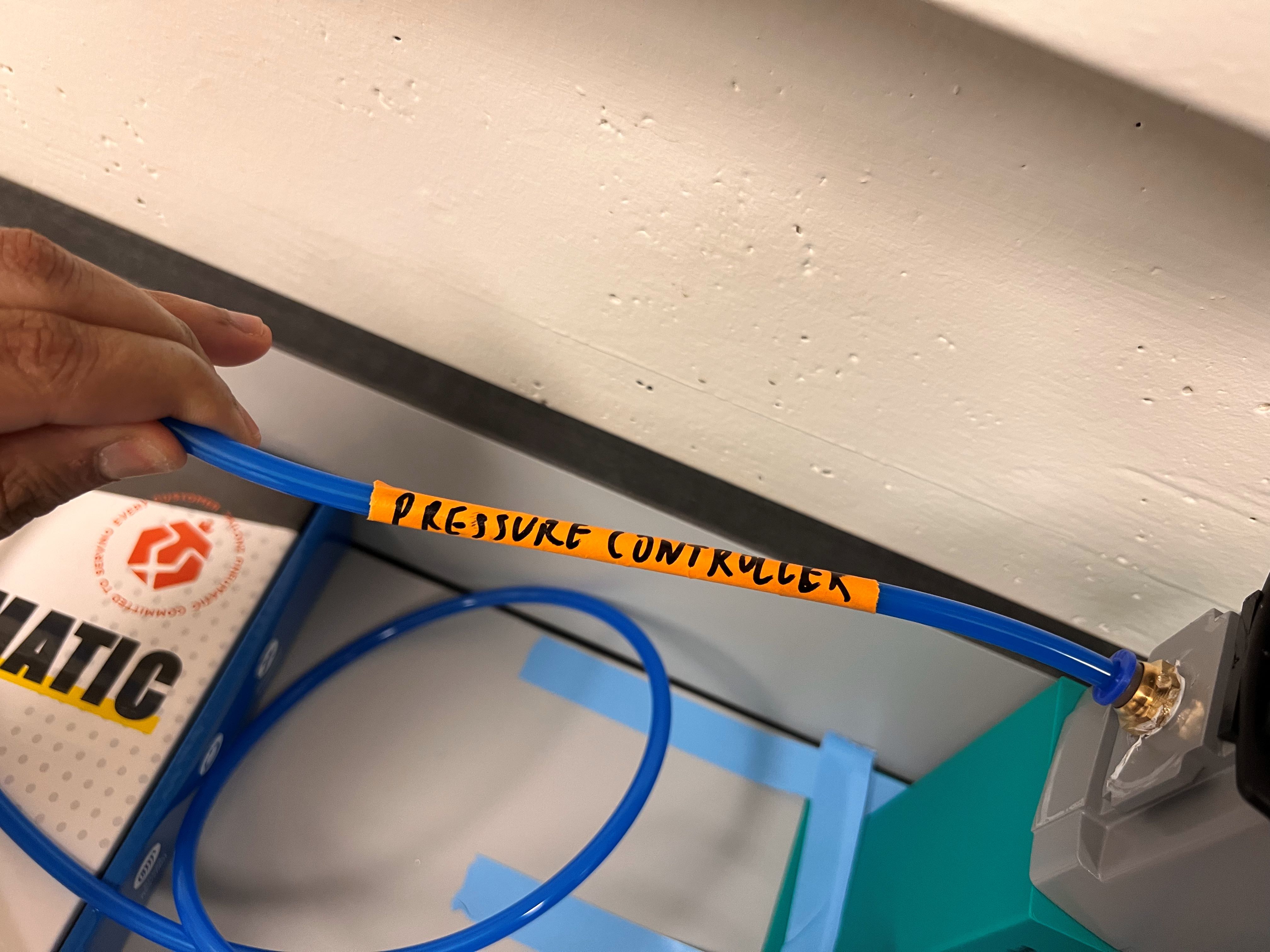
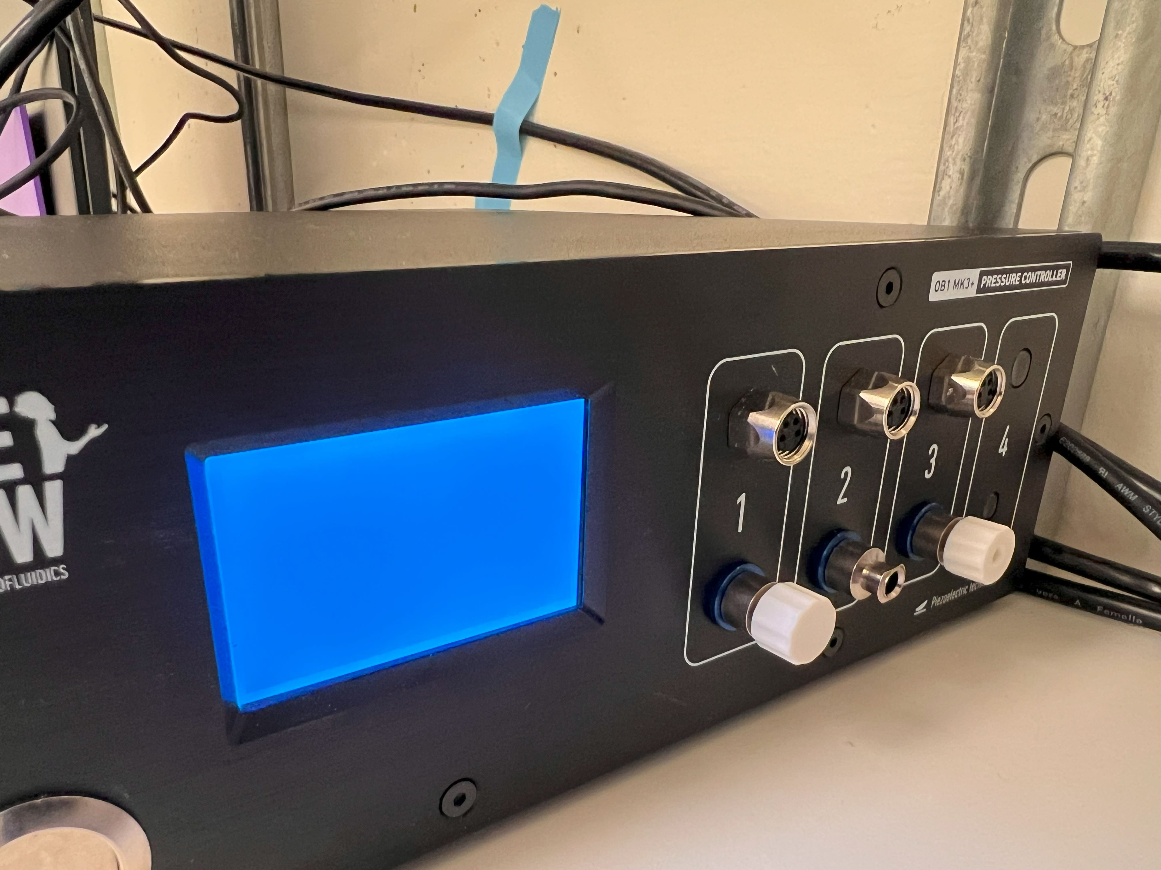
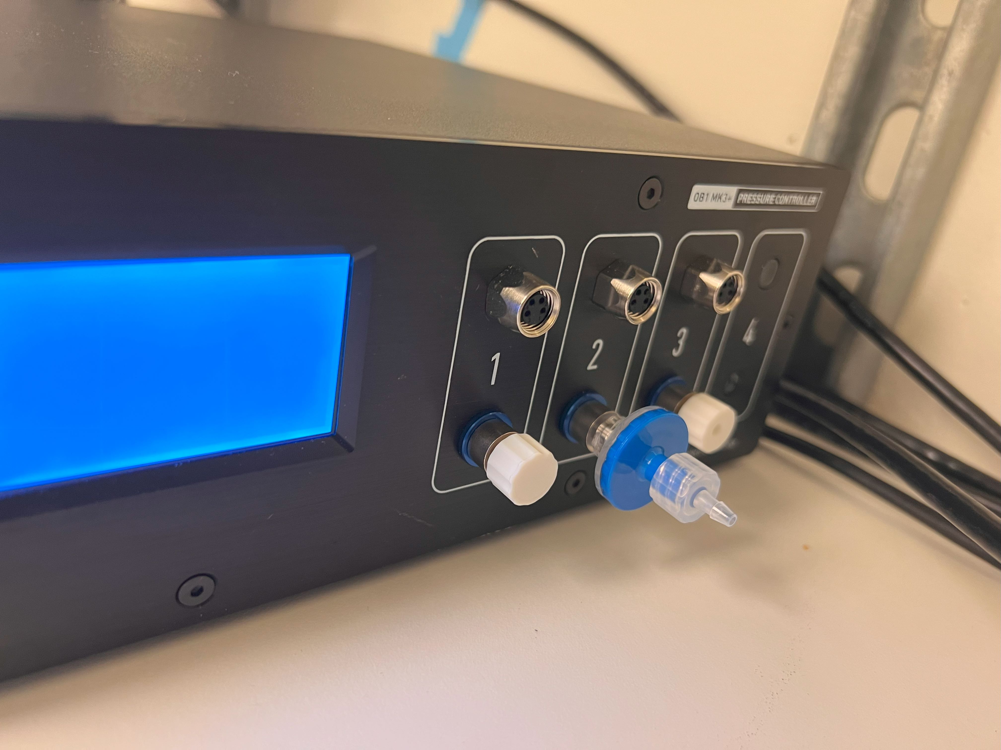
Pressure Controller Connection Started
Pressure Controller ID: 0
True
{'baudrate': 9600, 'bytesize': 8, 'parity': 'N', 'stopbits': 1, 'xonxoff': False, 'dsrdtr': False, 'rtscts': False, 'timeout': 1, 'write_timeout': 0, 'inter_byte_timeout': None}
True
{'baudrate': 9600, 'bytesize': 8, 'parity': 'N', 'stopbits': 1, 'xonxoff': False, 'dsrdtr': False, 'rtscts': False, 'timeout': 1, 'write_timeout': 0, 'inter_byte_timeout': None}
True
{'baudrate': 9600, 'bytesize': 8, 'parity': 'N', 'stopbits': 1, 'xonxoff': False, 'dsrdtr': False, 'rtscts': False, 'timeout': 1, 'write_timeout': 0, 'inter_byte_timeout': None}
COM12
{'baudrate': 9600, 'bytesize': 8, 'parity': 'N', 'stopbits': 1, 'xonxoff': False, 'dsrdtr': False, 'rtscts': False, 'timeout': 1, 'write_timeout': 0, 'inter_byte_timeout': None}
True
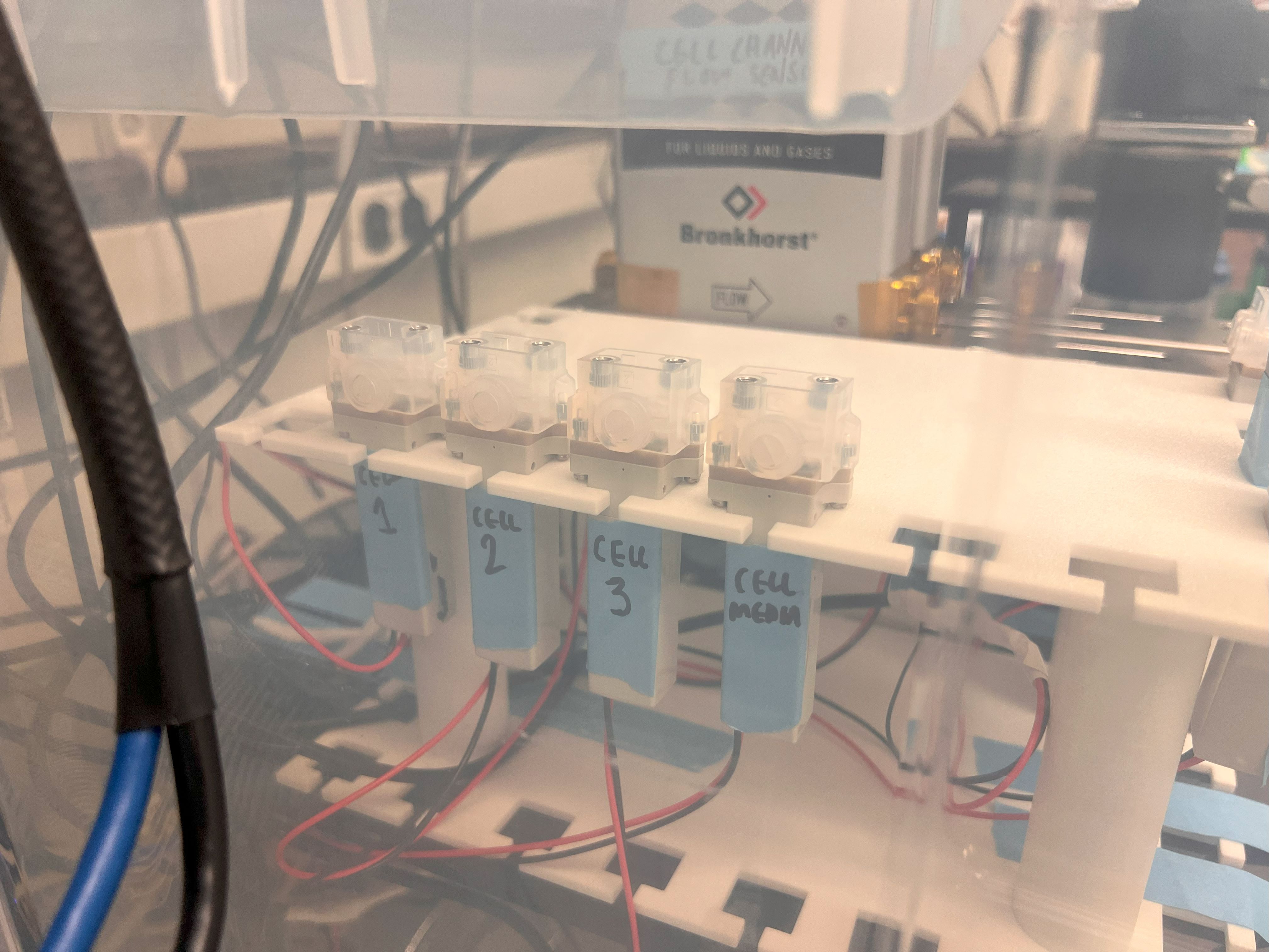
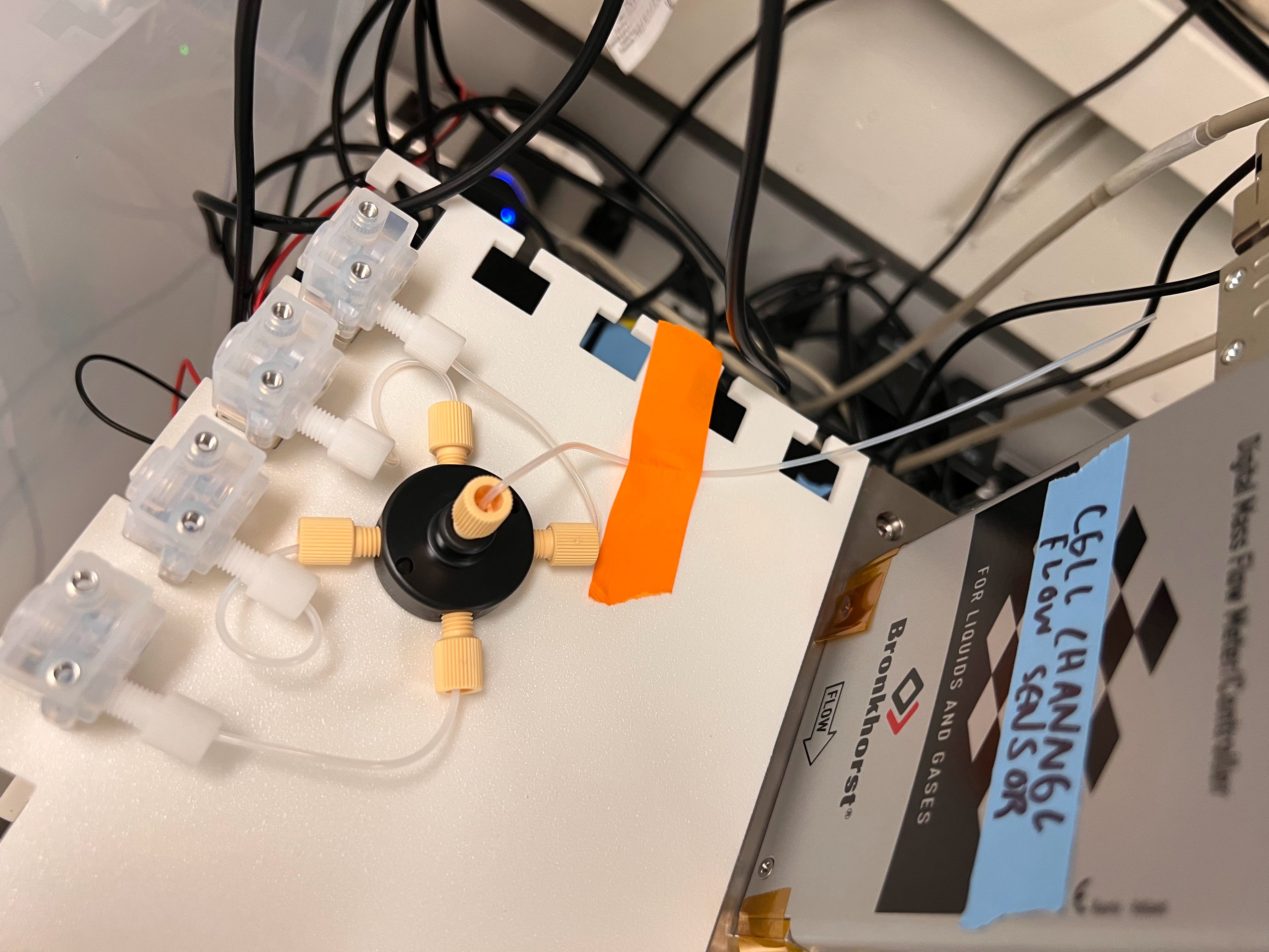
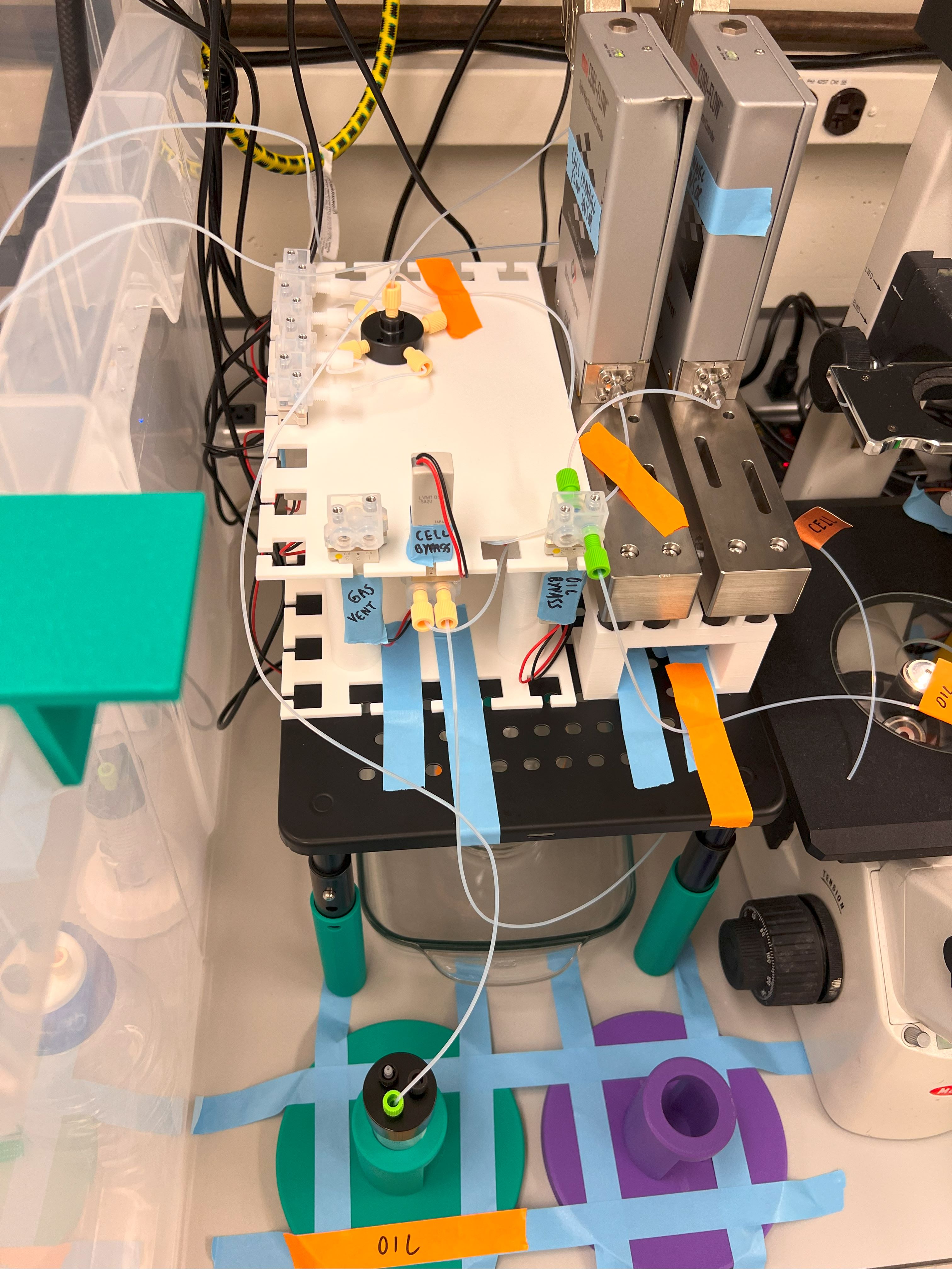
Cell Channel Flow Meter ID: 3000
error 0 :
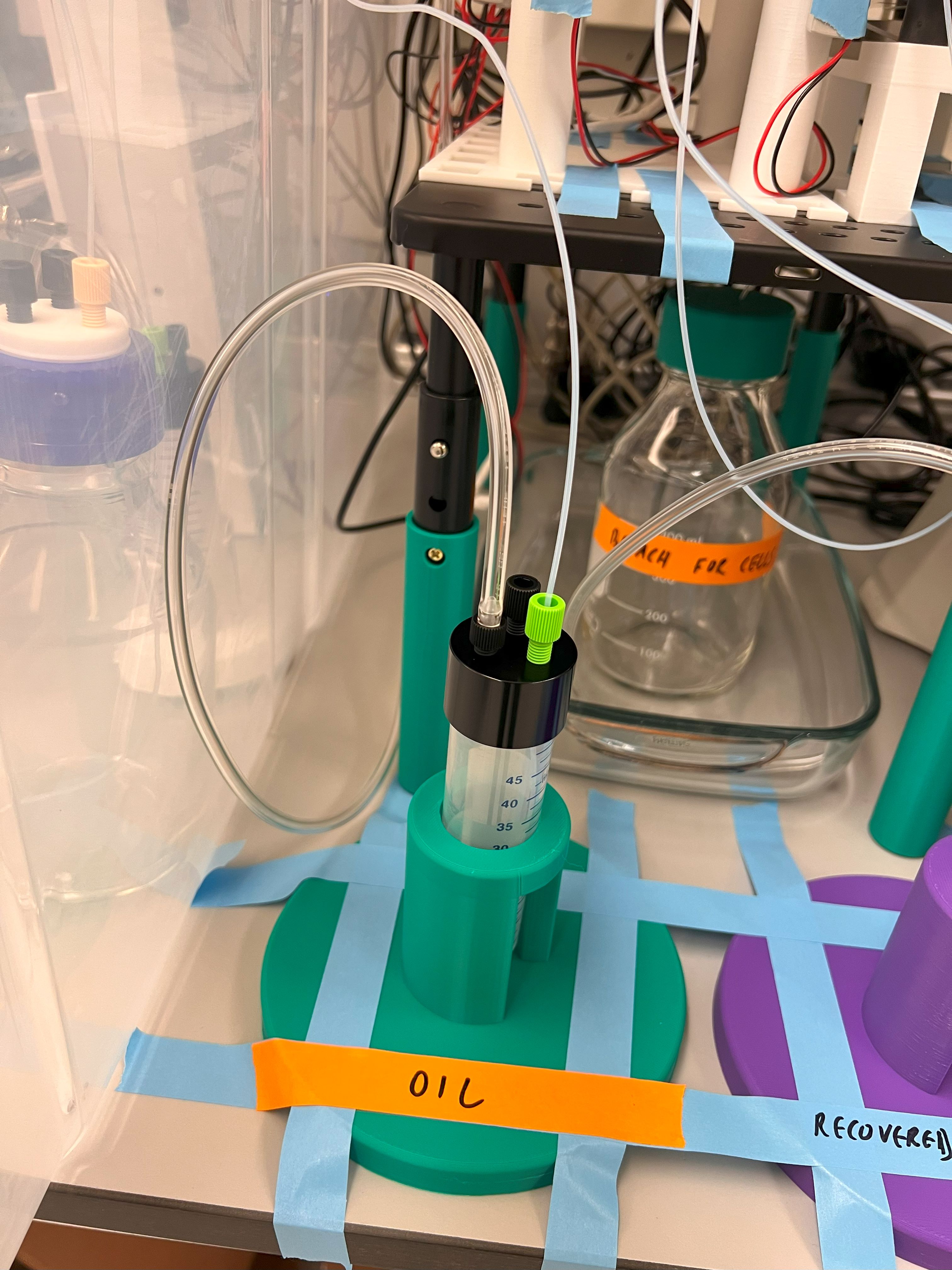
Oil Channel Flow Meter ID: 3001
error 0 :
Cell Channel Density:
1.2680259943008423
Cell Channel Flow rate:
-1103.77129063566
Oil Channel Density:
2.1396427154541016
Oil Channel Flow rate:
-1381.2710424672853
COM15
{'baudrate': 9600, 'bytesize': 8, 'parity': 'N', 'stopbits': 1, 'xonxoff': False, 'dsrdtr': False, 'rtscts': False, 'timeout': 1, 'write_timeout': 1, 'inter_byte_timeout': None}
True
COM9
{'baudrate': 9600, 'bytesize': 8, 'parity': 'N', 'stopbits': 1, 'xonxoff': False, 'dsrdtr': False, 'rtscts': False, 'timeout': 1, 'write_timeout': 1, 'inter_byte_timeout': None}
True
COM7
{'baudrate': 9600, 'bytesize': 8, 'parity': 'N', 'stopbits': 1, 'xonxoff': False, 'dsrdtr': False, 'rtscts': False, 'timeout': 1, 'write_timeout': 1, 'inter_byte_timeout': None}
True
COM10
{'baudrate': 9600, 'bytesize': 8, 'parity': 'N', 'stopbits': 1, 'xonxoff': False, 'dsrdtr': False, 'rtscts': False, 'timeout': 1, 'write_timeout': 0, 'inter_byte_timeout': None}
True
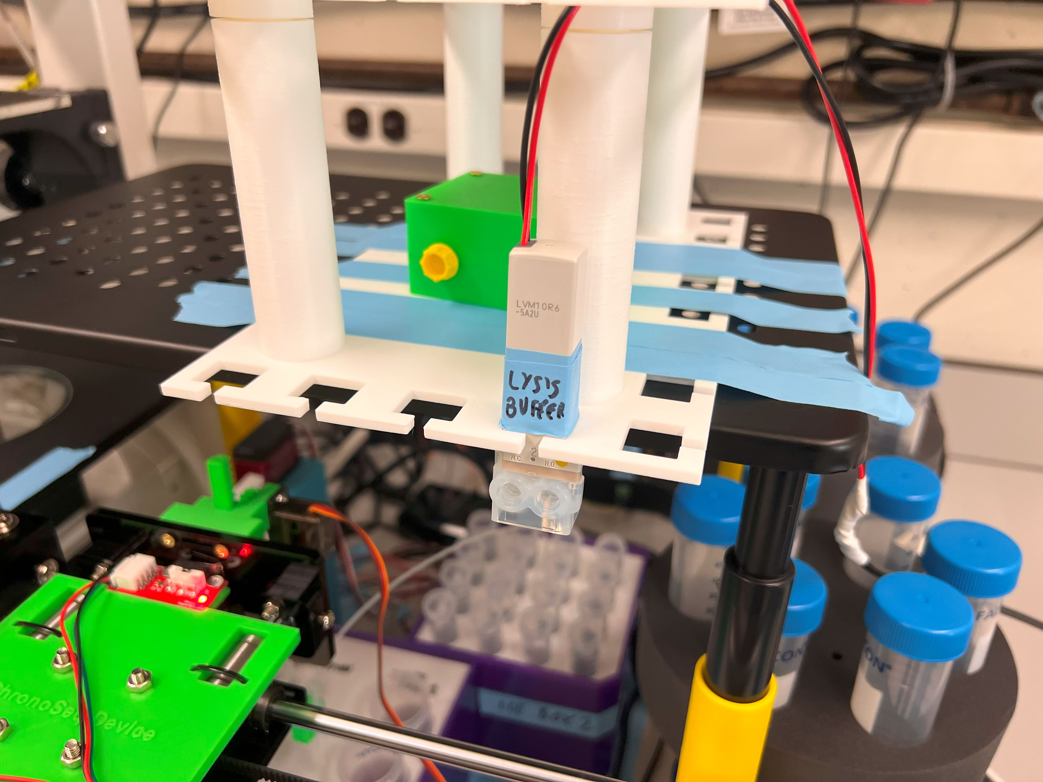
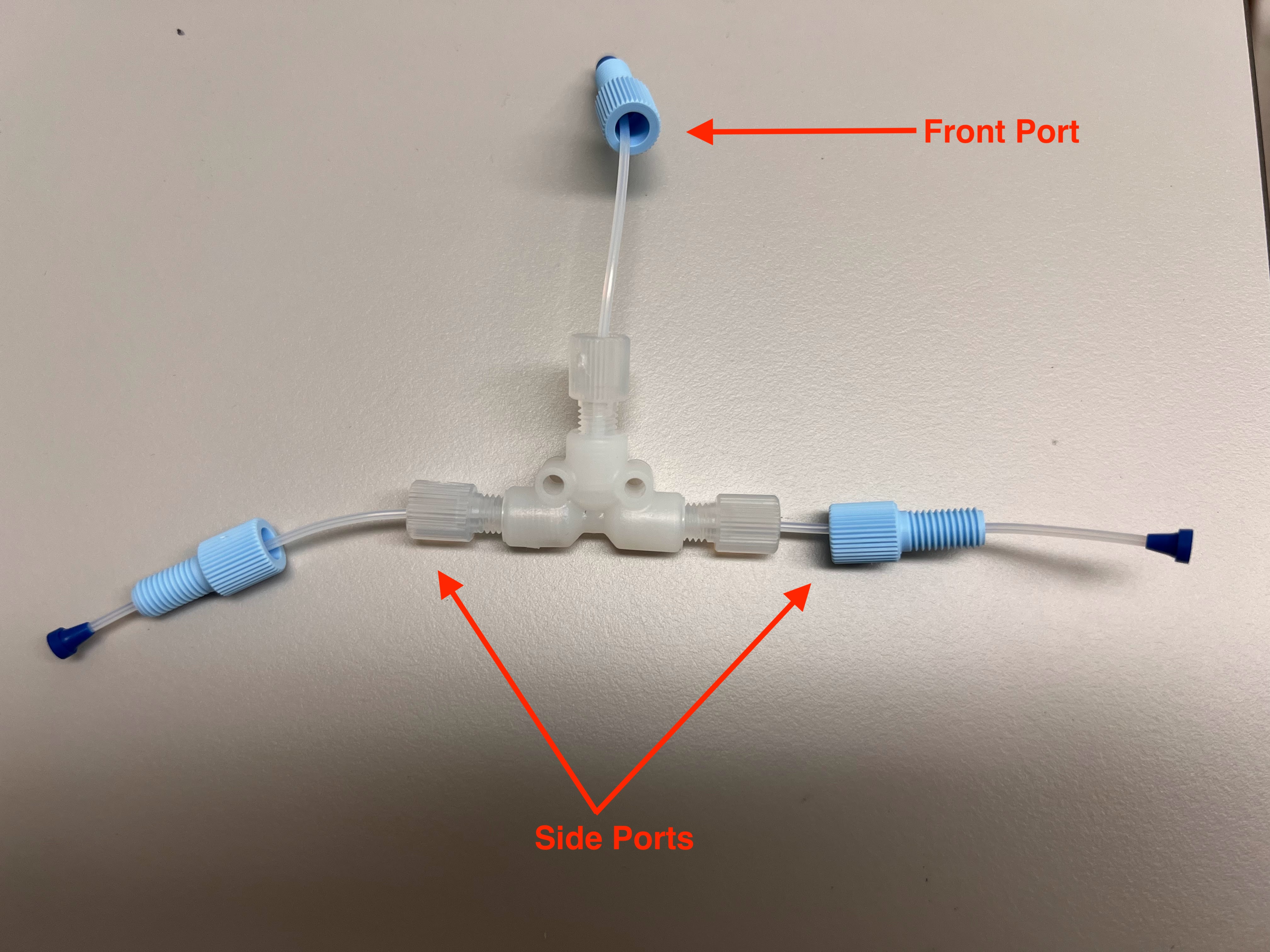
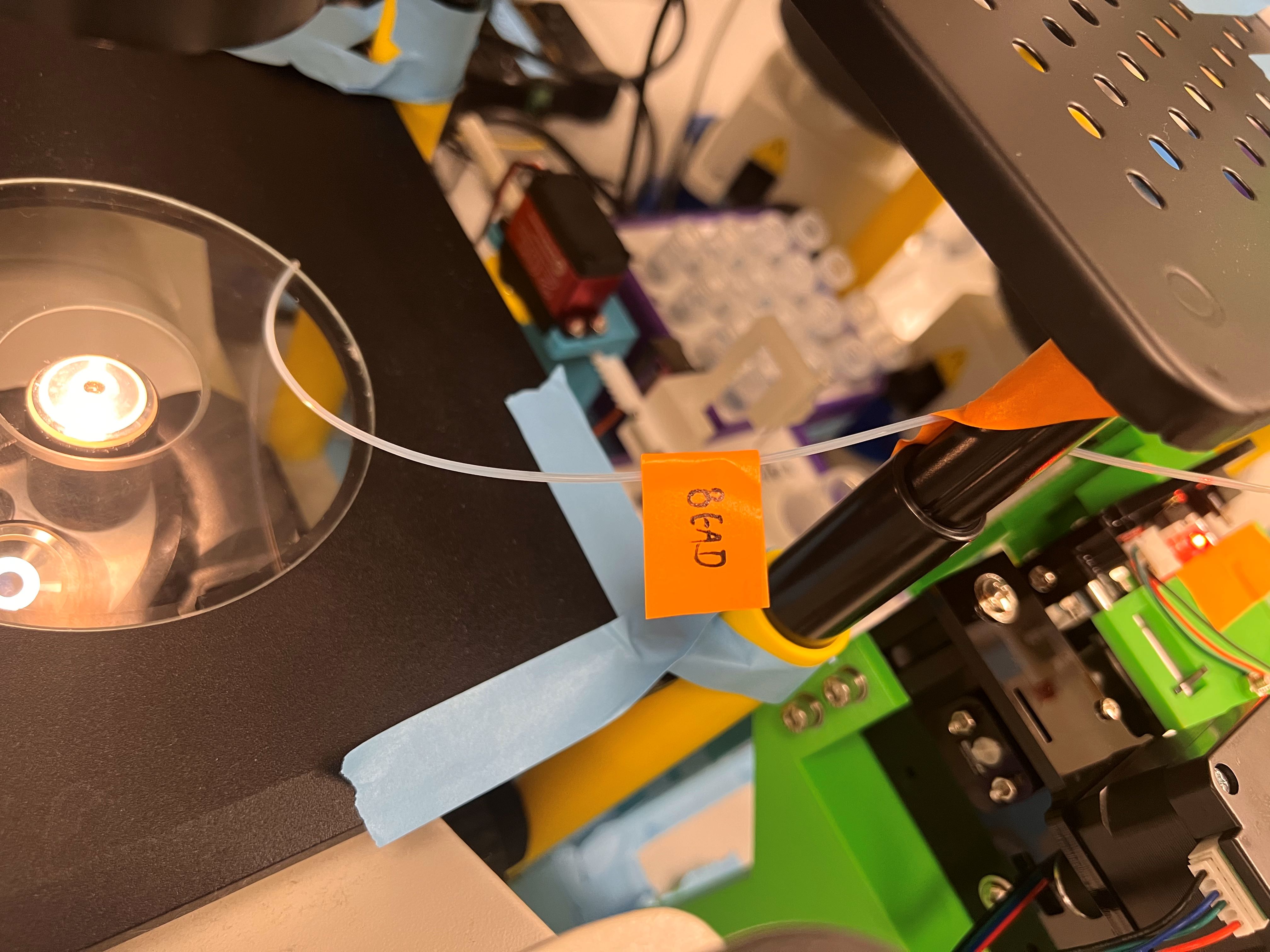
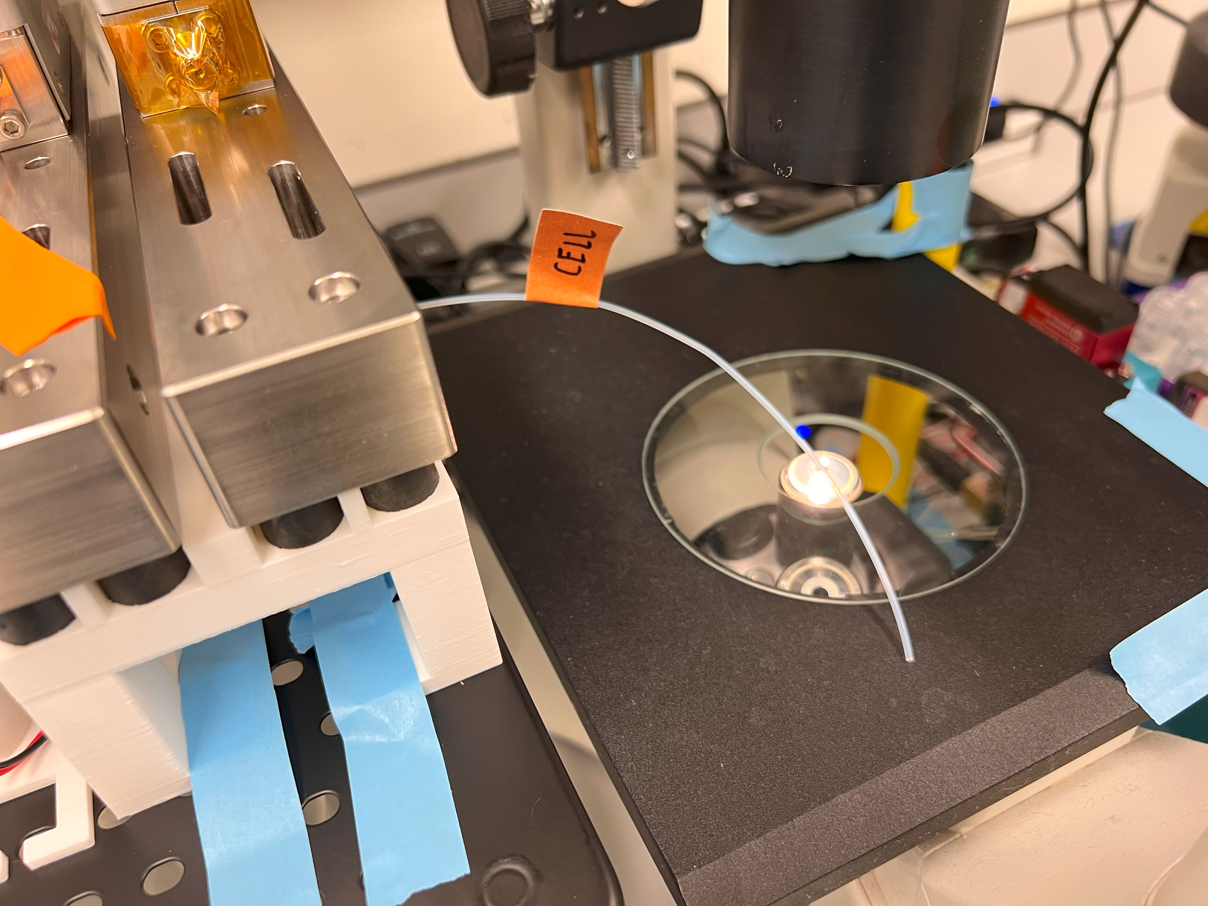
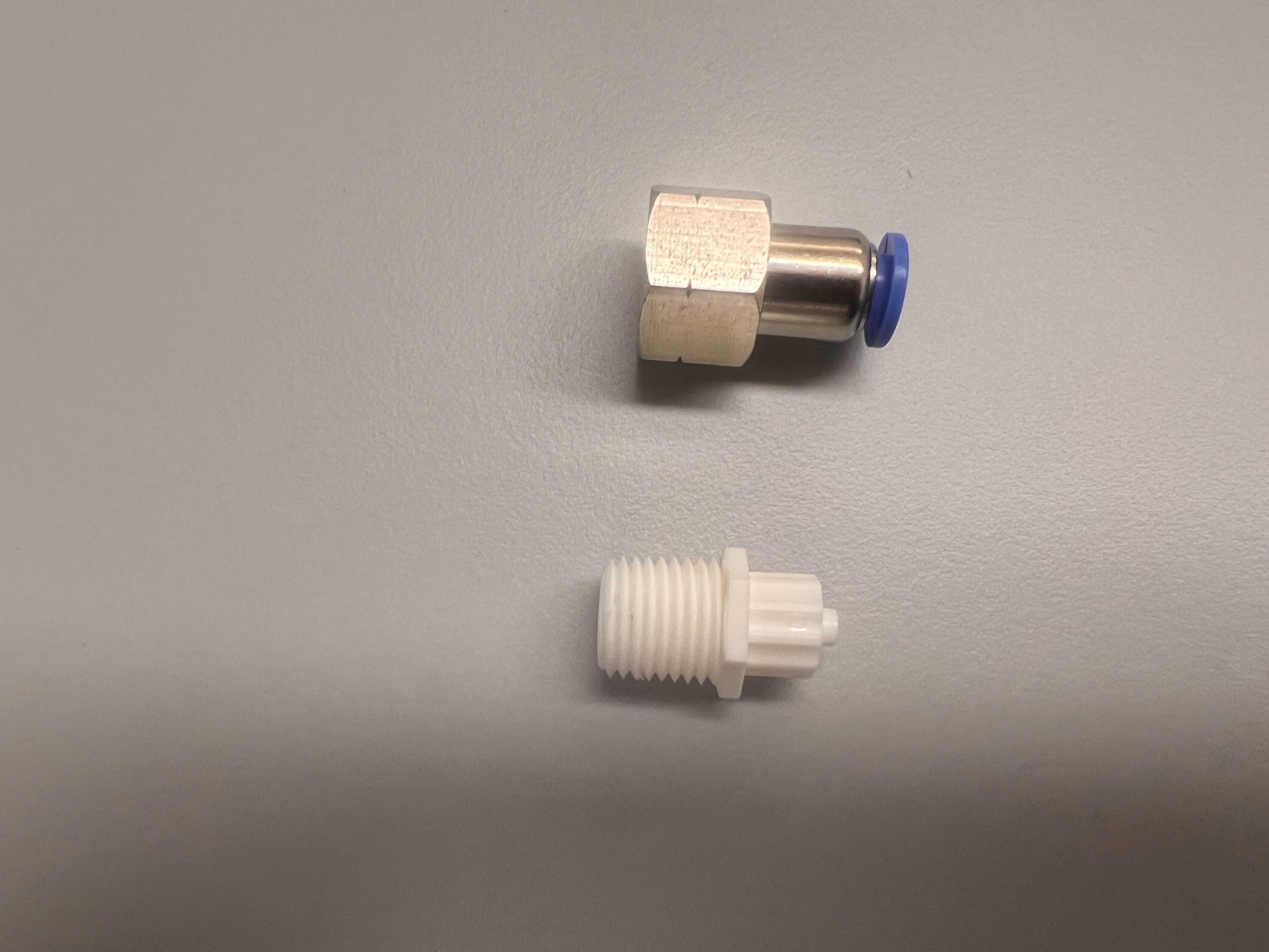
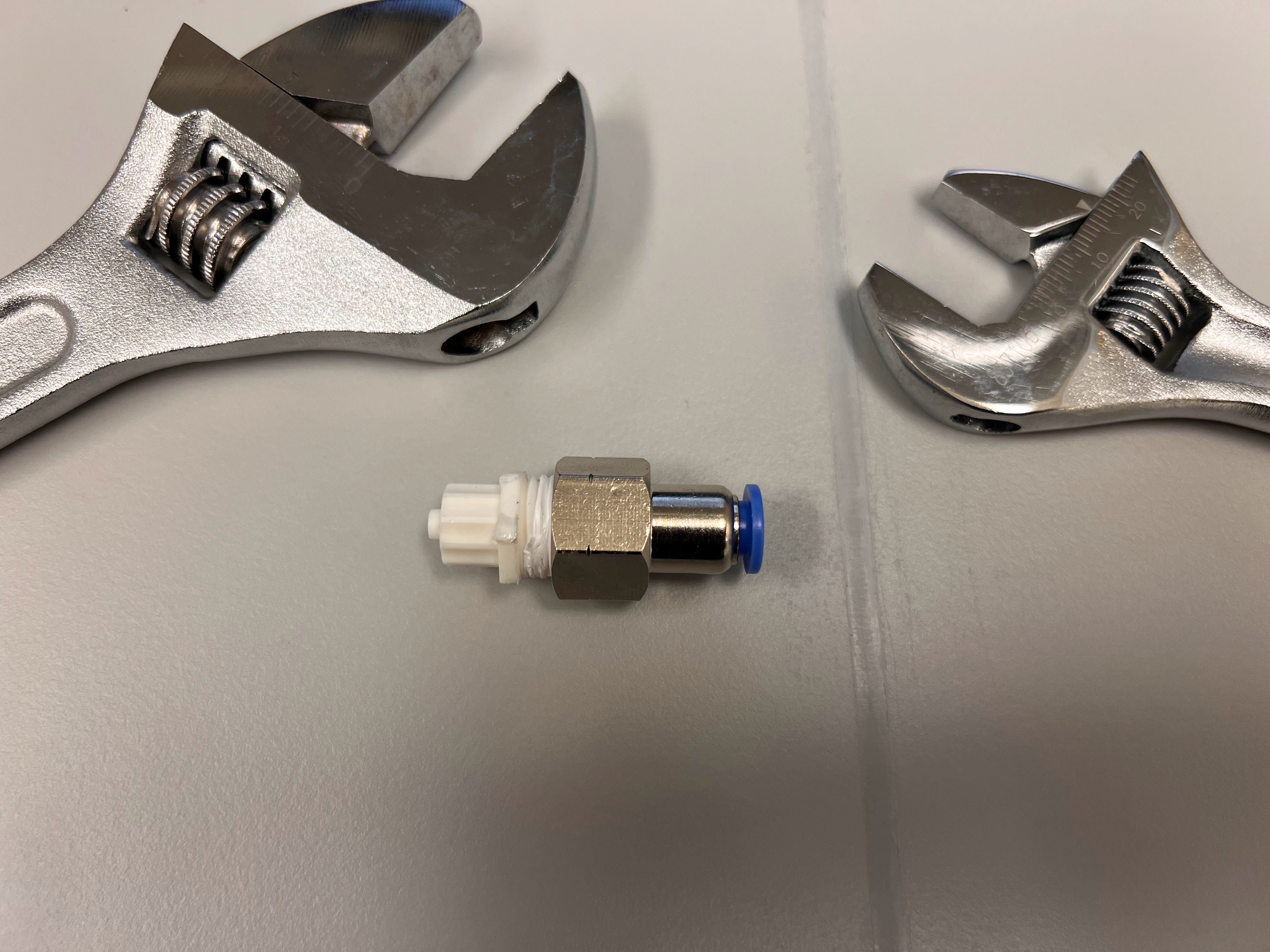
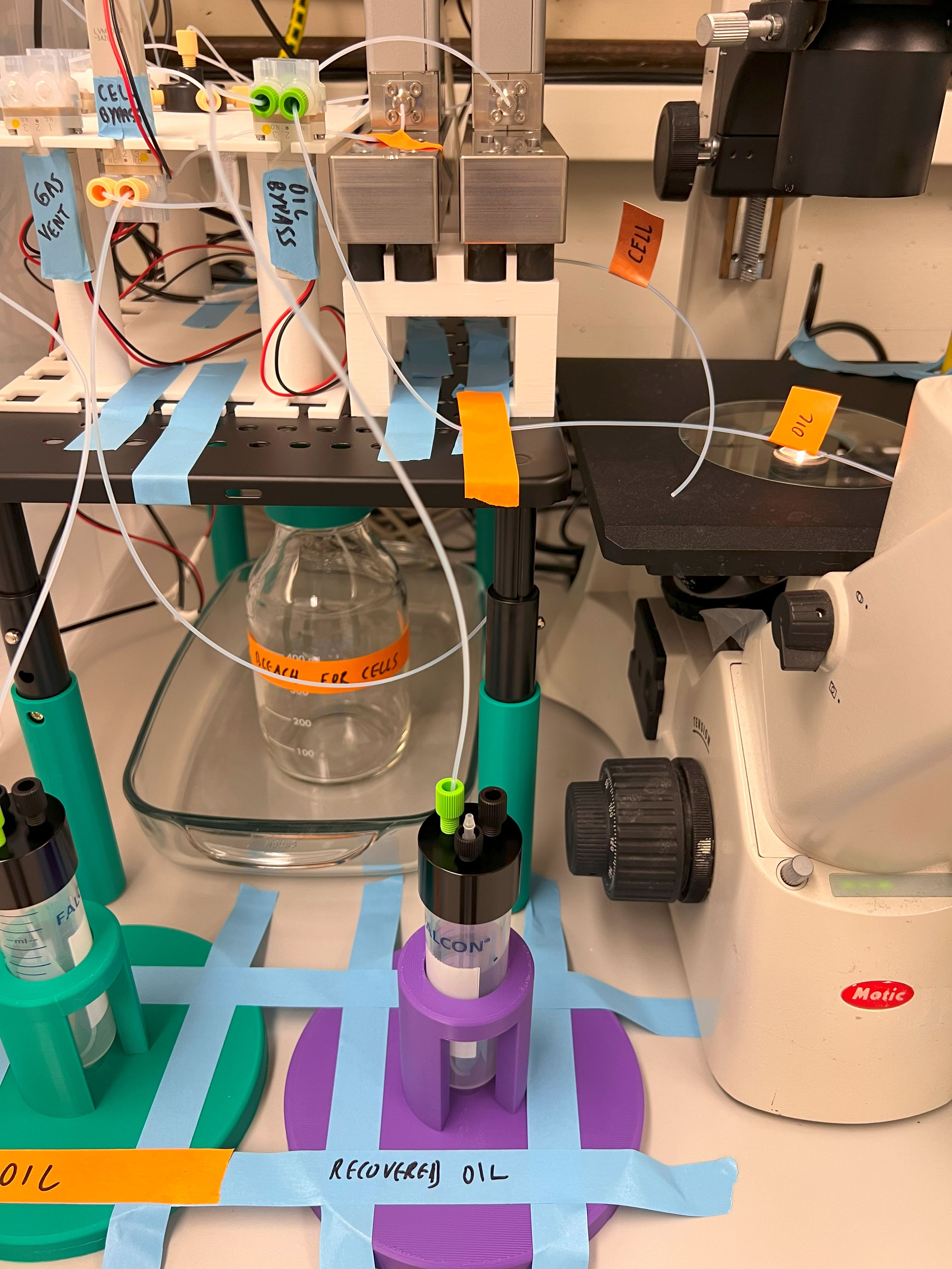
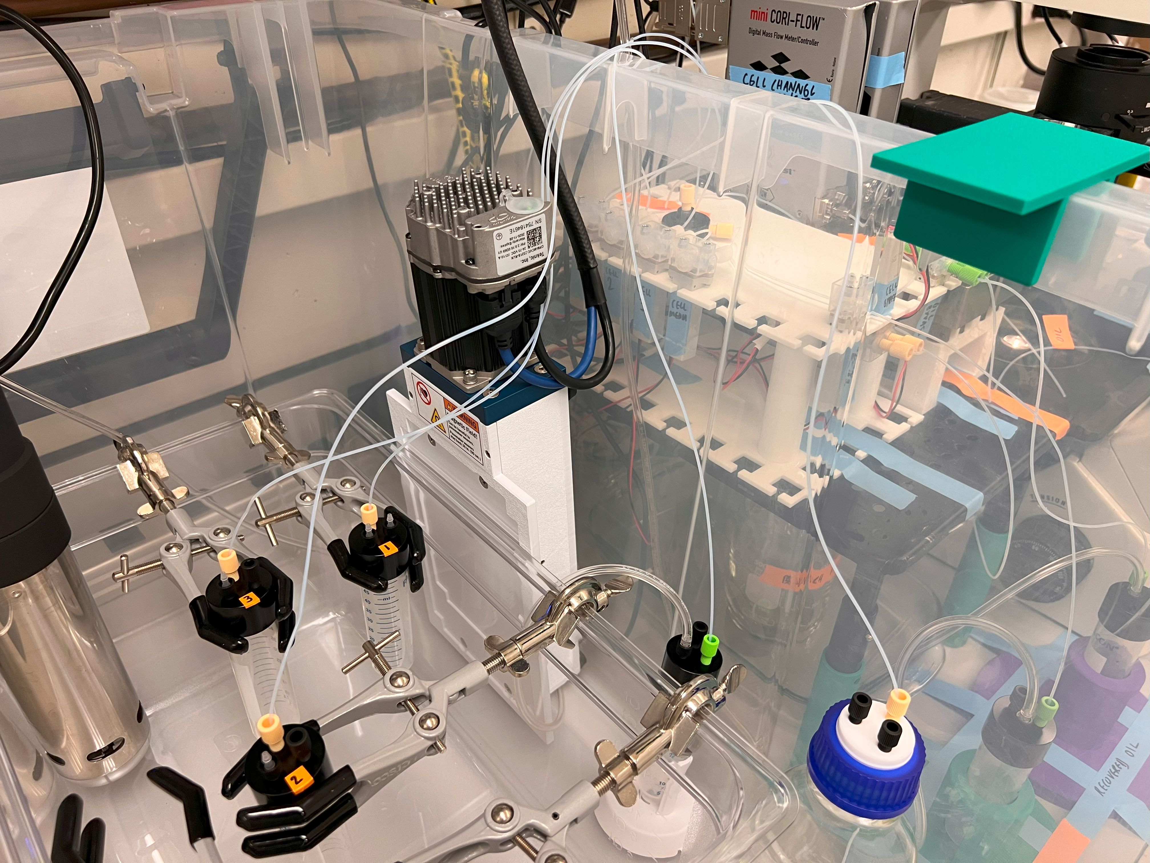

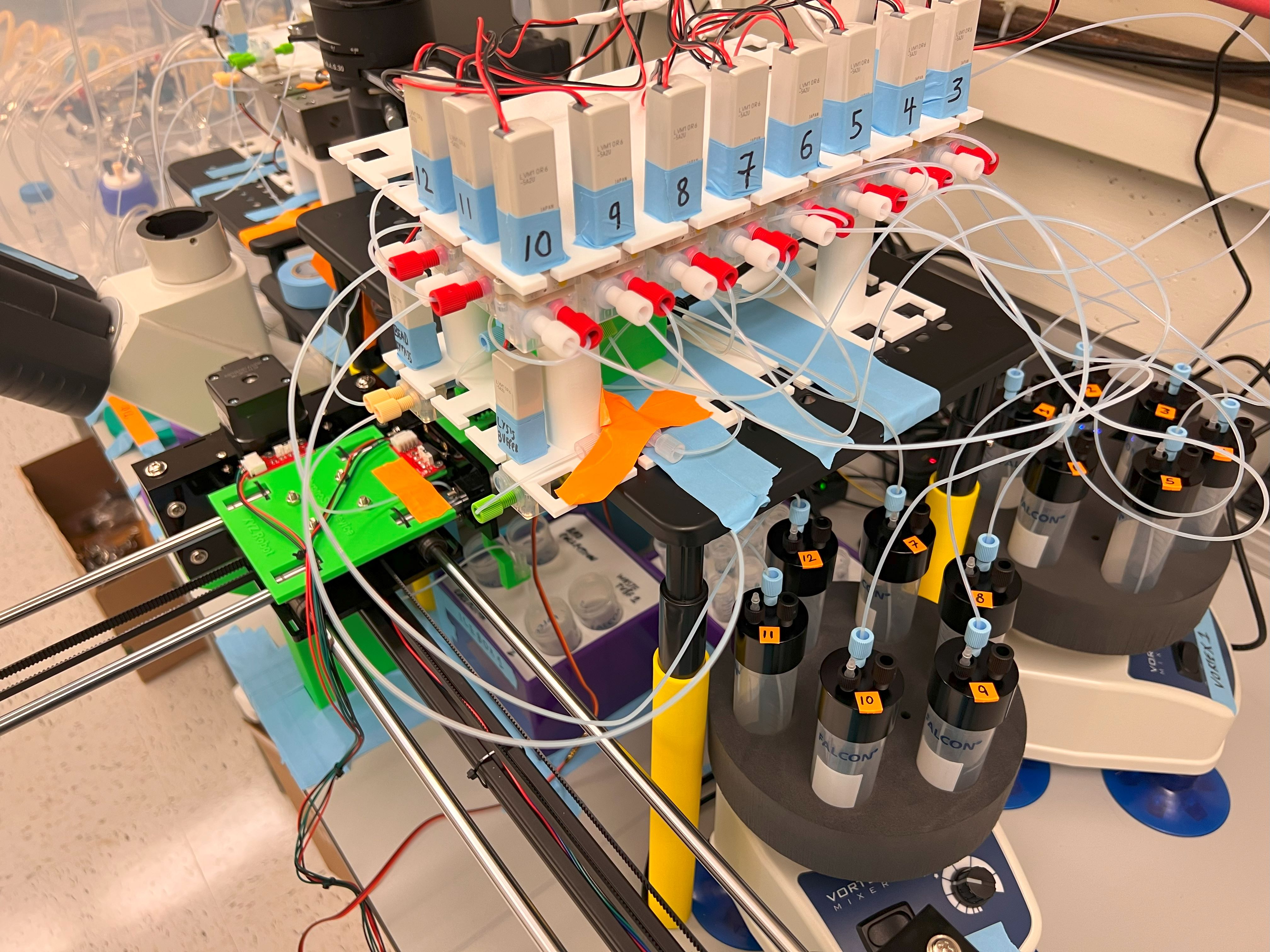
.jpg)
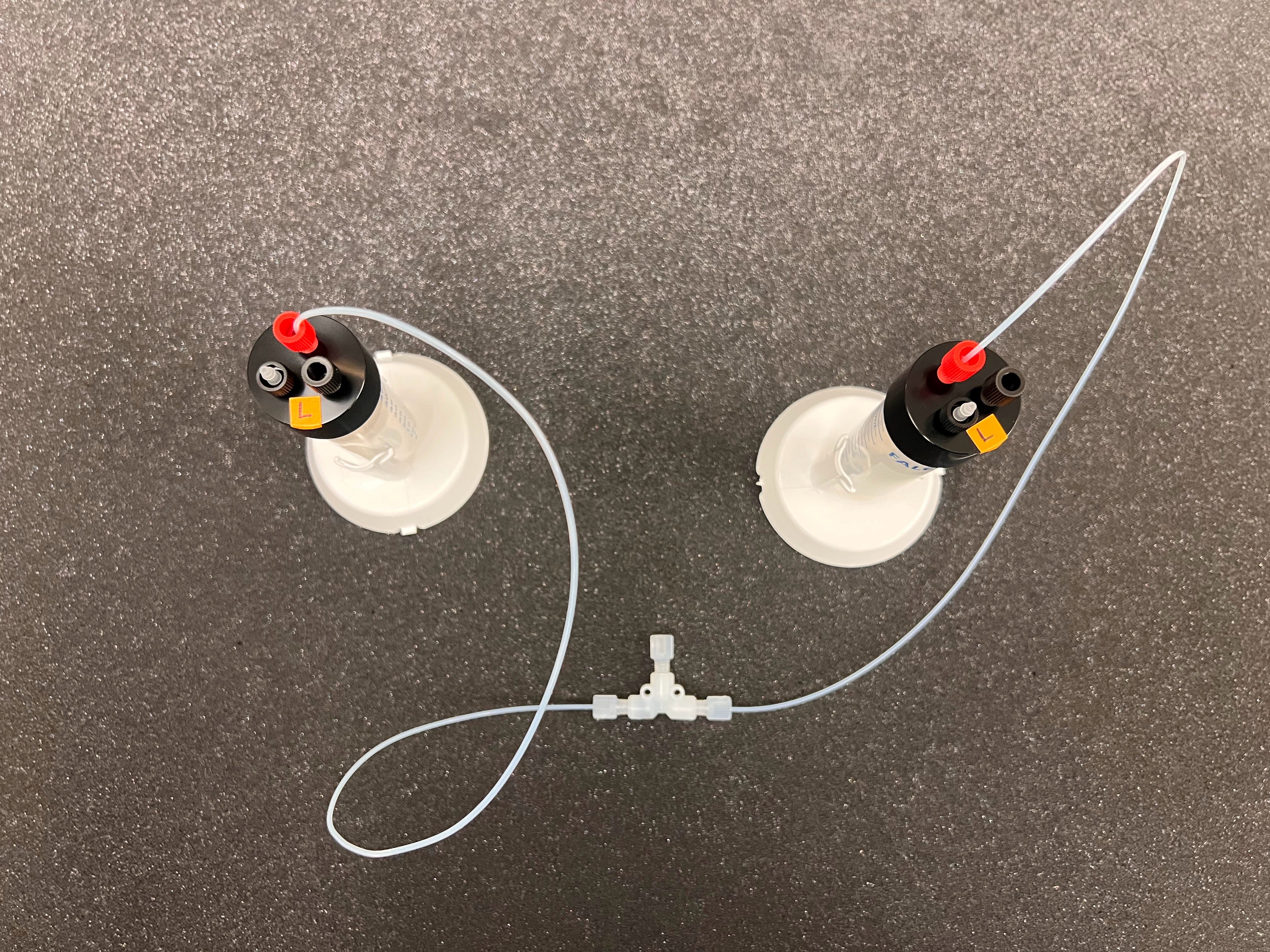
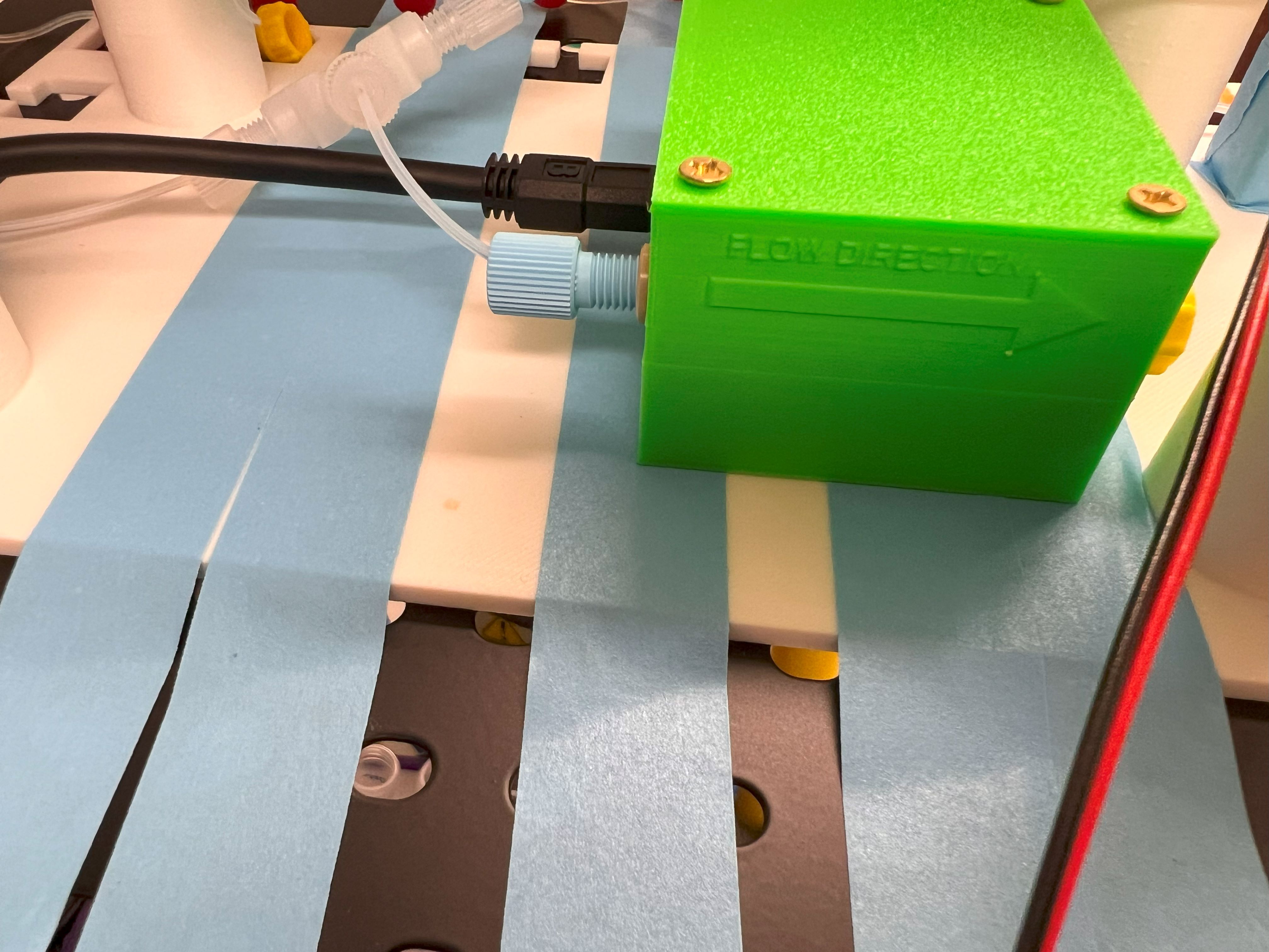
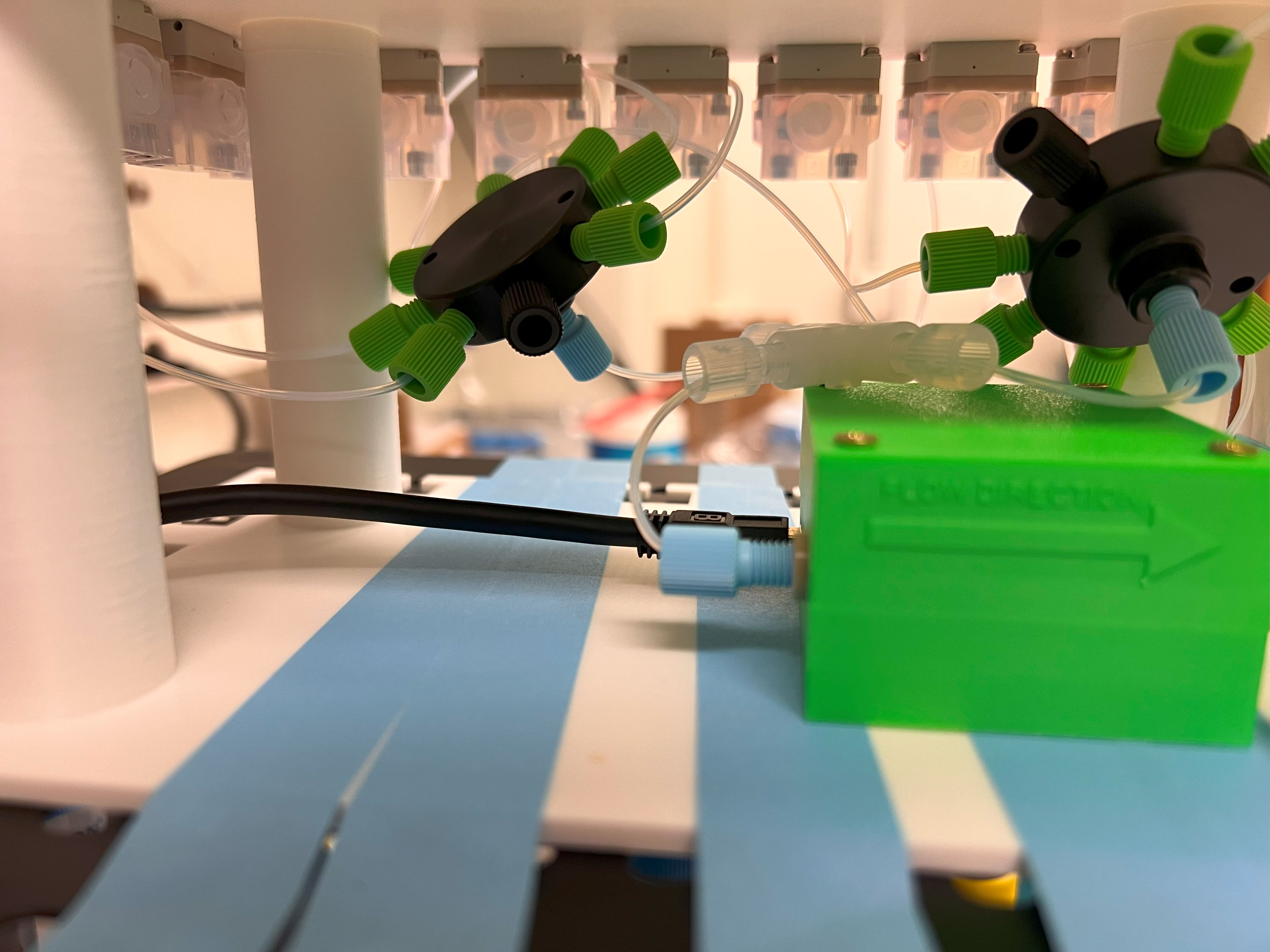
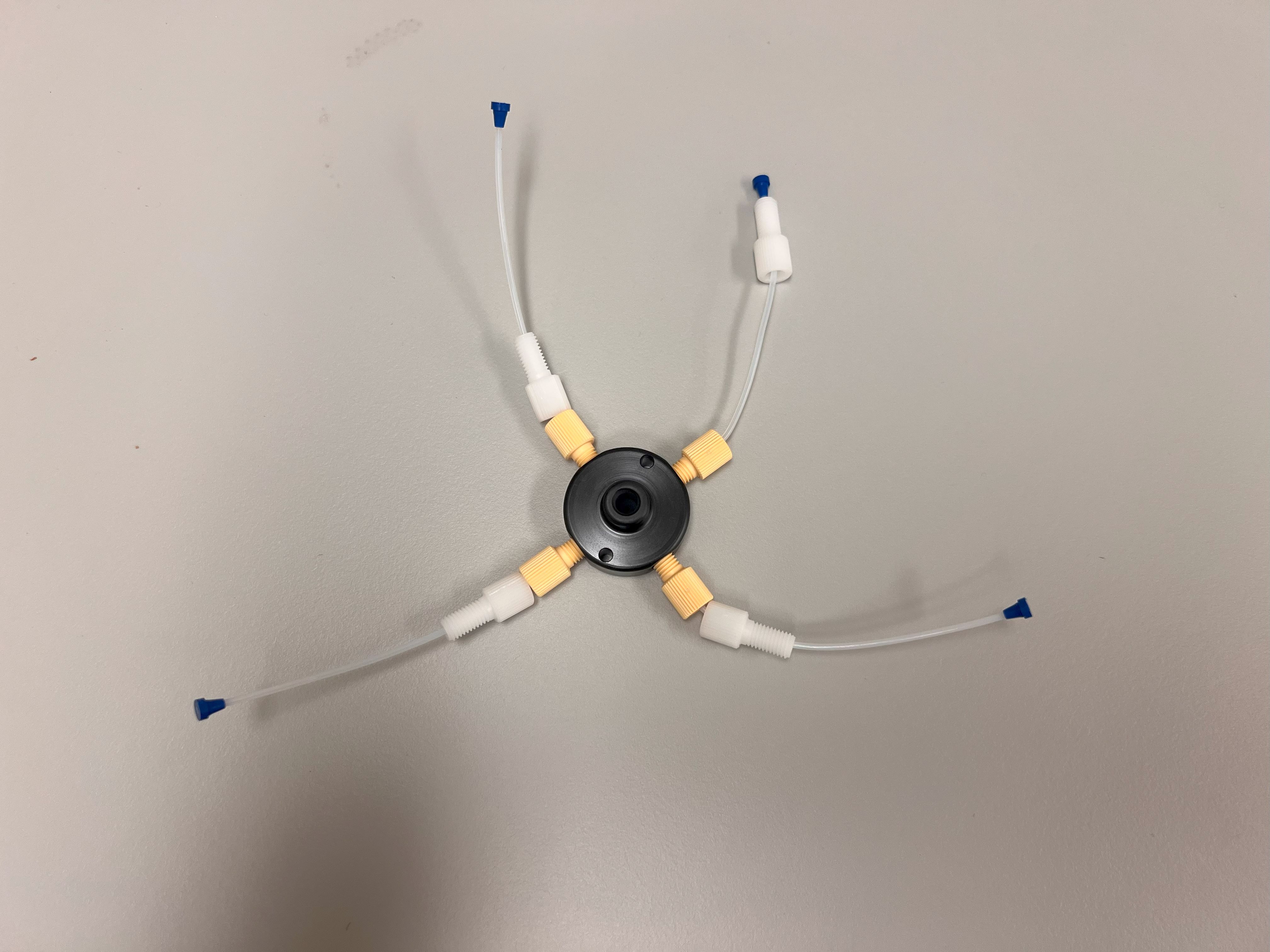
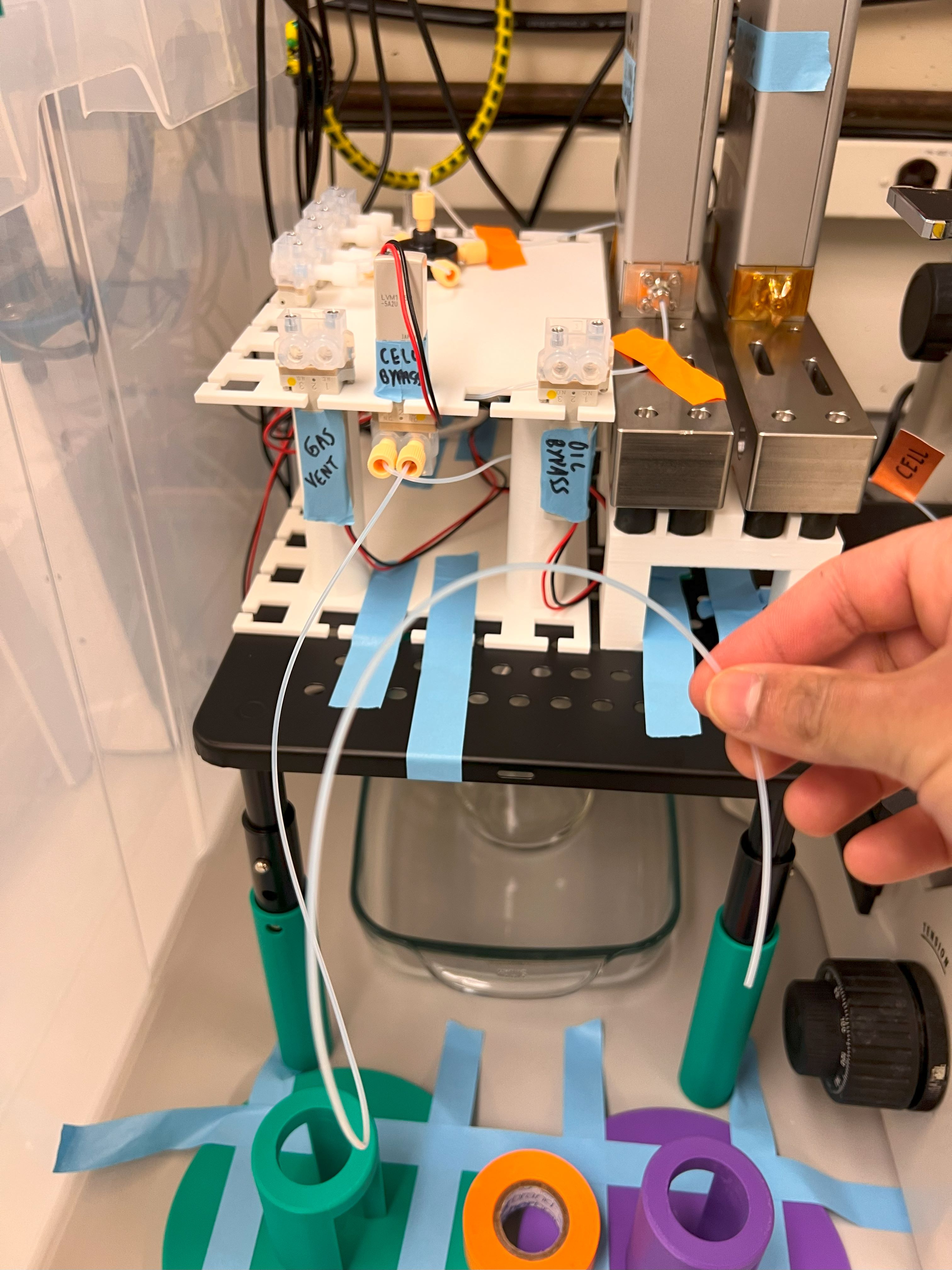
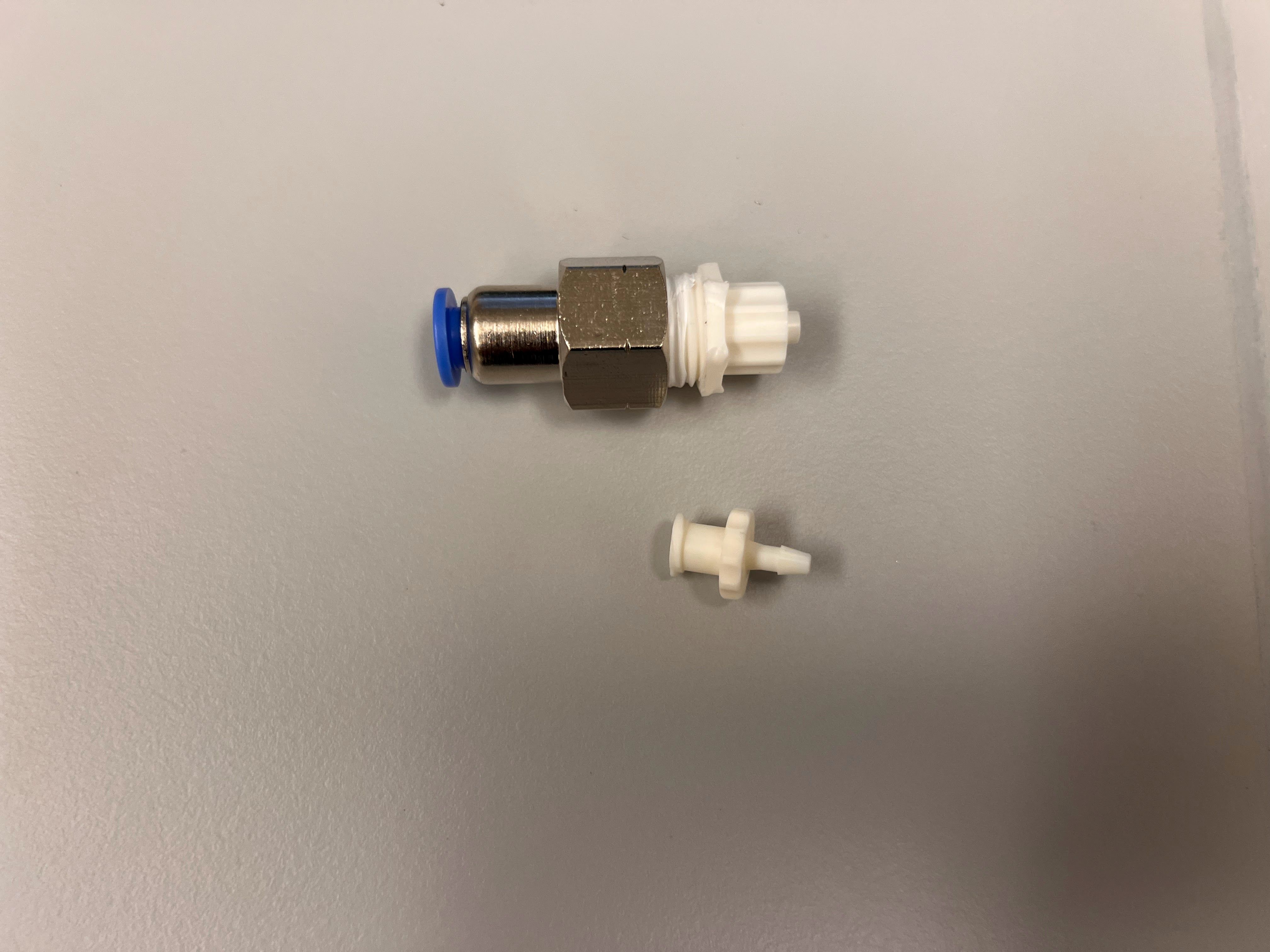
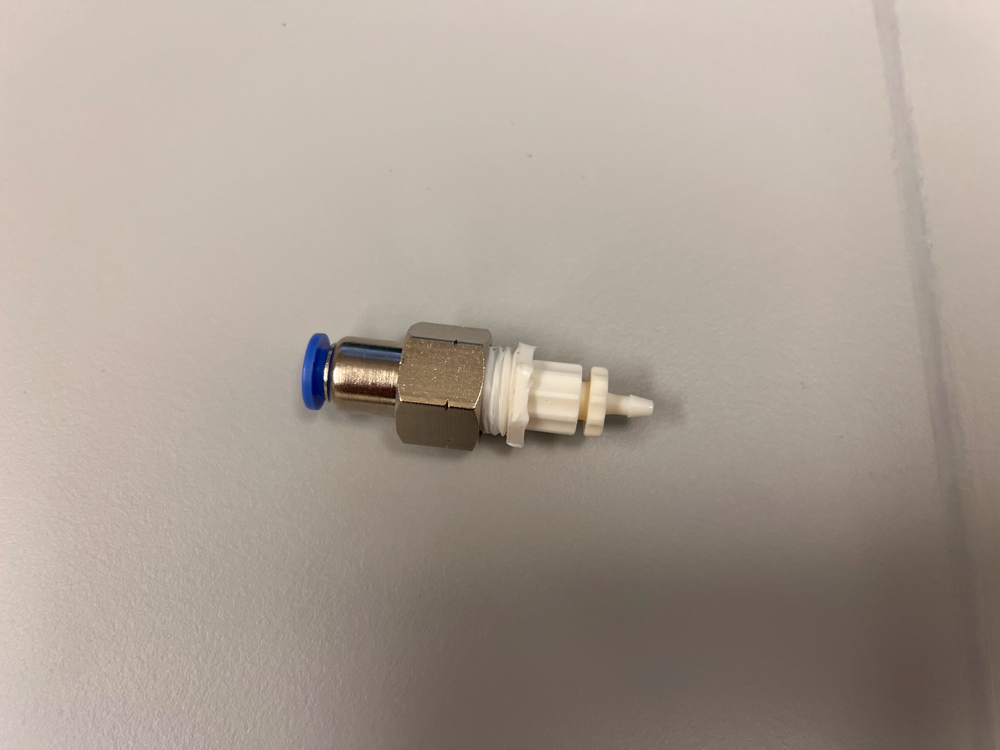
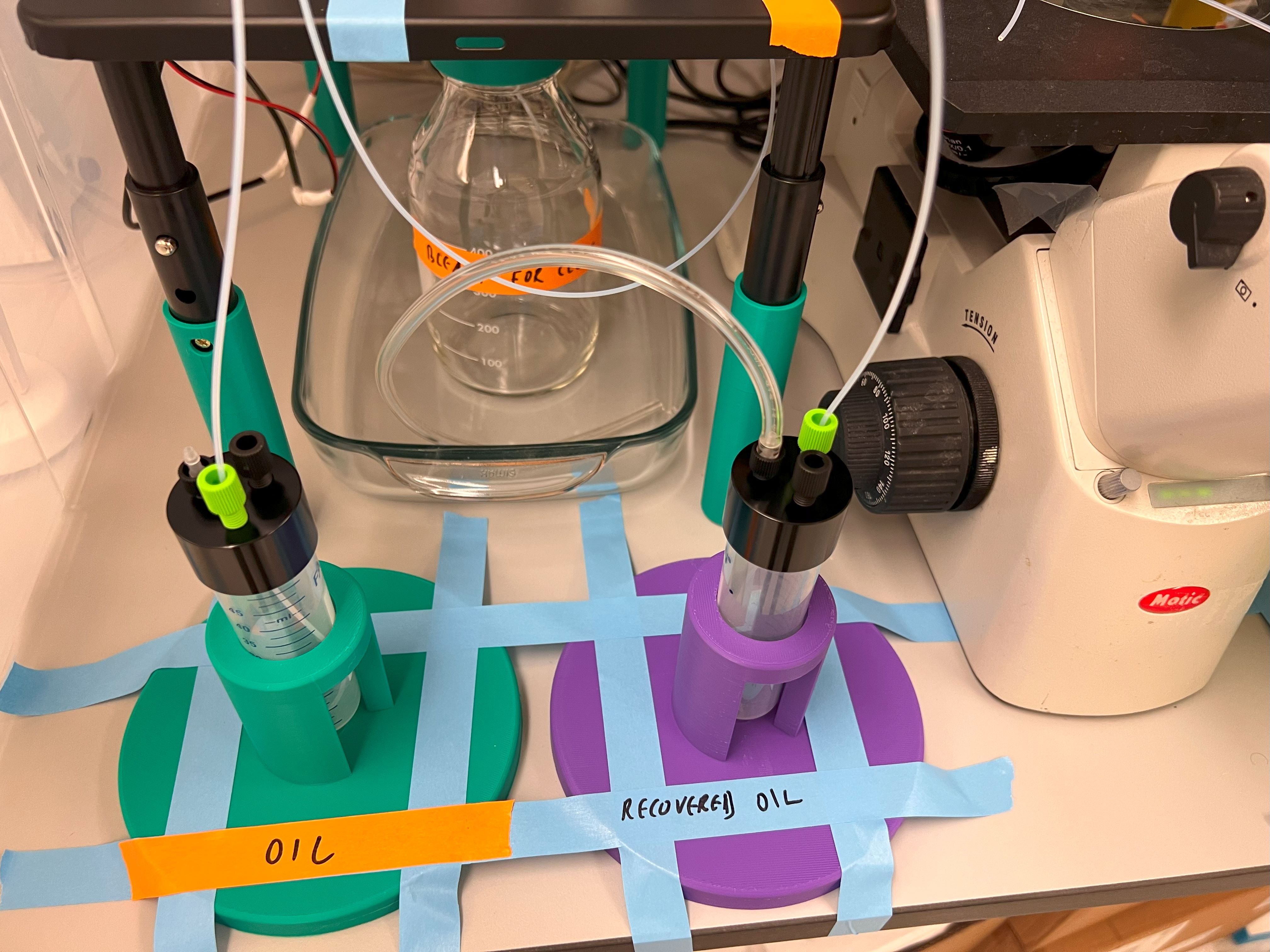
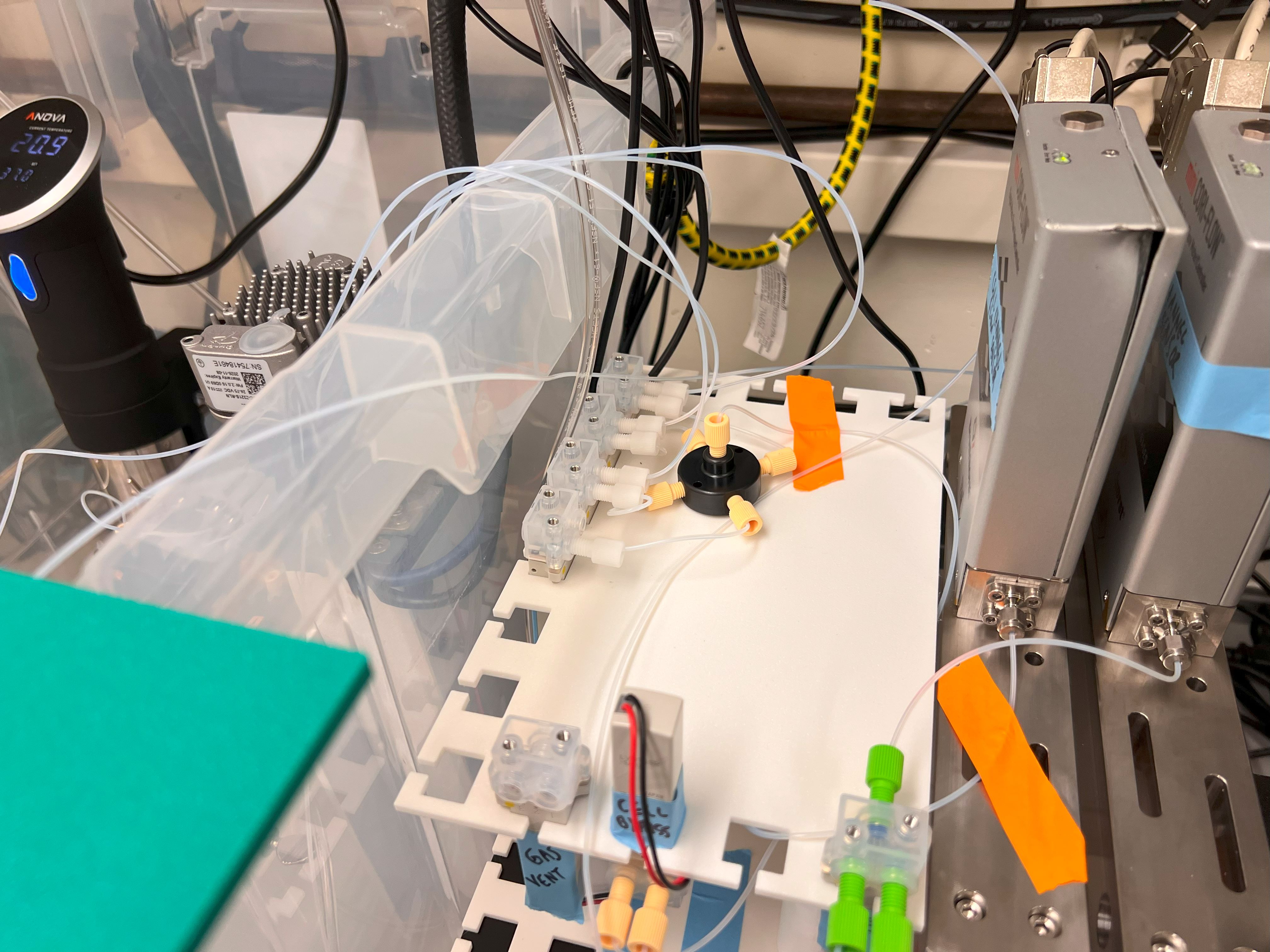
.jpg)