Instructions for the ChronoSeq Device assembly from Individual Components

Design of equipment.

Our device design addresses several challenges not present in the original Dropseq system (See Figure Below). First, extended cell viability. We maintain cell suspension viability for experiments lasting 2 hours or longer, compared to typical 30-minute Dropseq runs. Second, cross-contamination prevention. We implemented a washing system to remove unused cells or beads between samples. Third, sample isolation. We designed a system to prevent mixing wash fluid with droplets. To address these challenges, our device operates in two main phases during each injection cycle. 1. Flushing phase that clears fluid lines of residual beads or cells from previous injections. 2. Injection phase that precisely introduces cells and time-tagged beads into the microfluidic chip. This integrated system enables controlled, sequential introduction of cells and time-tagged beads, capturing gene expression dynamics across multiple time points in a single experiment.

ChronoSeq vs Dropseq comparison

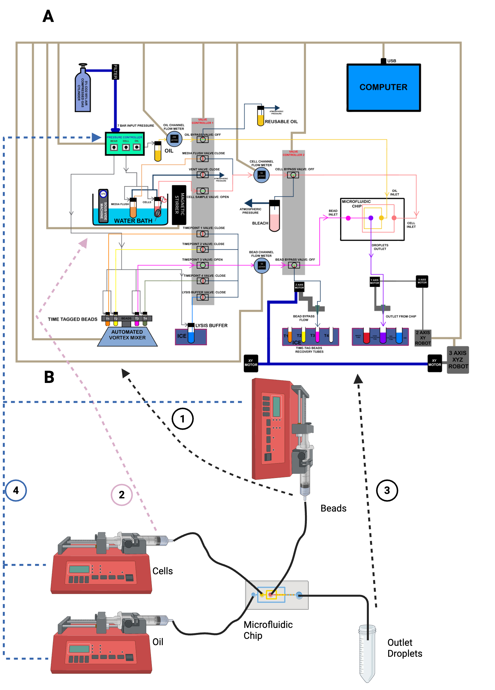
The Figure above compares the ChronoSeq device (A) with Dropseq device (B).

The ChronoSeq device is controlled via serial connections to a computer, which coordinates the actions of its various components, while the Dropseq device works by setting flow rates manually on syringe pumps. Some key features distinguish the ChronoSeq device:

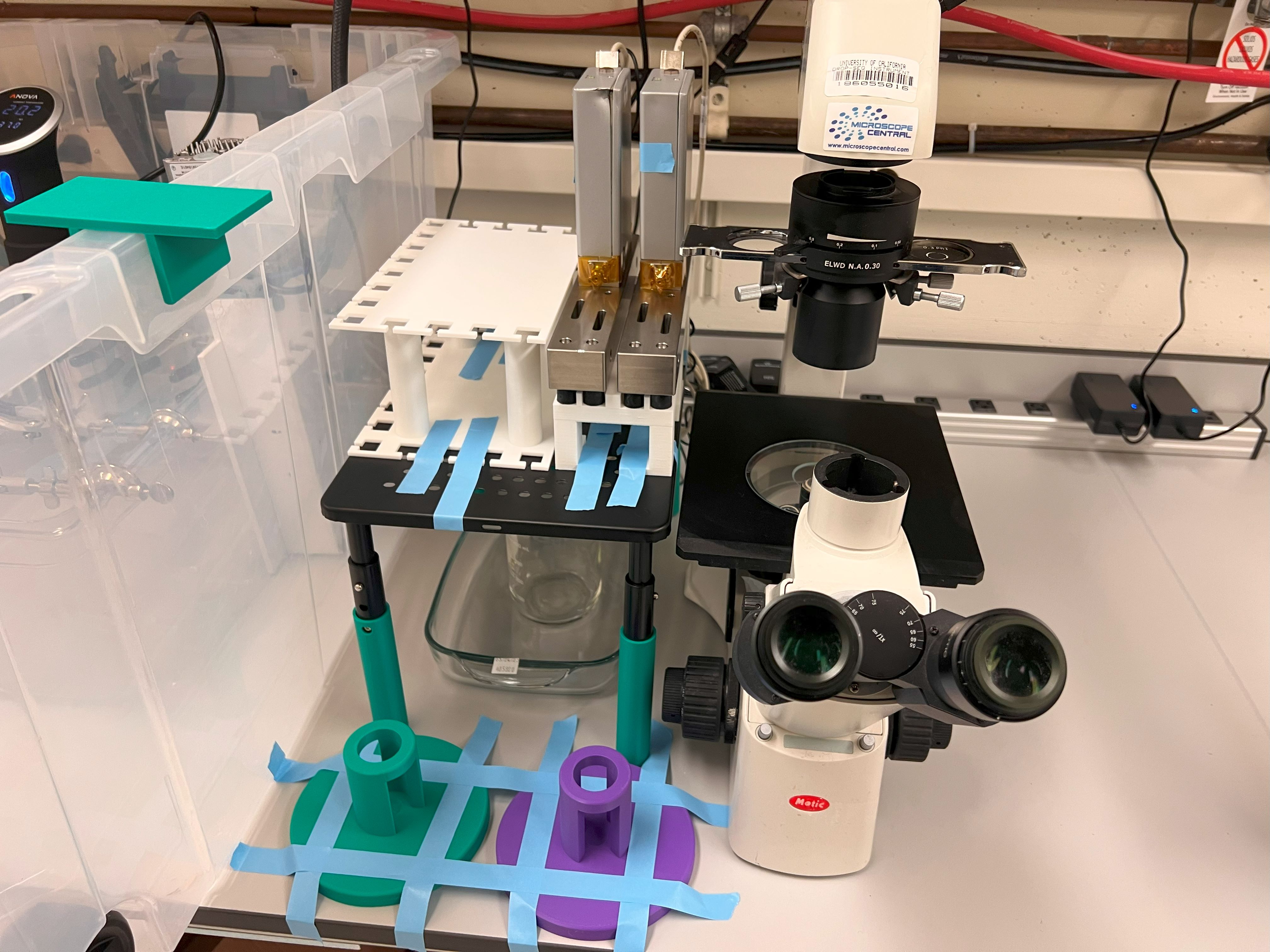
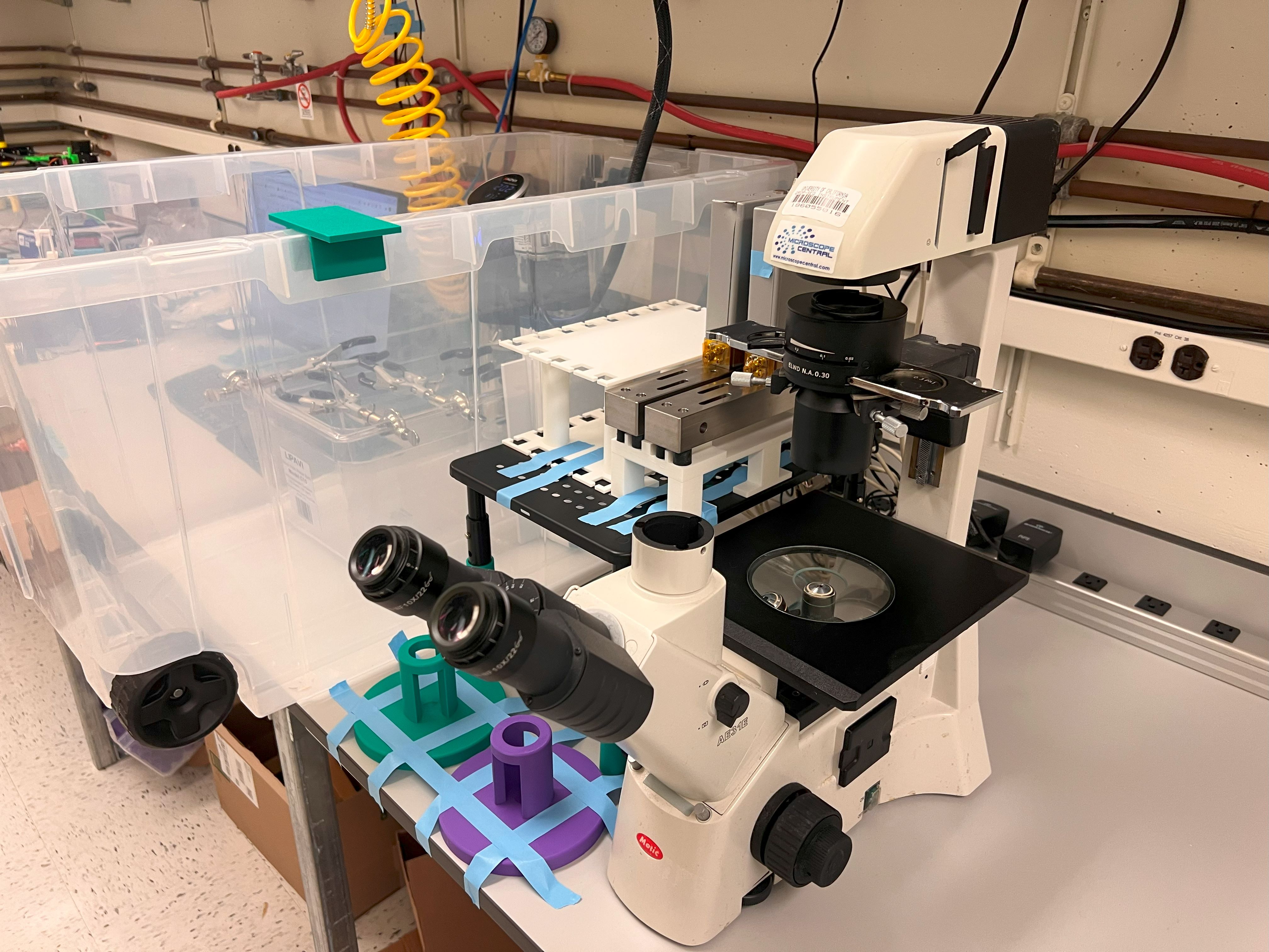
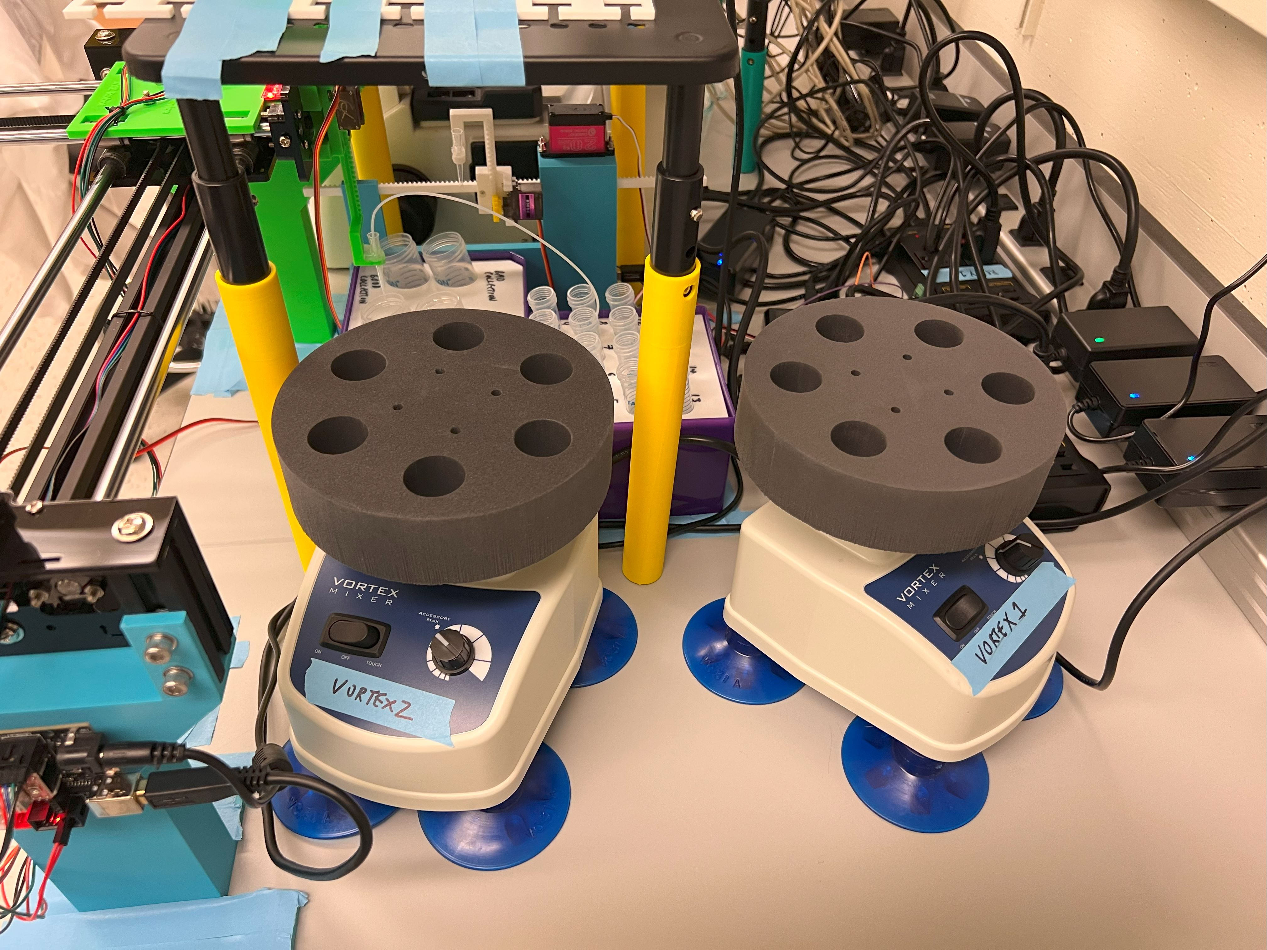
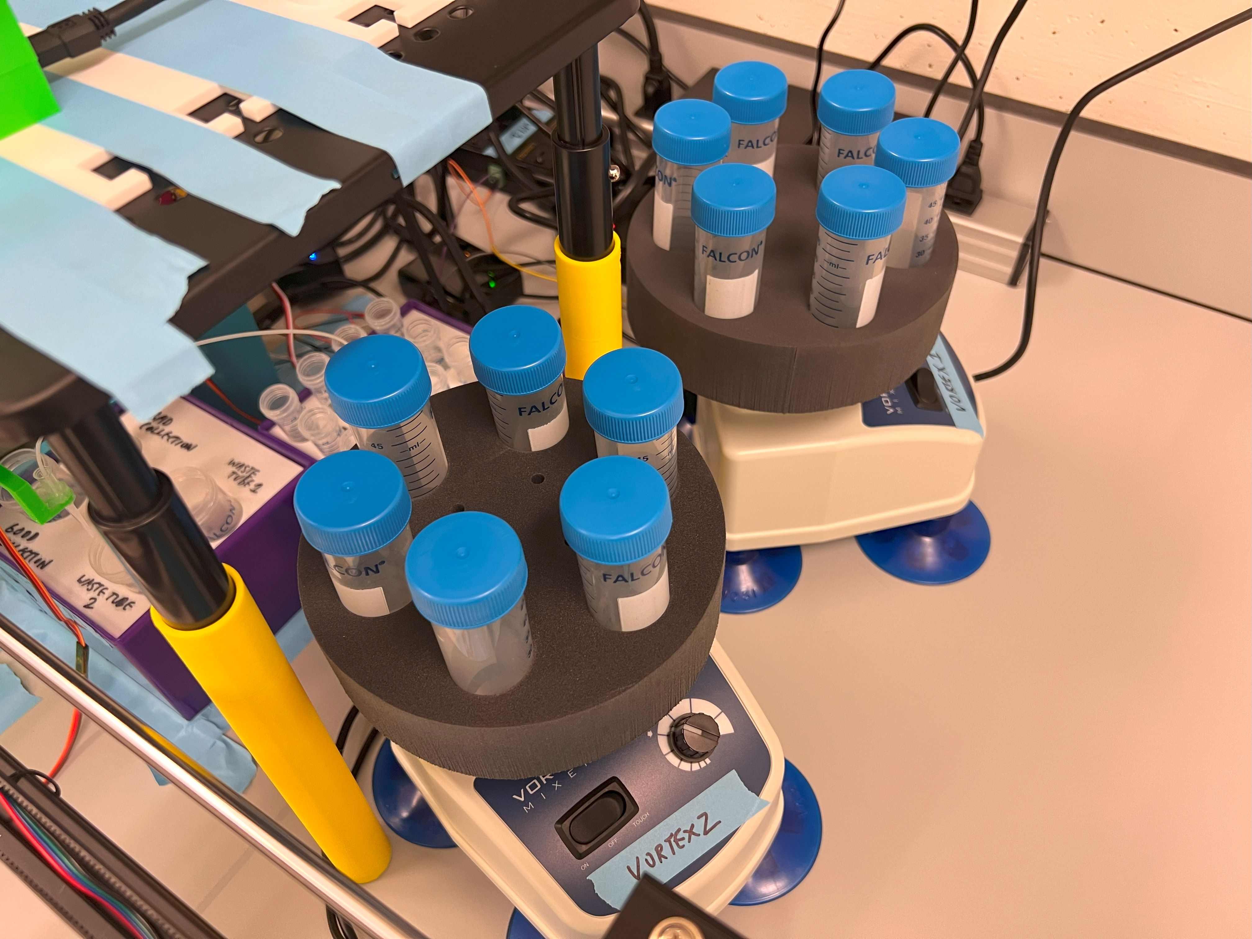
  1. Bead handling: ChronoSeq incorporates an automated vortex mixer to keep the beads evenly suspended before injection. Dropseq uses a magnetic stirrer for bead suspension, which leads to high dead volumes and complicates automation for multiple time-tags. ChronoSeq allows for the easy addition of more time-tags in the future if necessary. Additionally, loading and unloading the beads is simplified; we can directly screw a new 50 mL tube containing beads into the reservoir. The time-tagged bead reservoirs are connected to timepoint valves, which facilitate the selection of the appropriate time-tagged beads for injection into the microfluidic chip.
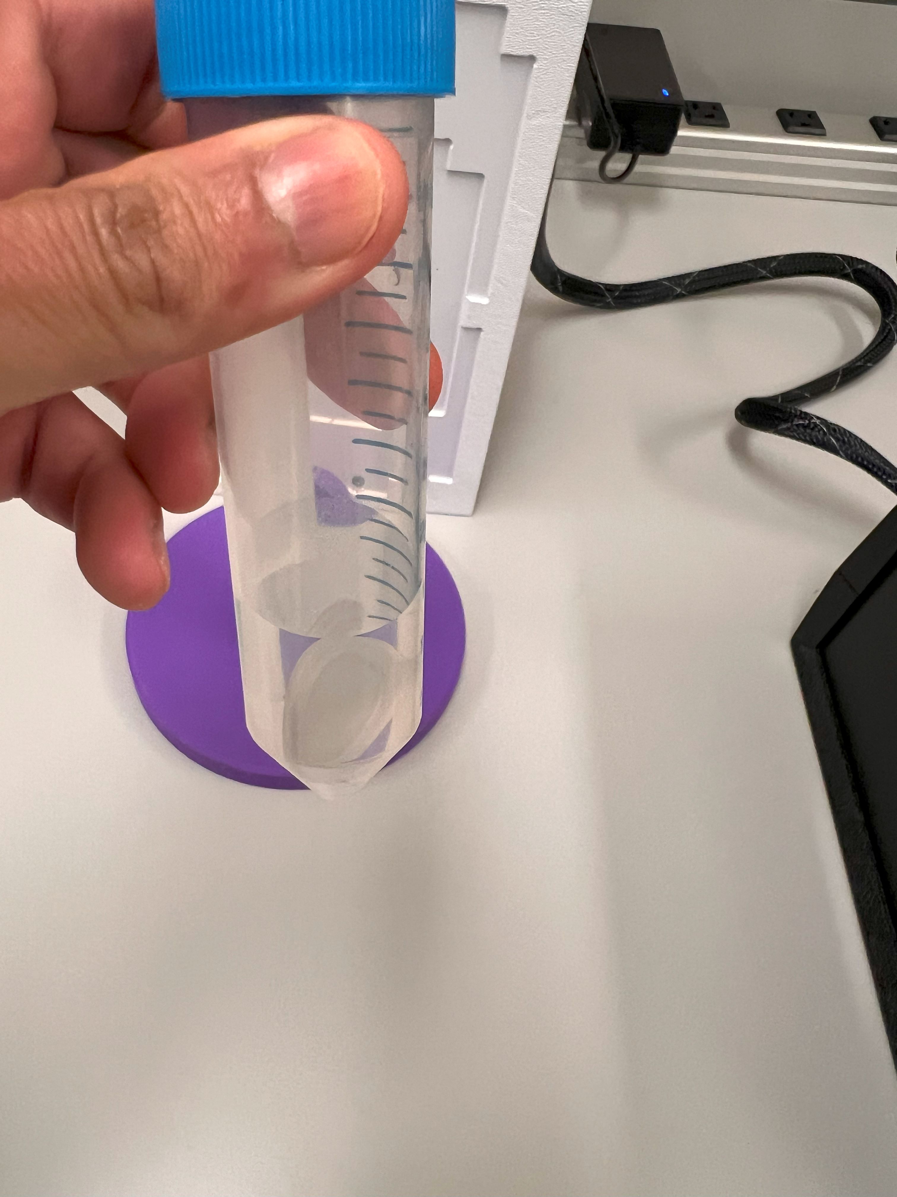
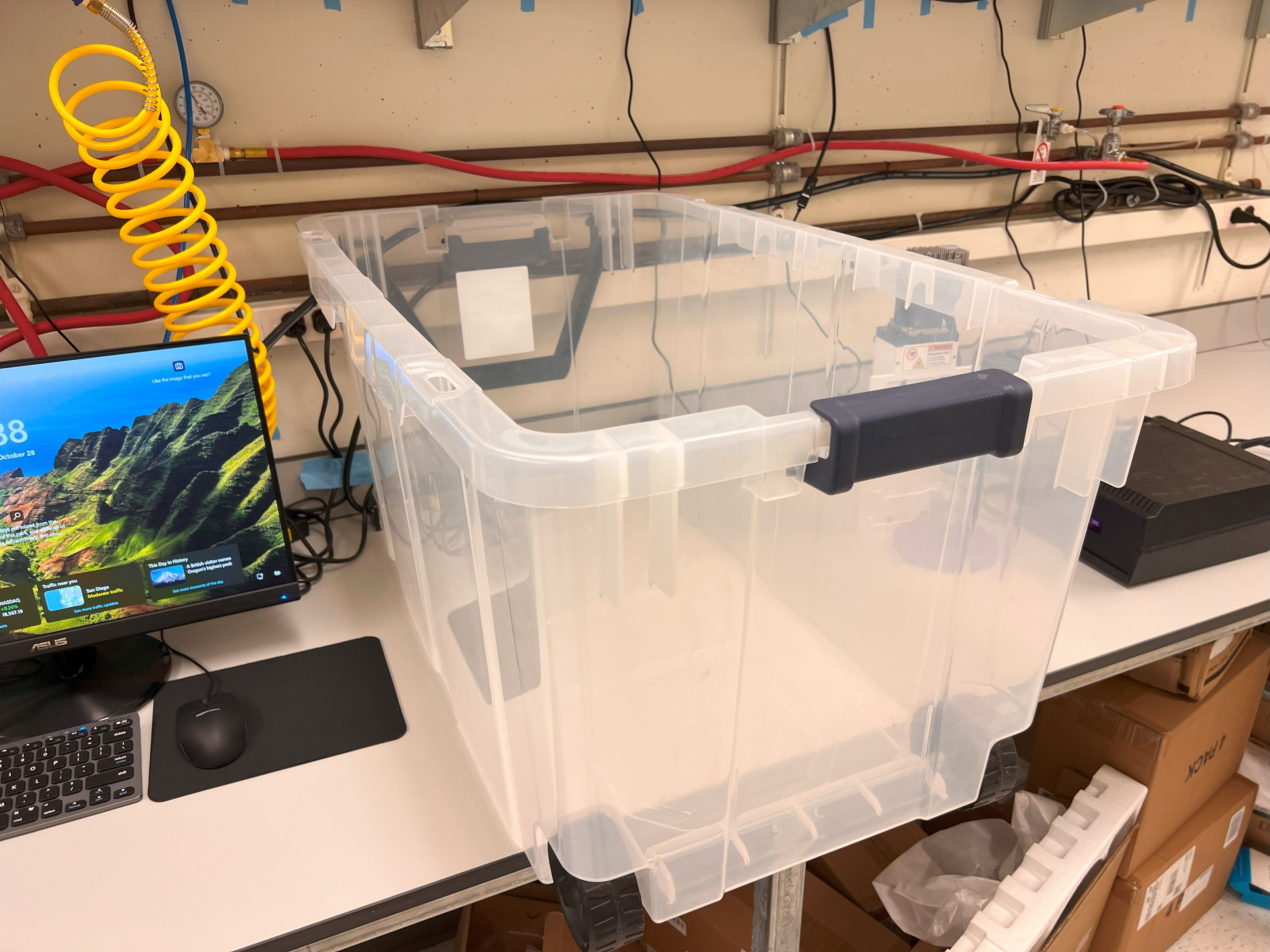
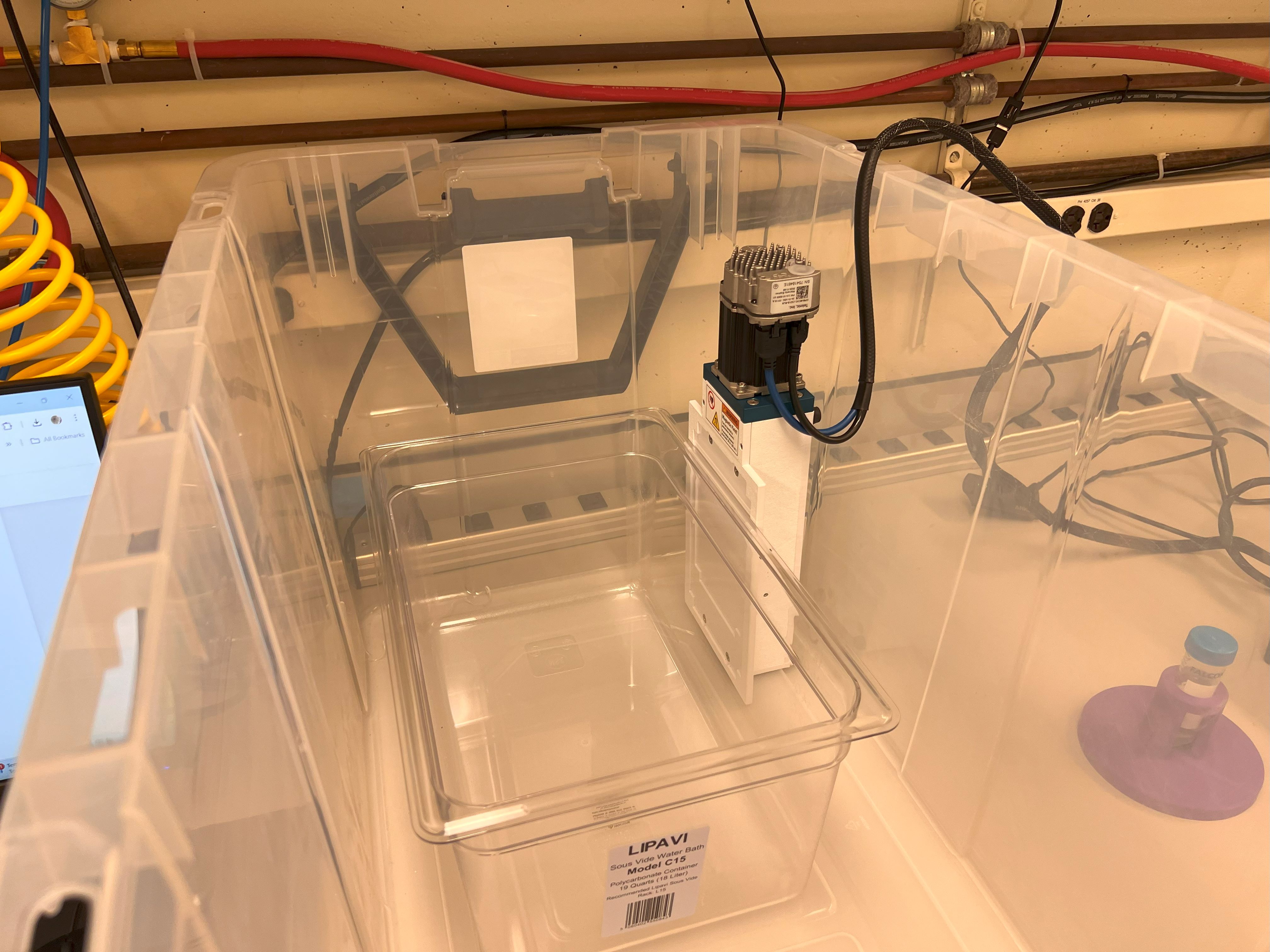
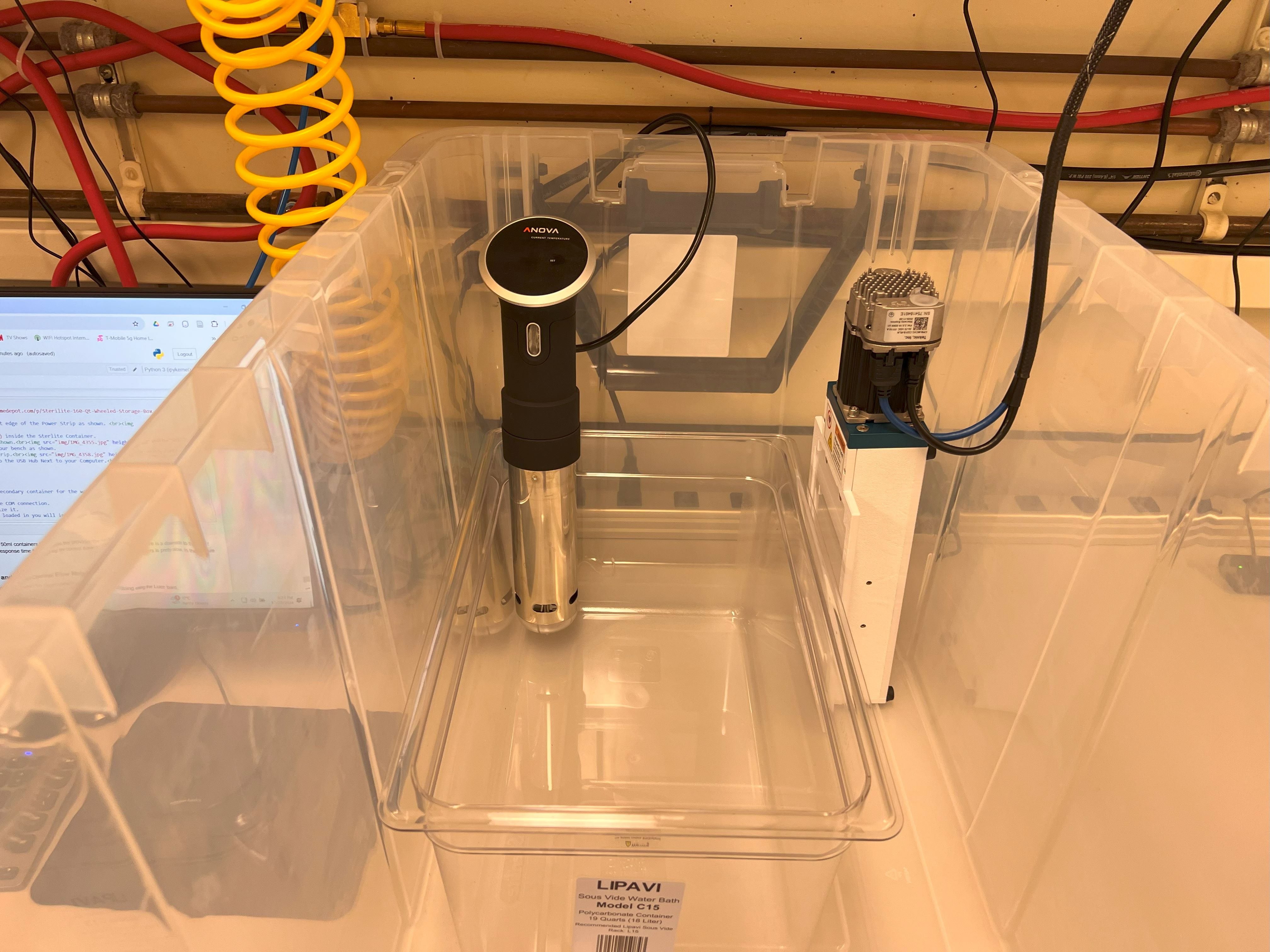
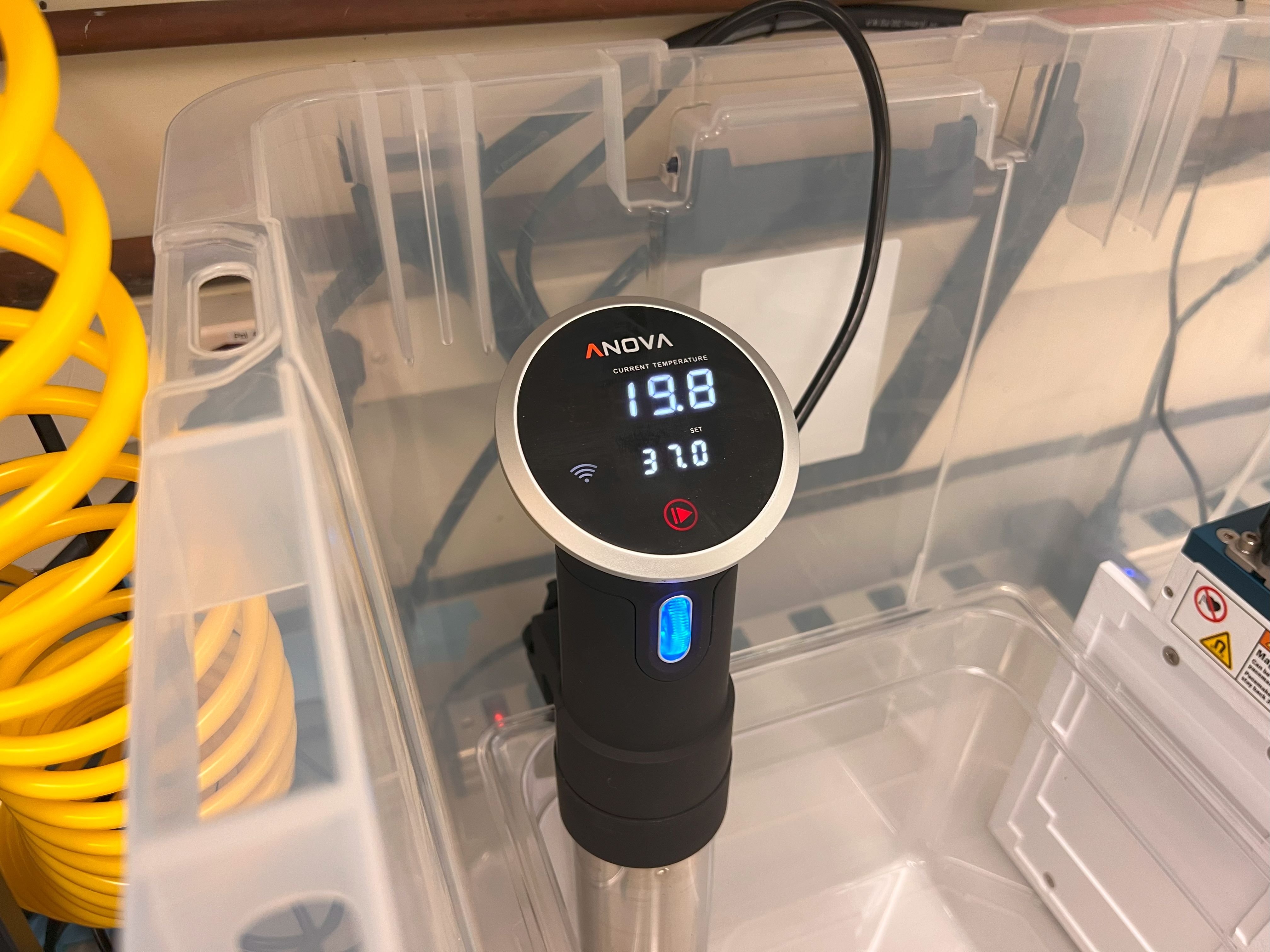
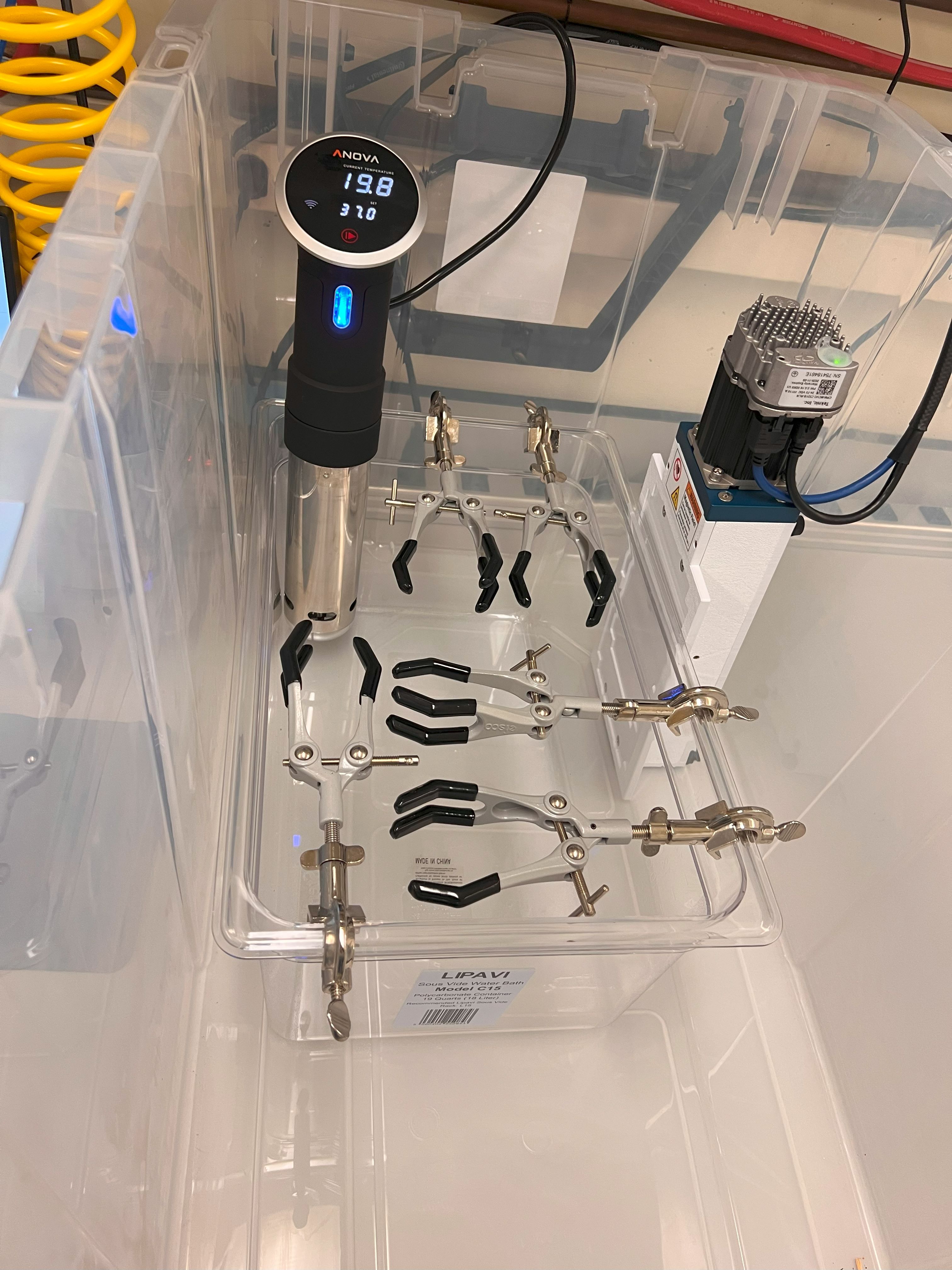
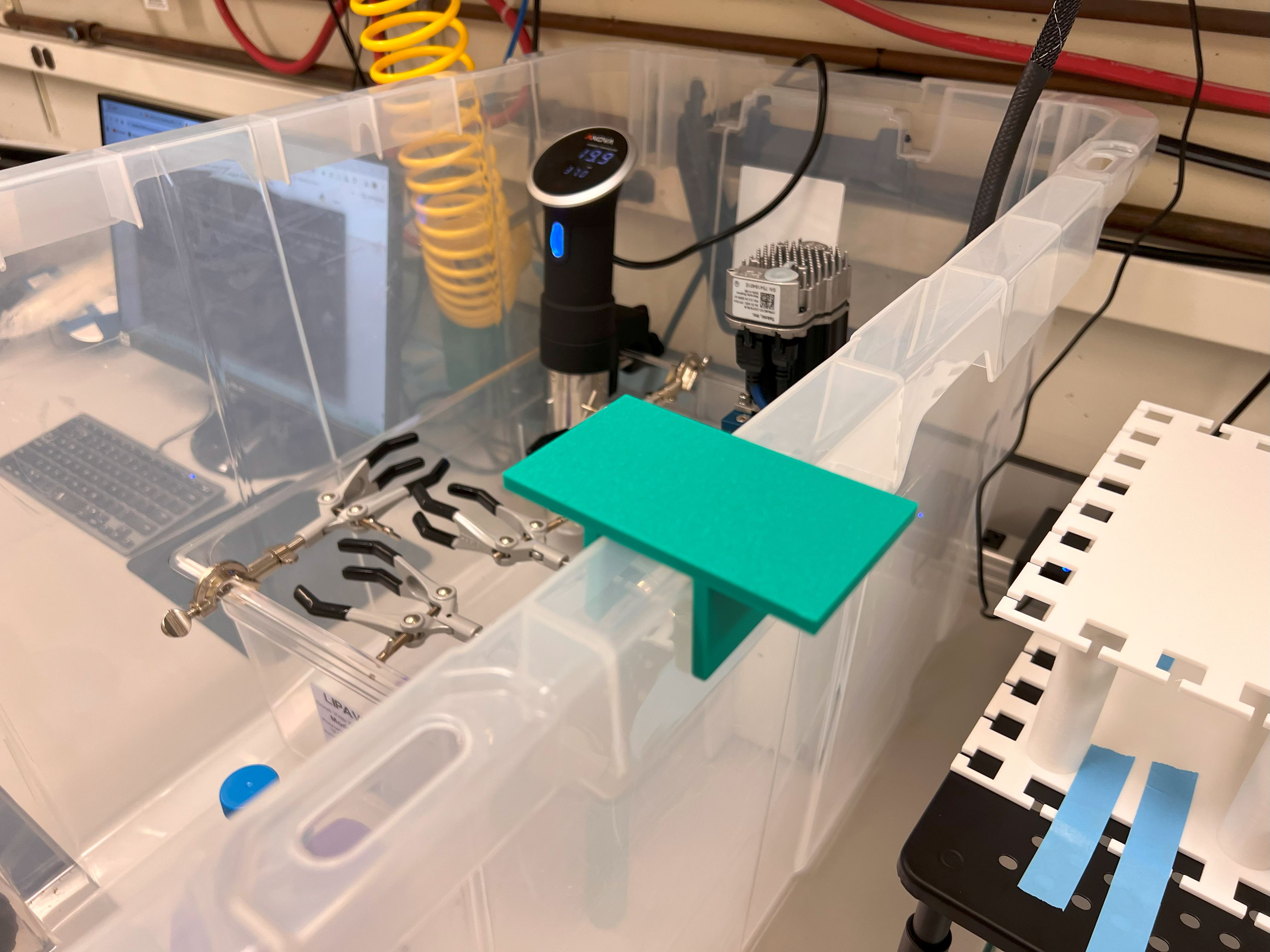
  2. Cell culture system: In the Dropseq device, cells are directly loaded into a syringe for injection, typically running for 15 to 30 minutes. However, our goal is to maintain cell viability for at least 2 hours. Leaving cells at room temperature without growth media and in the absence of 5% CO2 can lead to excessive cell death and unwanted perturbations. To address this, we have integrated a cell culture system directly into the ChronoSeq device, featuring a water bath to maintain cells at 37°C, along with a 5% CO2 gas cylinder that serves as a pressure source and aids in cell culture. Furthermore, we can add additional tubes to culture multiple cell suspensions separately and use valves to select which cell suspension is injected into the microfluidic chip.
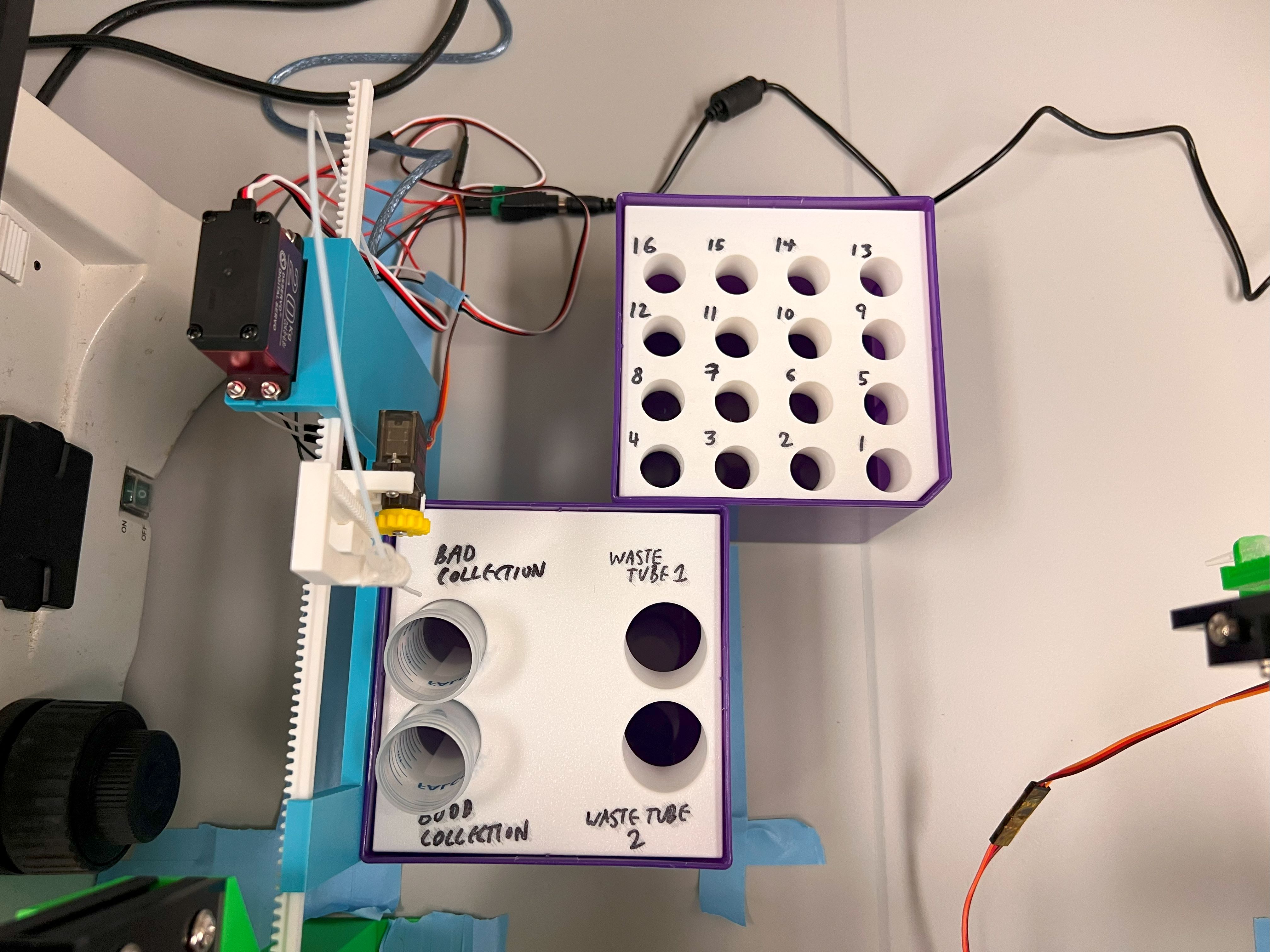
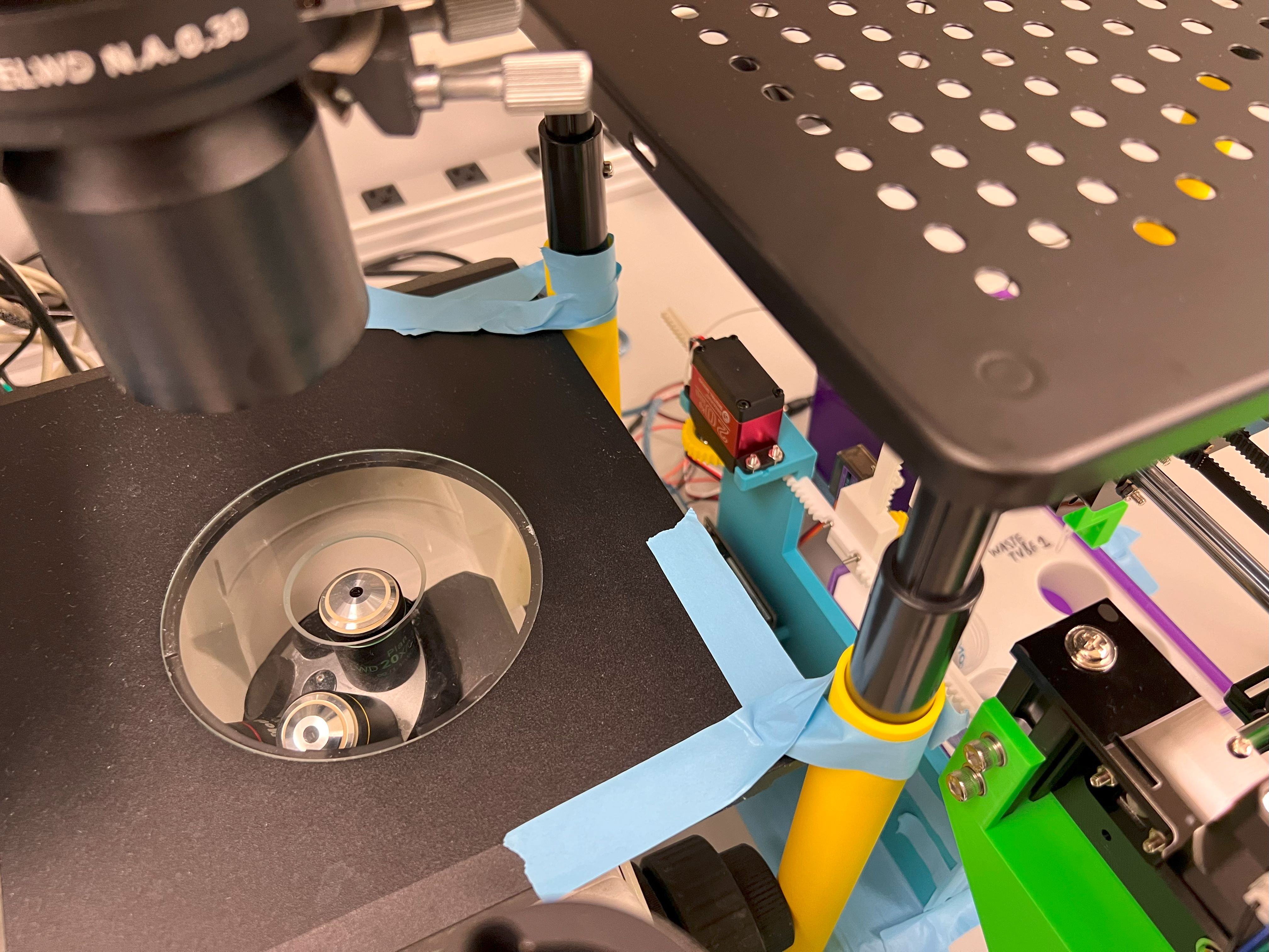
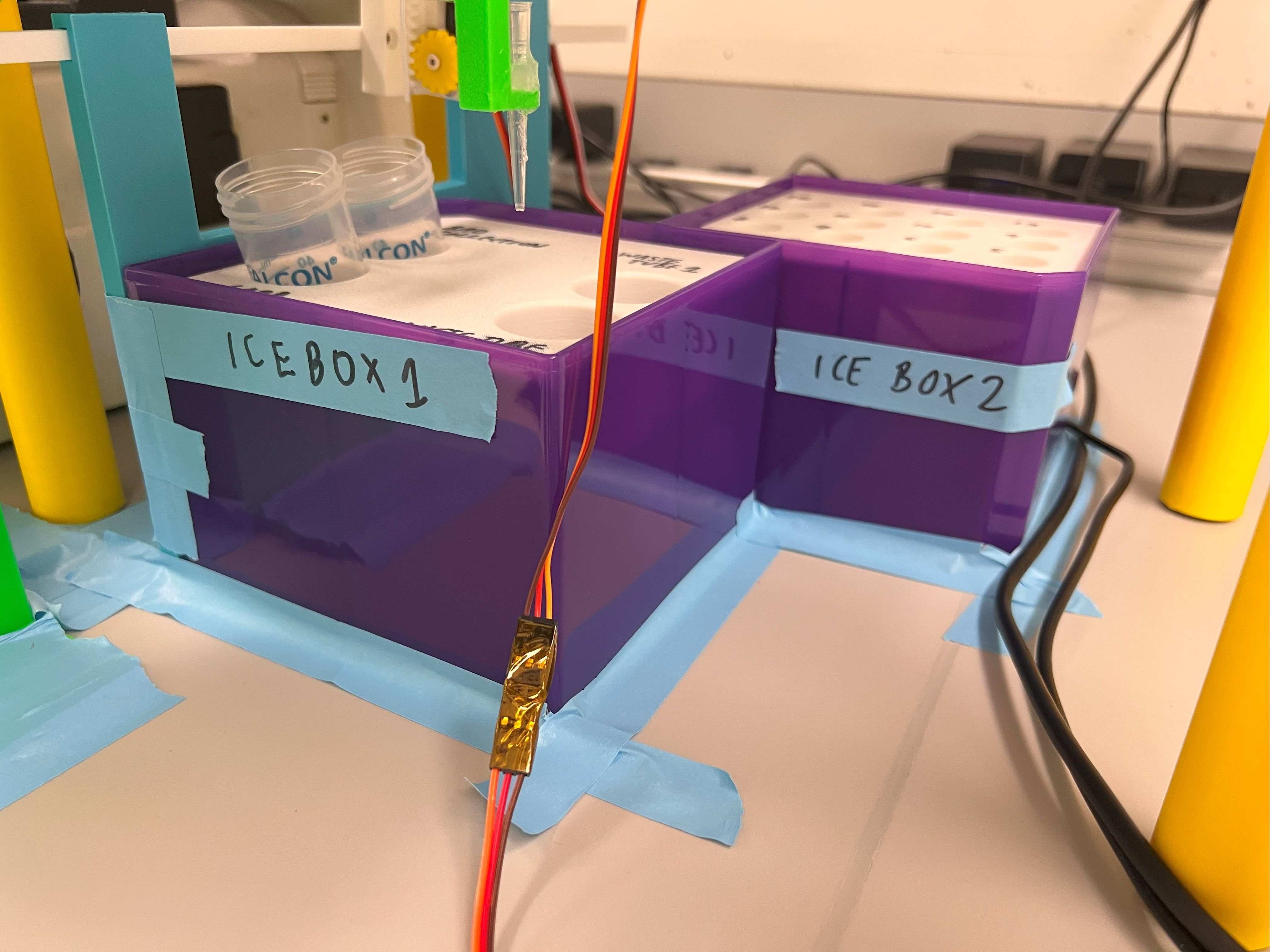
  3. Droplet collection: In the Dropseq device, droplets are collected directly in a 50 mL tube kept on ice. However, in our system, it is crucial to prevent the beads and cells from previous injections from mixing with those from new injections. To achieve this, we developed a washing system to clear the fluid lines of residual beads and cells. We also need to ensure that washing liquids and unused cell suspensions do not mix with the collected droplets. To solve this issue, we designed a robotic system that facilitates droplet collection and bead recovery. This robot automatically moves the outlet tubing to the correct tube, preventing the mixing of droplets with washing fluids. Additionally, it can recover unused beads from the fluid lines, minimizing waste and reducing experimental costs. Like the Dropseq device, the droplets in our system are also kept on ice using ice boxes.
  4. Flow control: In the Dropseq device, precise speed control is essential for droplet formation. Speeds that are too high can inhibit droplet formation, while low speeds can negatively impact throughput. To achieve this precise control, Dropseq employs syringe pumps, which allow direct manipulation of the syringe's squeezing rate. In our case, we require high flow rates for flushing and low flow rates for droplet formation. Low flow rates like Dropseq flow rates, are insufficient for quickly washing unused beads and cells from the device. Therefore, we implemented a compressed air pressure controller and flow sensors for each of the bead, cell, and oil channels. The compressed air controller enables rapid changes in flow rate, while the flow sensors provide the precise control needed for high-quality droplet formation during low flow rate operation.

3D Printing Parts

  • We used a Bambu Lab X1 Carbon to print the Parts.
    • 0.4mm Nozzle
    • Textured PEI Plate
  • We used PLA filament for our 3D Prints. Most Generic brands work quite well.
    • We found ELEGOO PLA to be reasonably priced.
    • Their spools were also neatly wound, reducing the chance of Print Failure.
    • You can choose from many different colors.
    • We don't recommend getting Translucent or Transparent PLA filaments.
      • The Filament runout sensor doesn't work well with these types of Filaments.
  • We generated several 3MF Files with all the Settings we used for the Print. You can open these files on the Orca Slicer.
  • The Original STEP Files and F3D Files can be found in the same directory.
  • Some of the prints included in this directory:
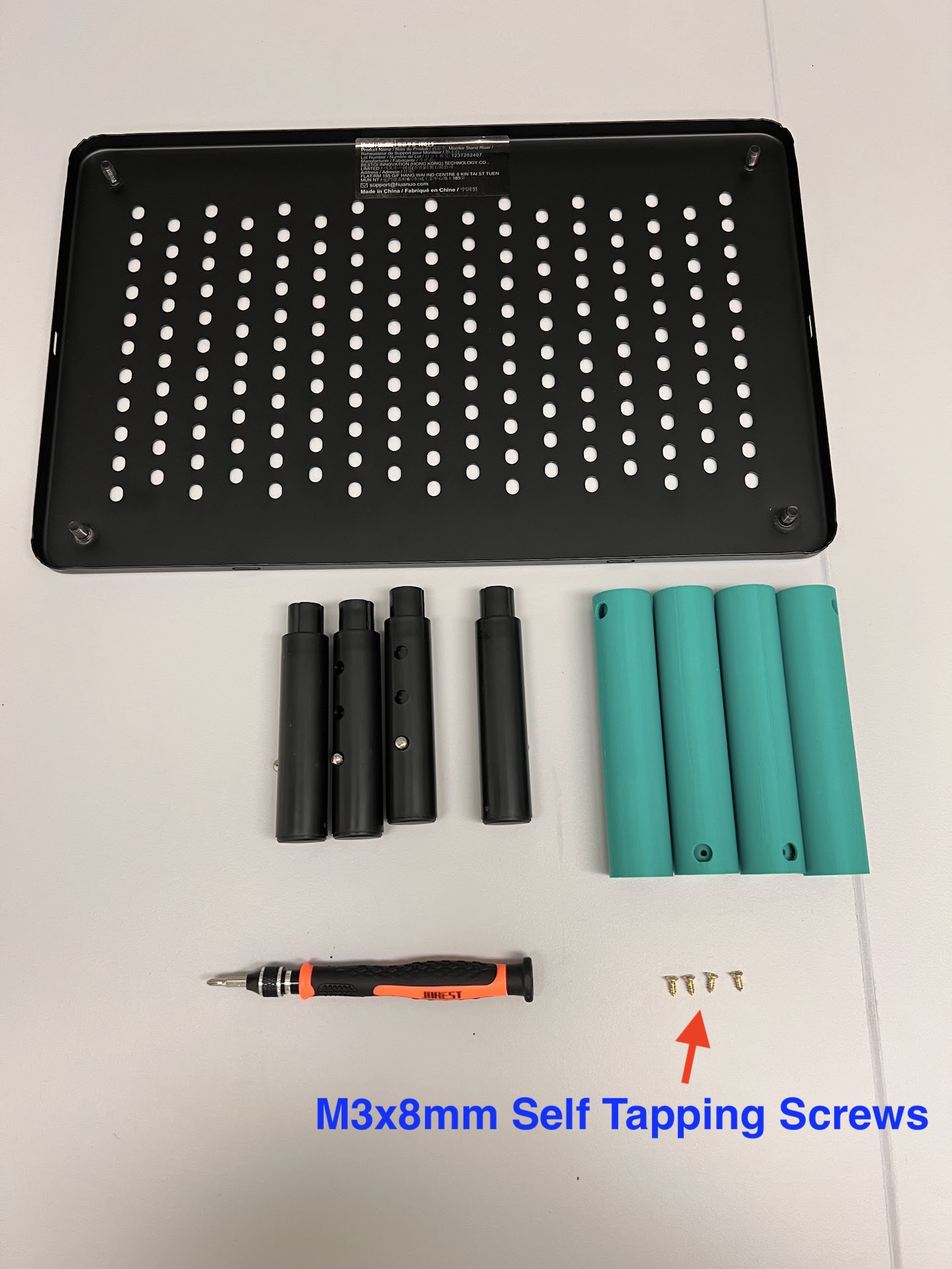
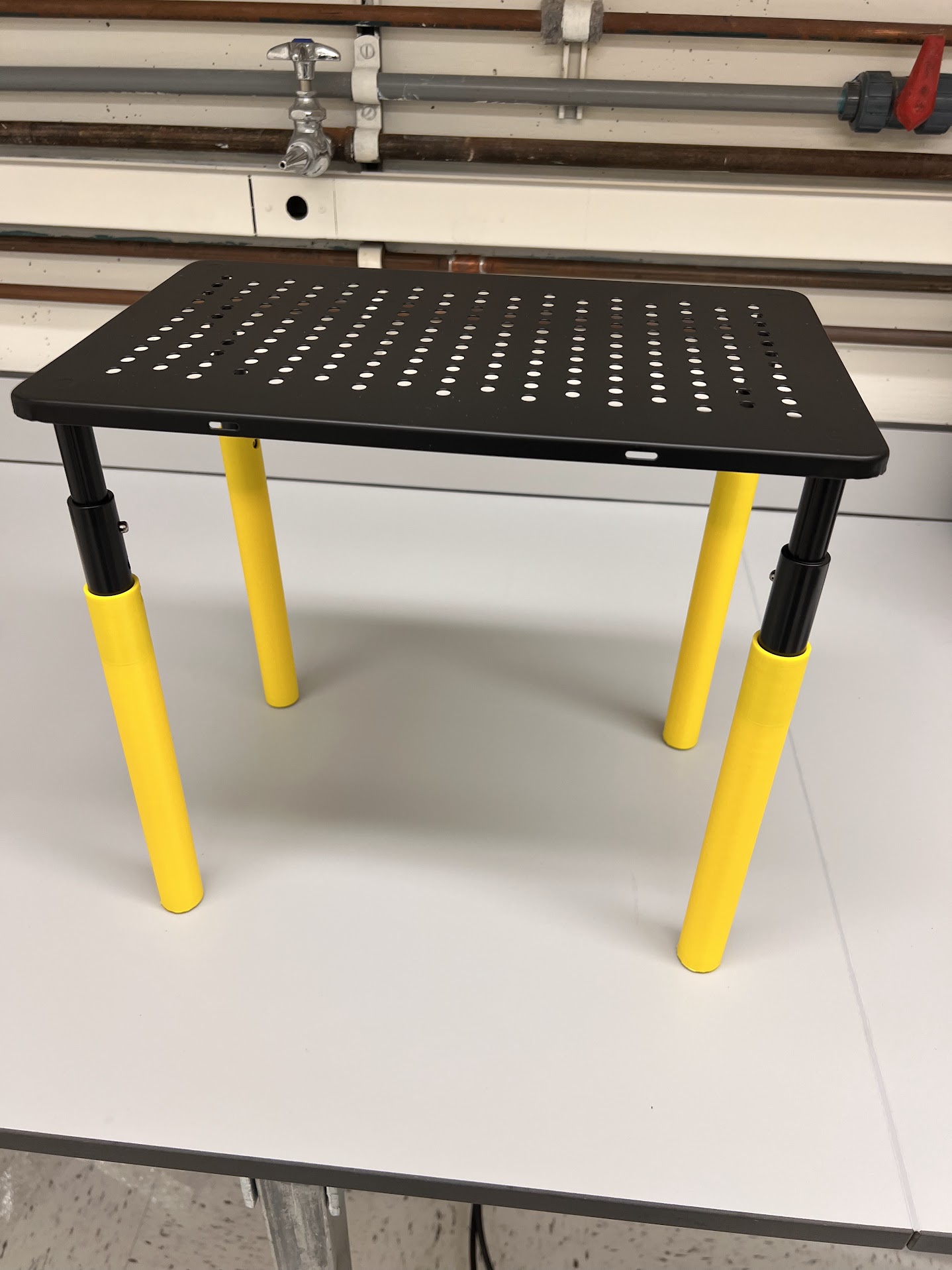
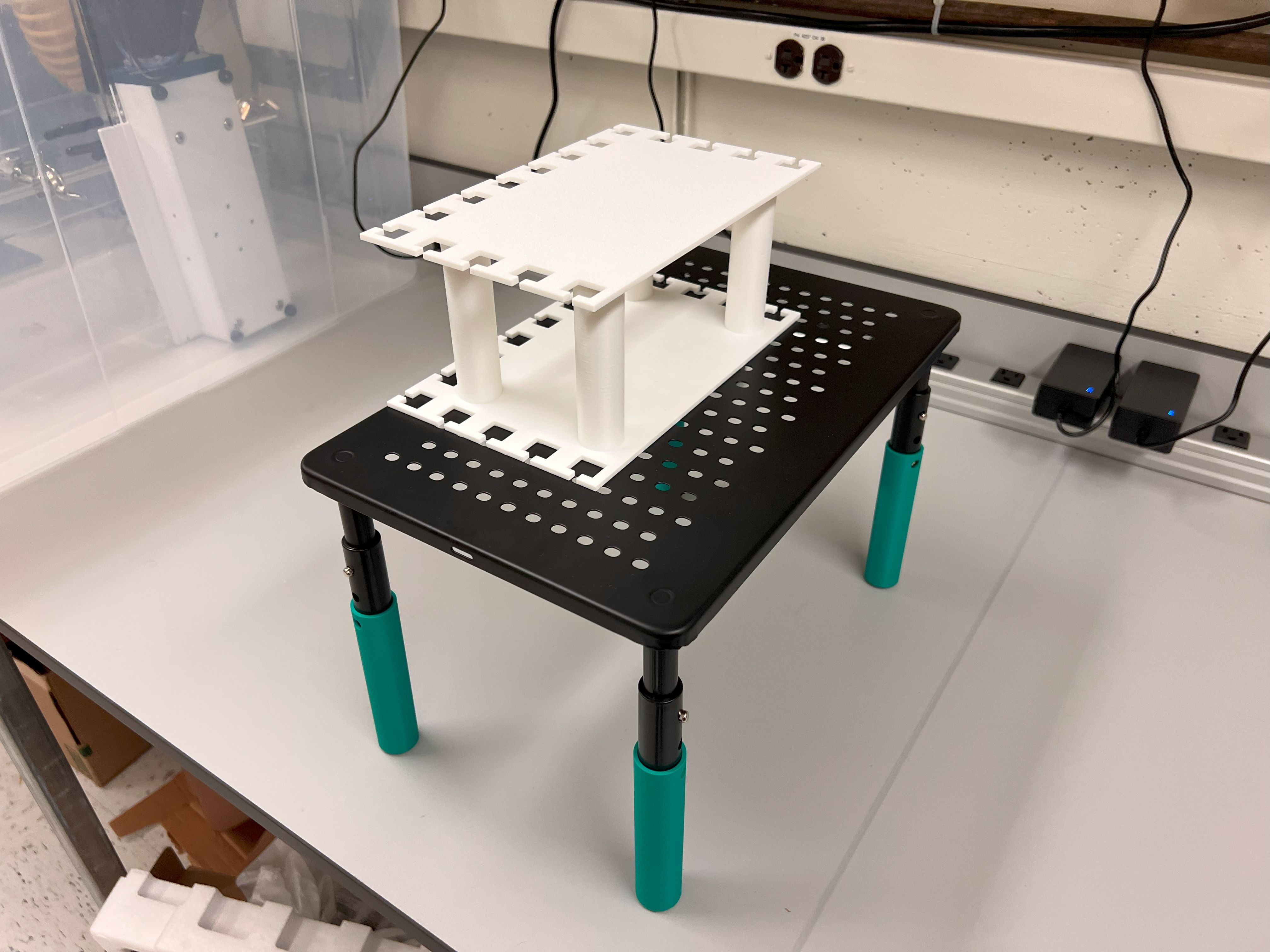
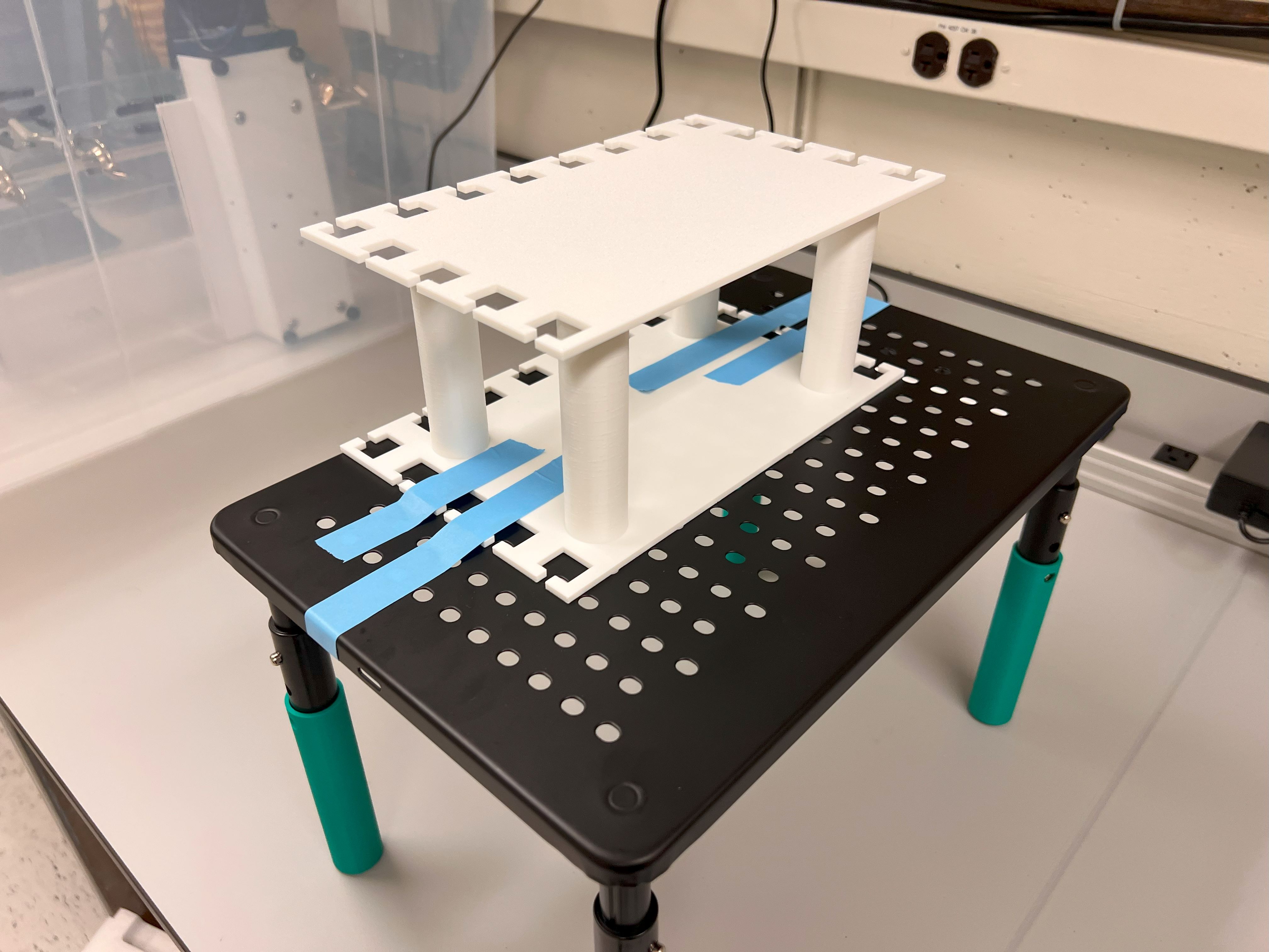
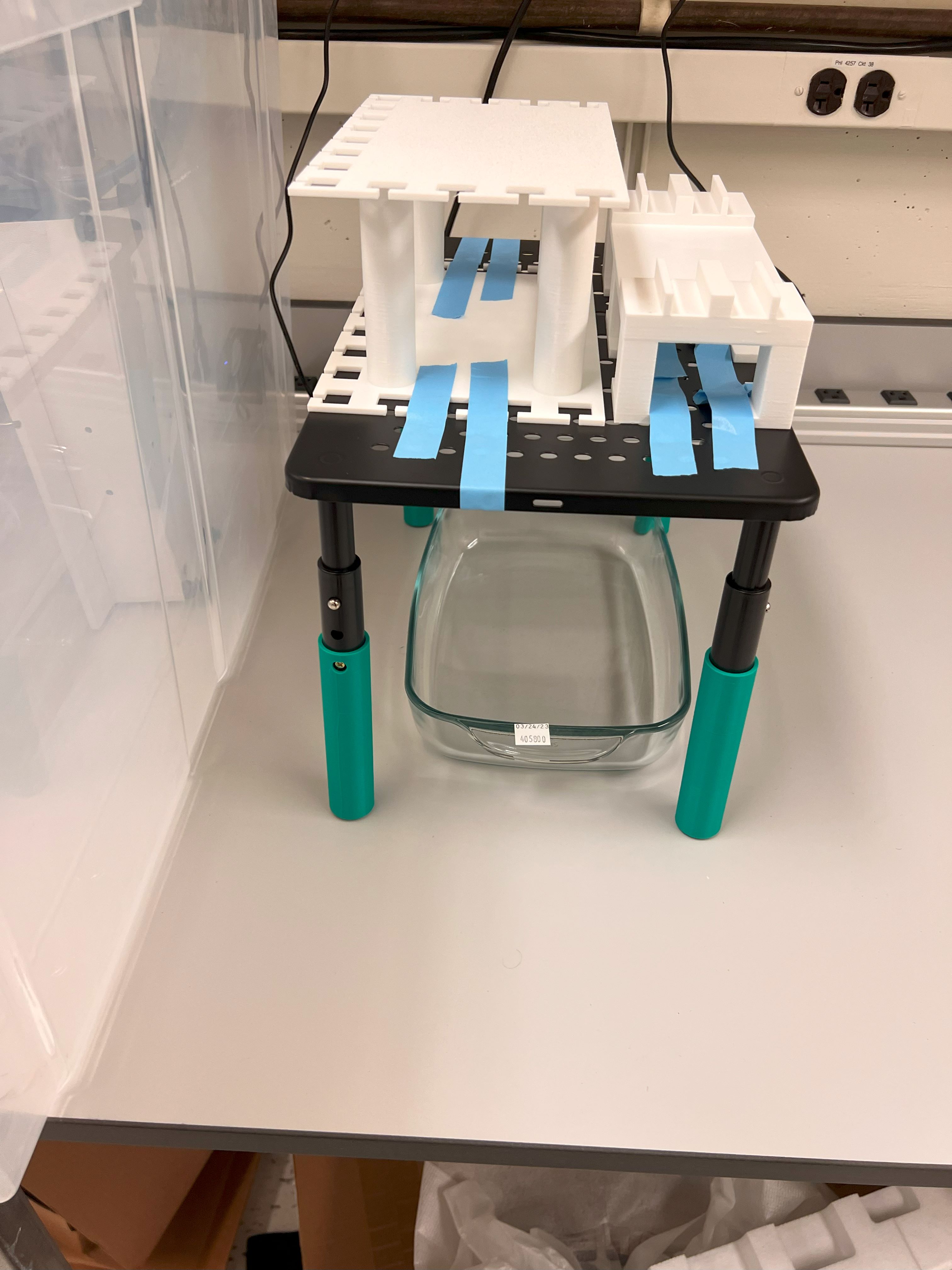
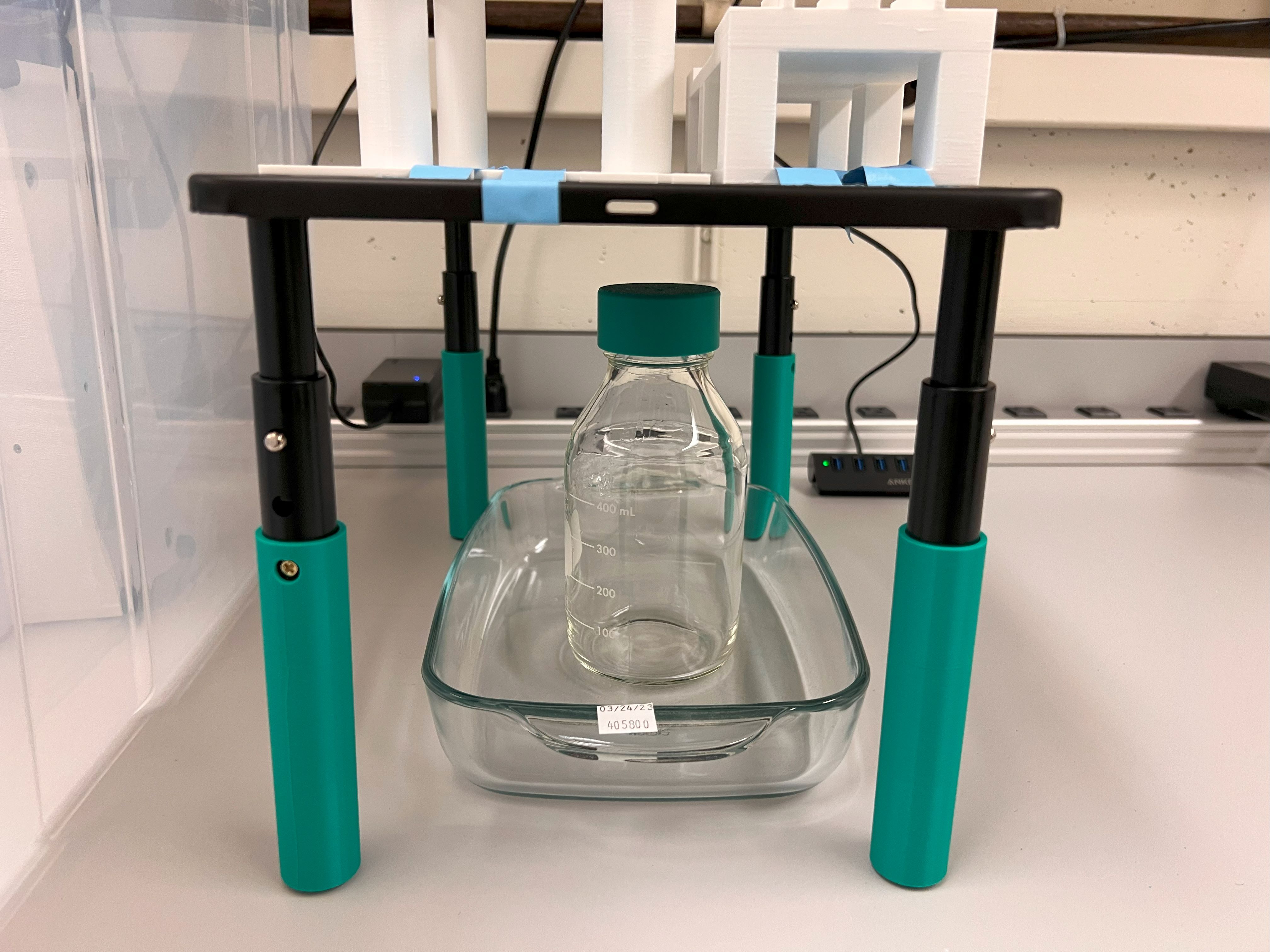
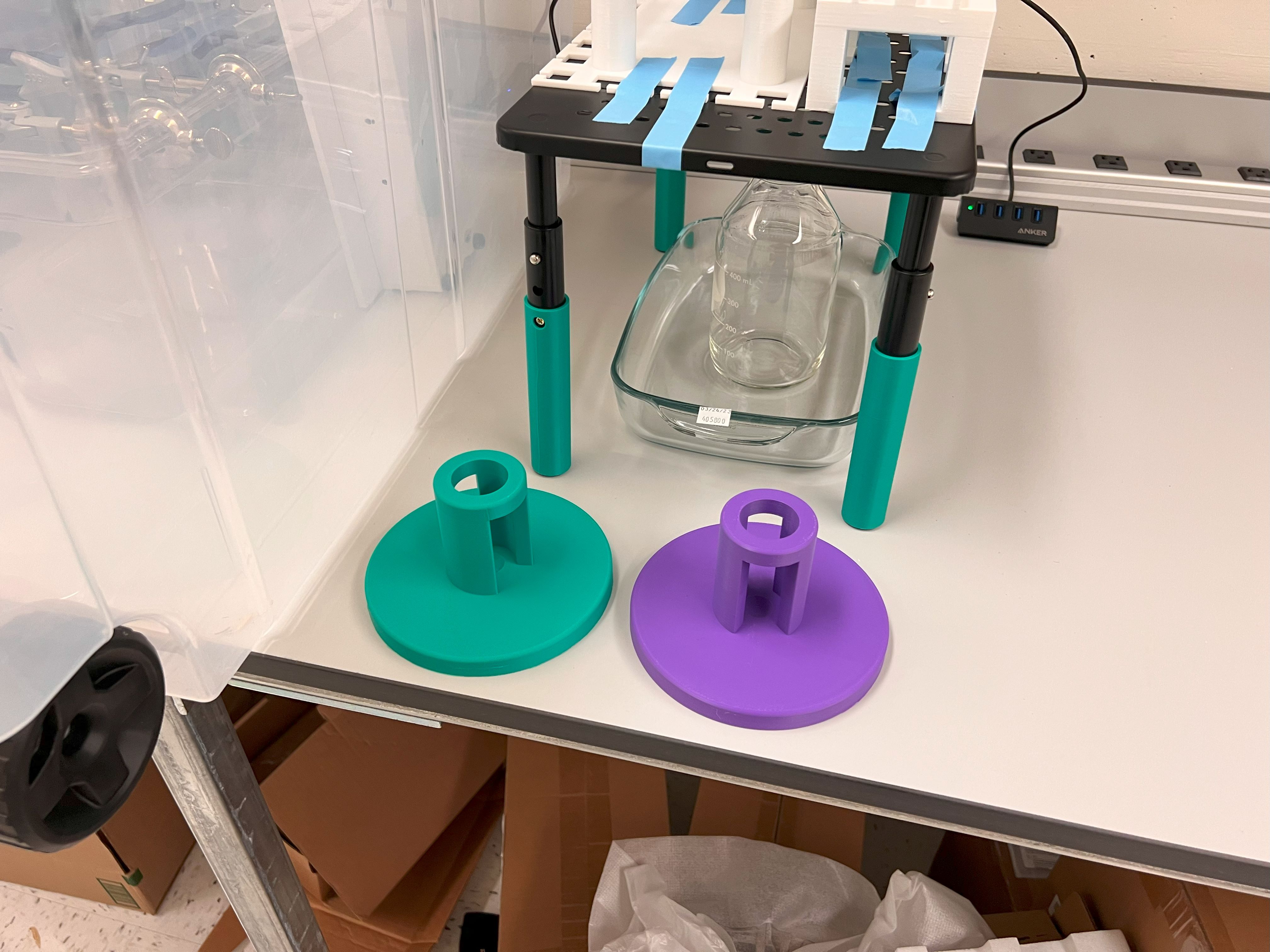
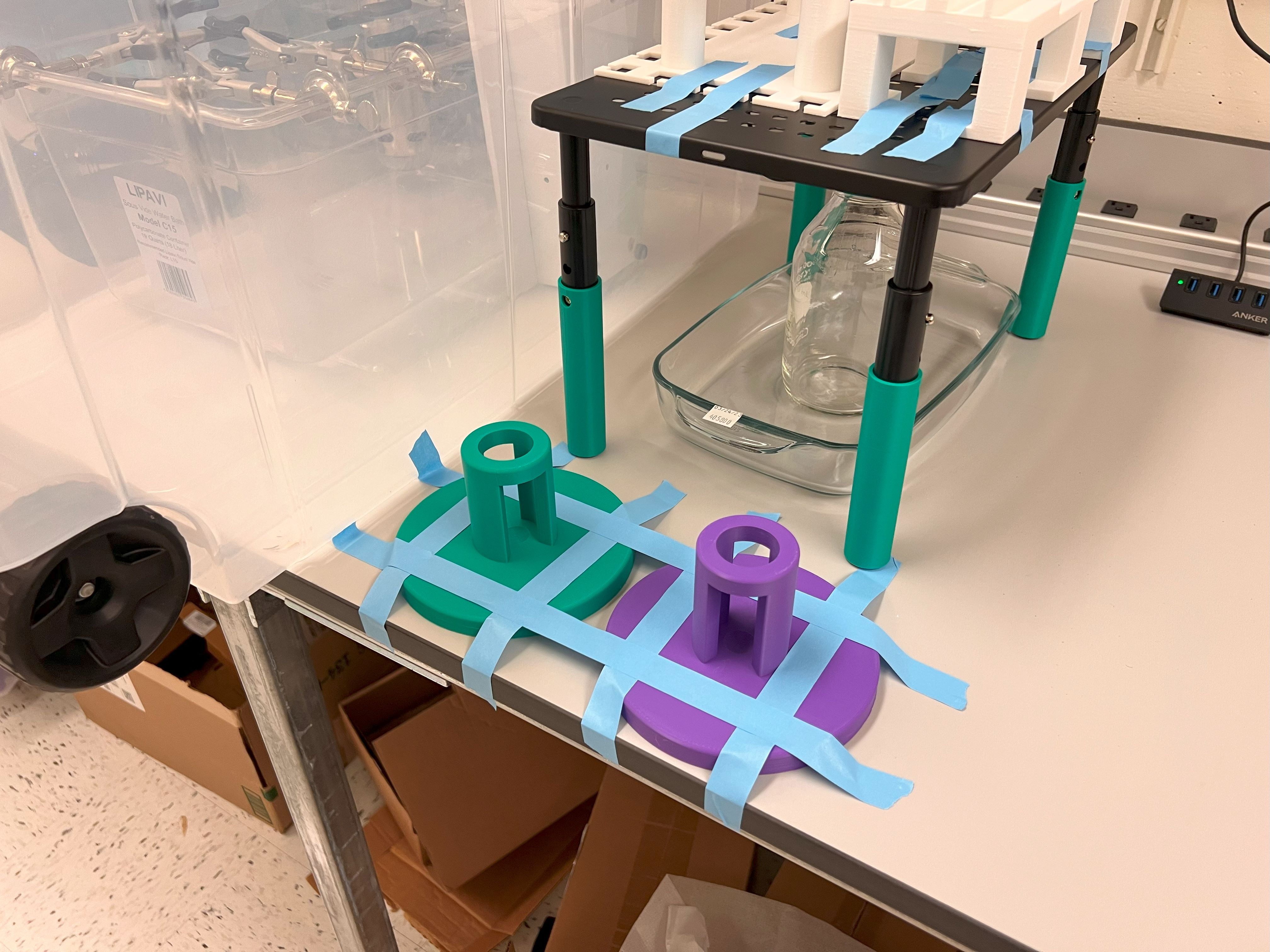
    • We will need to increase the height of two Monitor Risers for some of the ChronoSeq device components.
      • The riser on the right side of the ChronoSeq device is taller and you will need the Tallers legs for that one.
      • The riser on the right side of the ChronoSeq device is shorter and you will need the Shorter legs for that one.
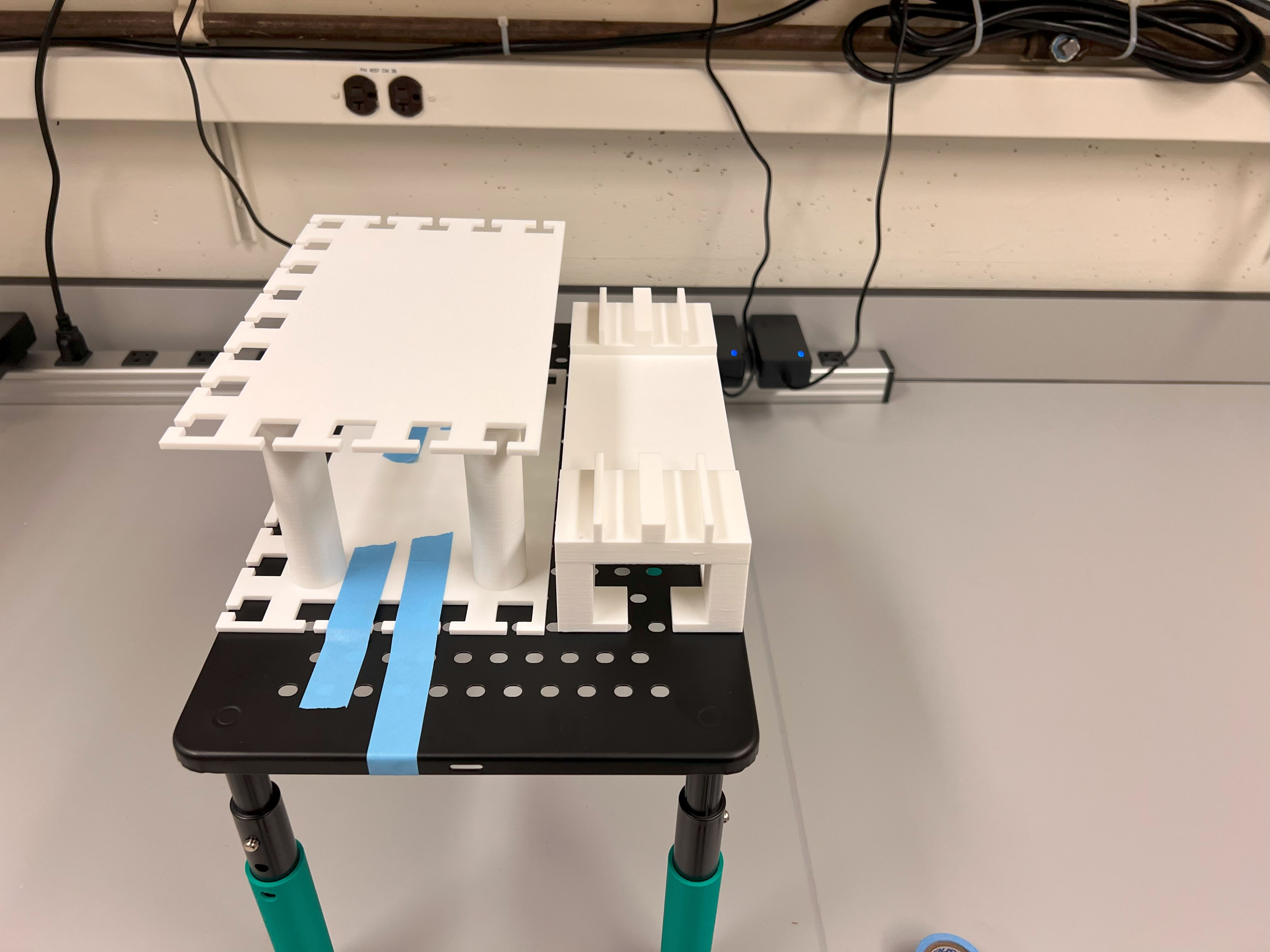
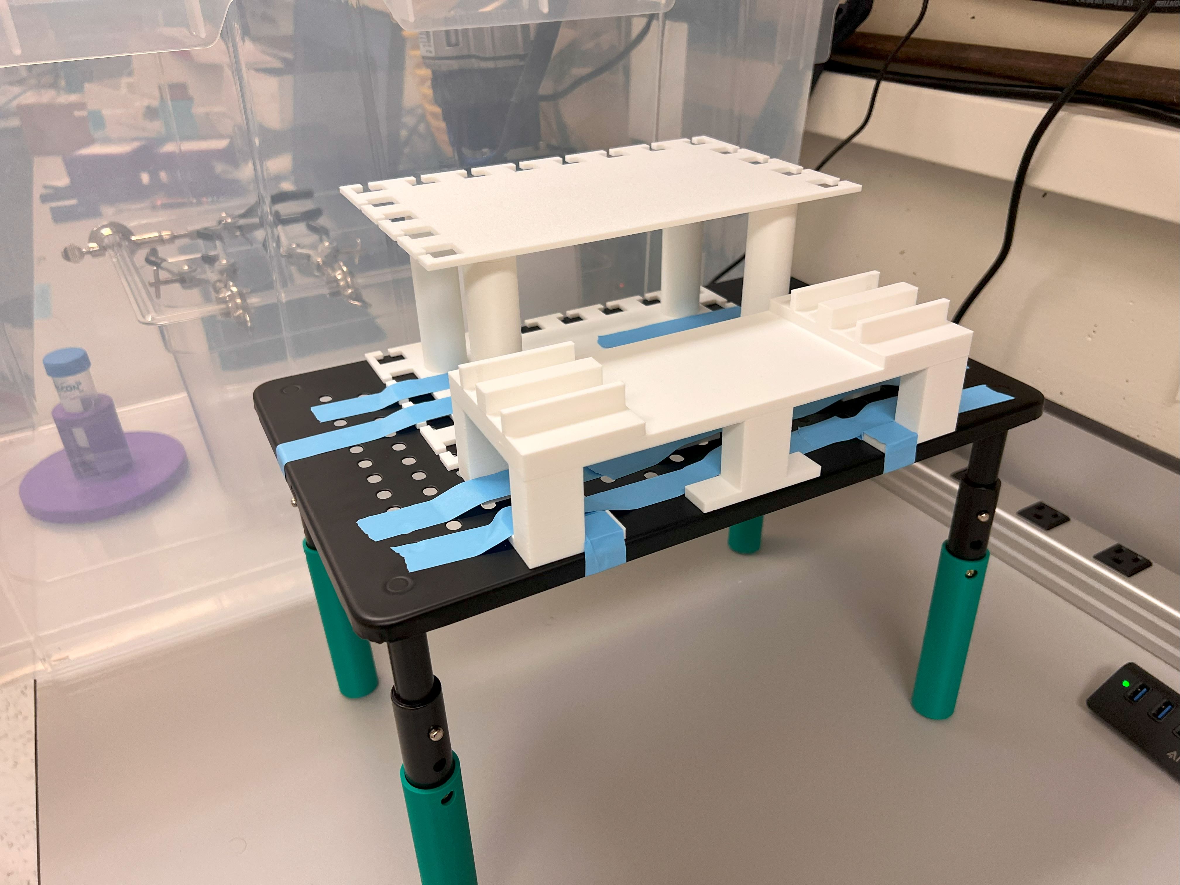
    • You will also need a Pipette holder.
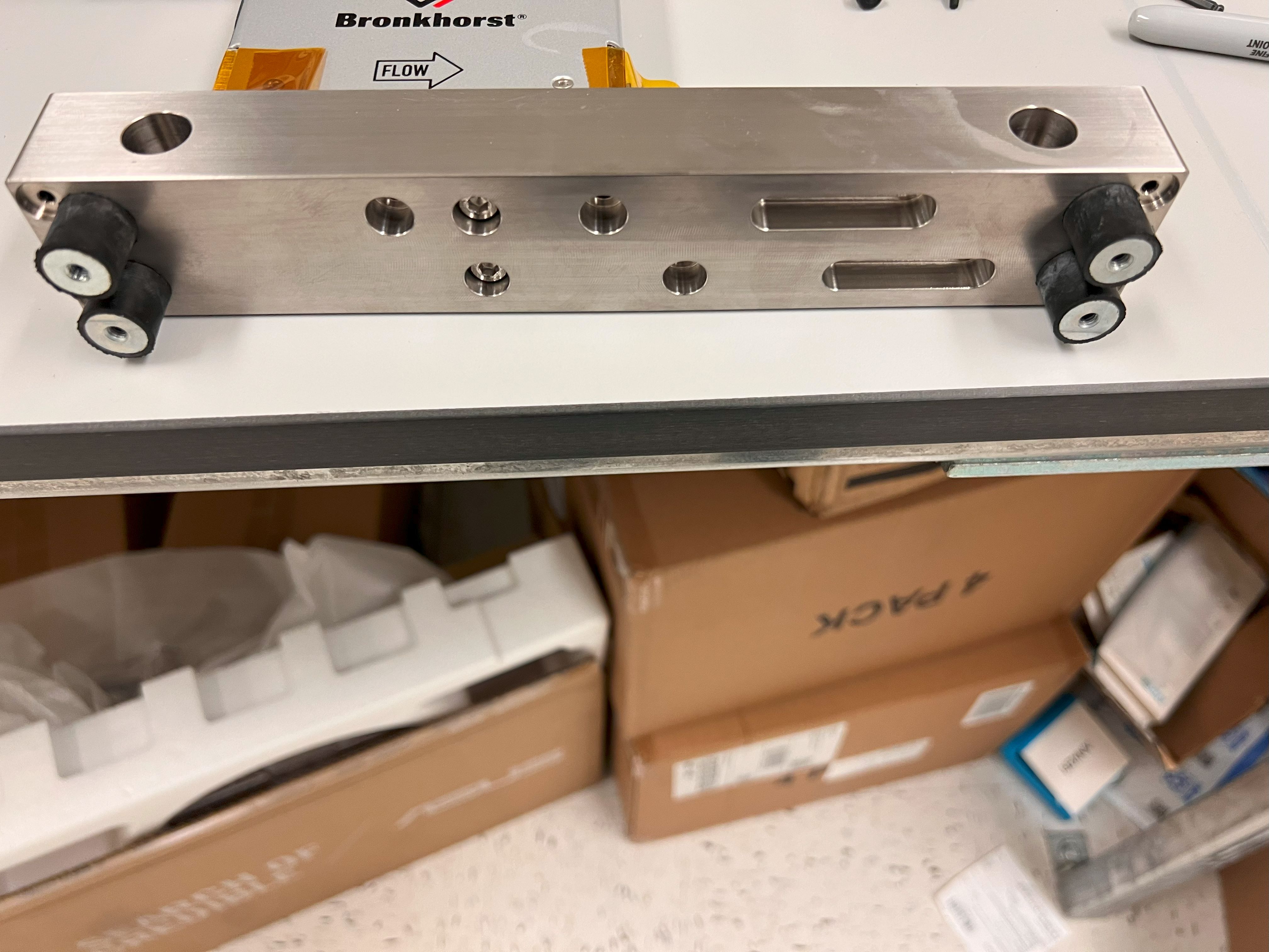
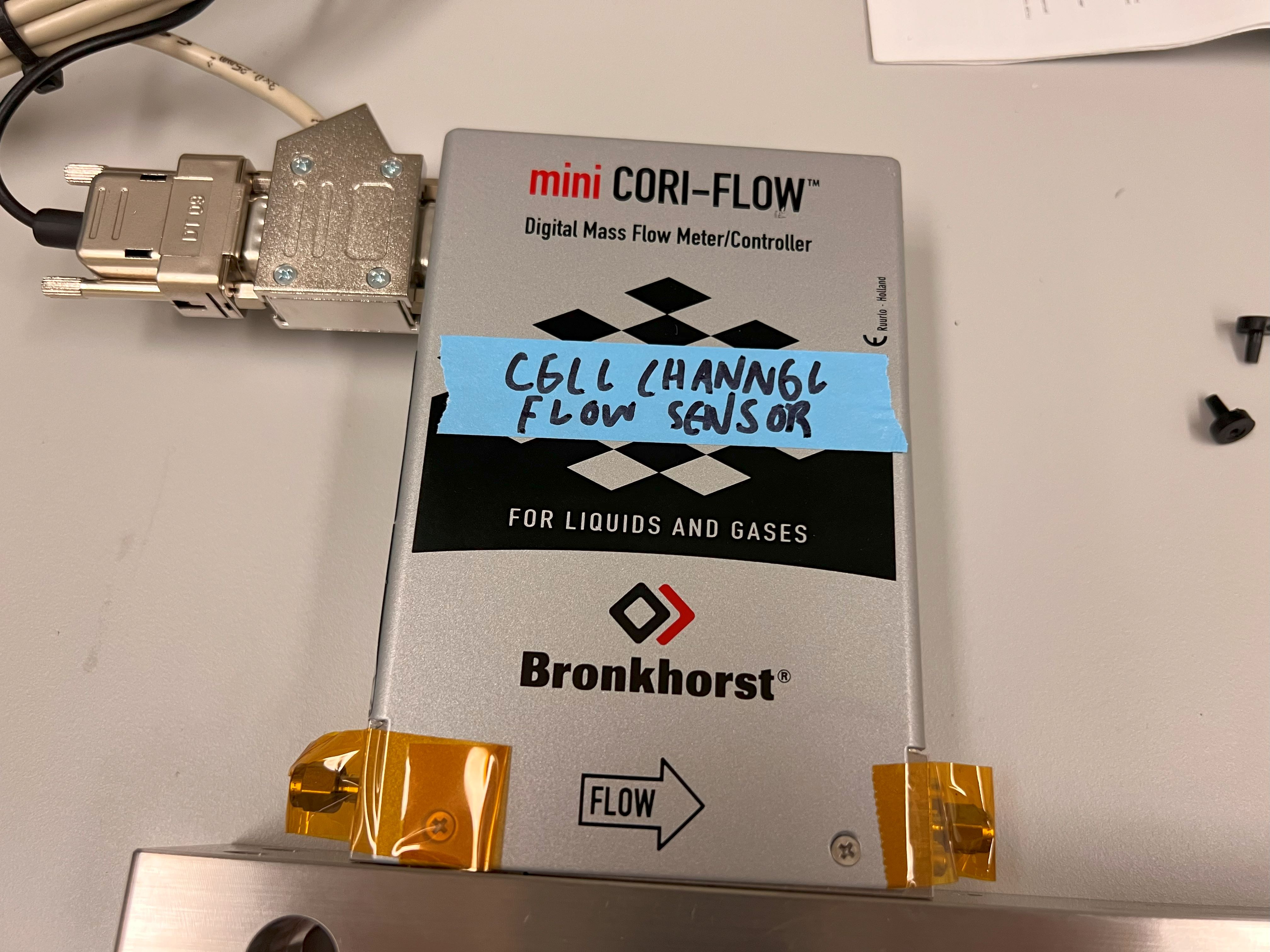
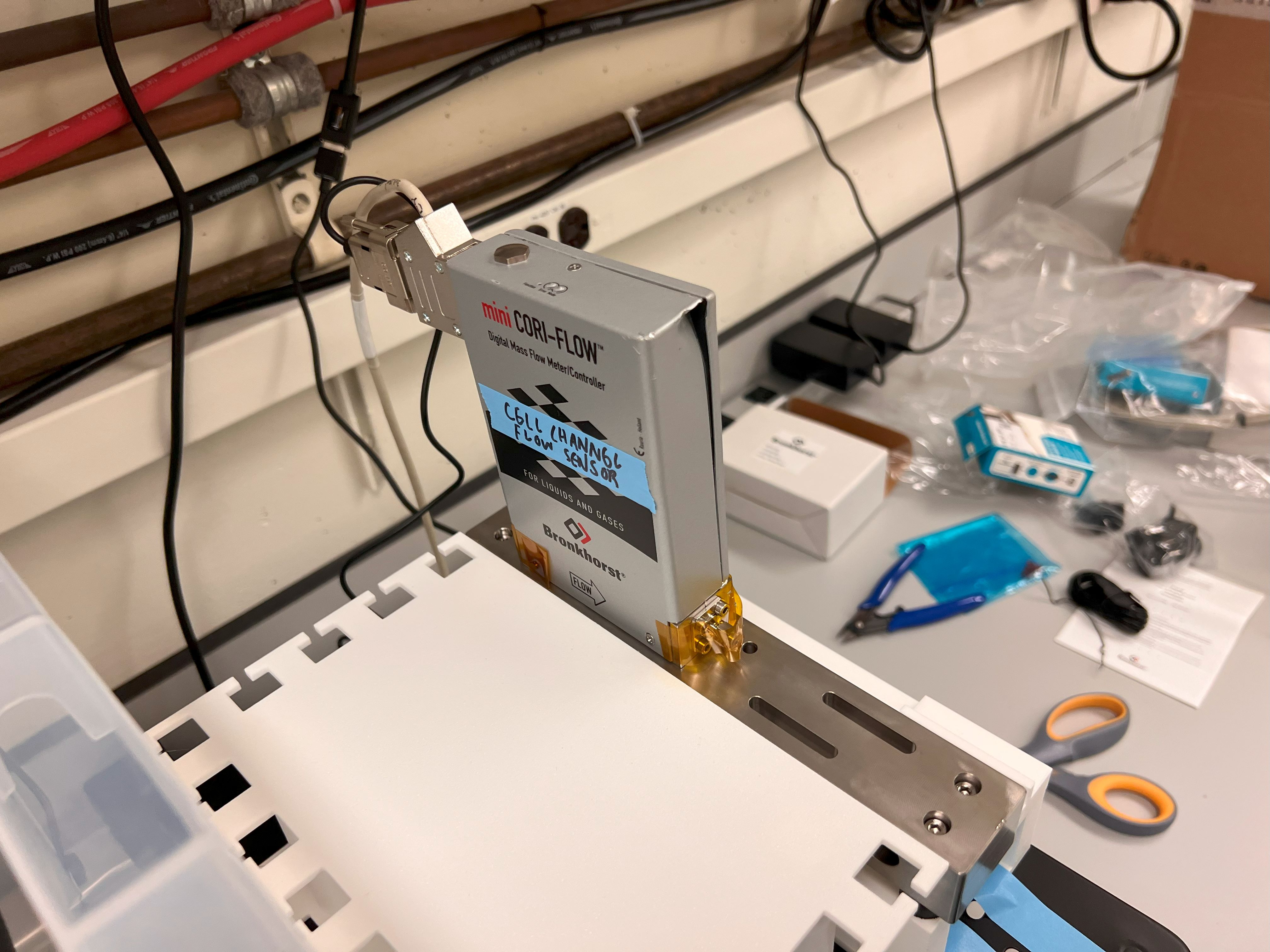
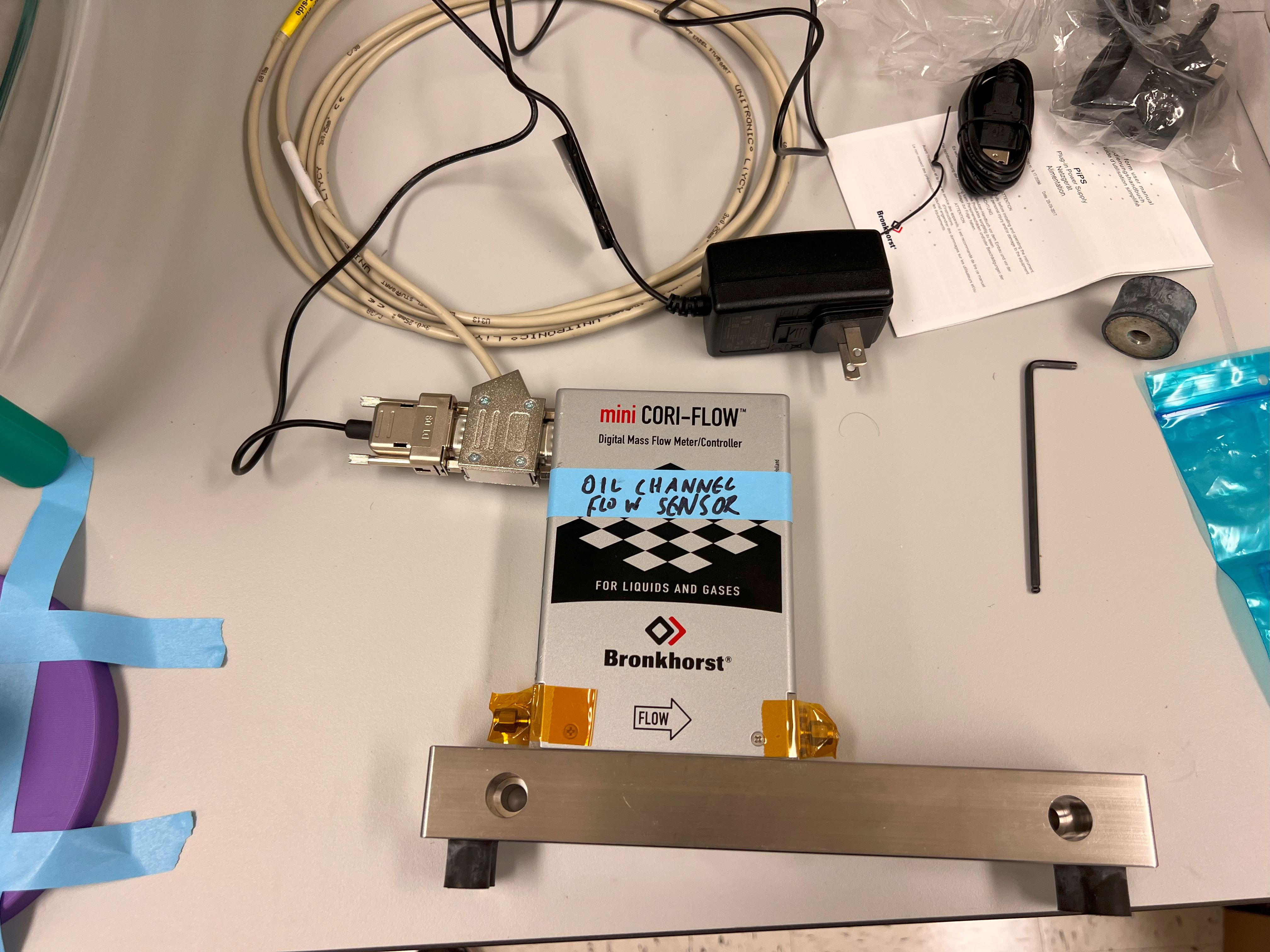
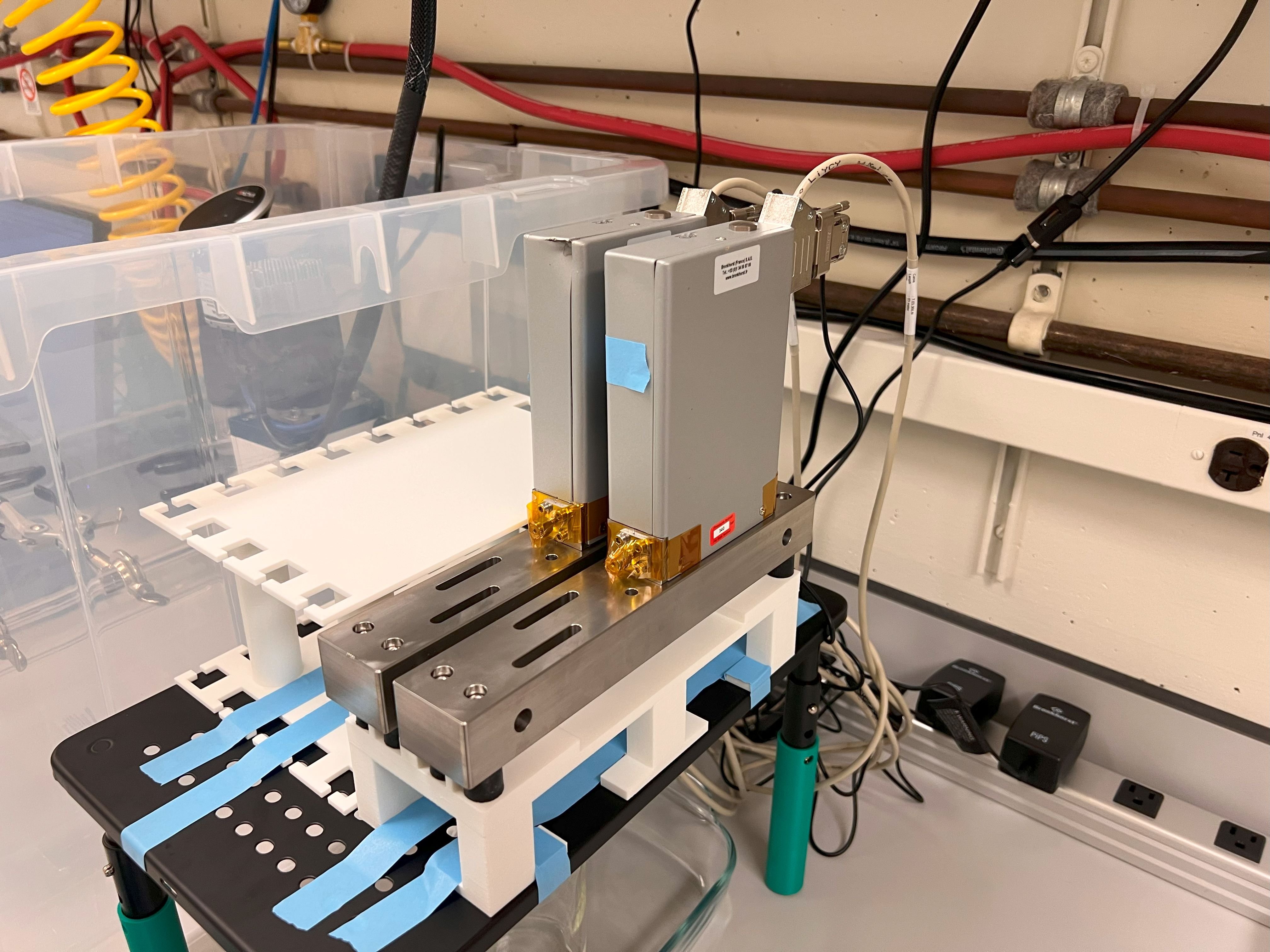
    • You will also need a Holders for your Cell and Oil Channel Flow Sensors.
  • We also made an Iphone Holder to help record videos and photos of the microfluidic chip. The 3MF and CAD files for that can be found here.
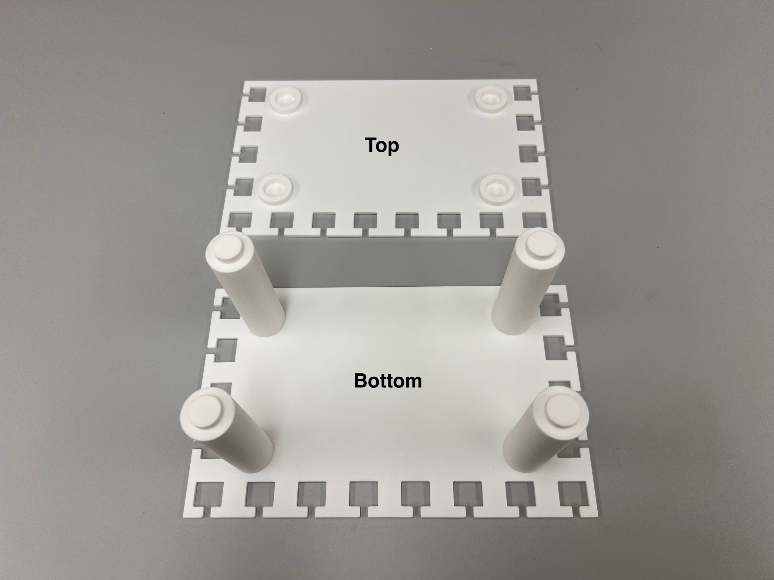
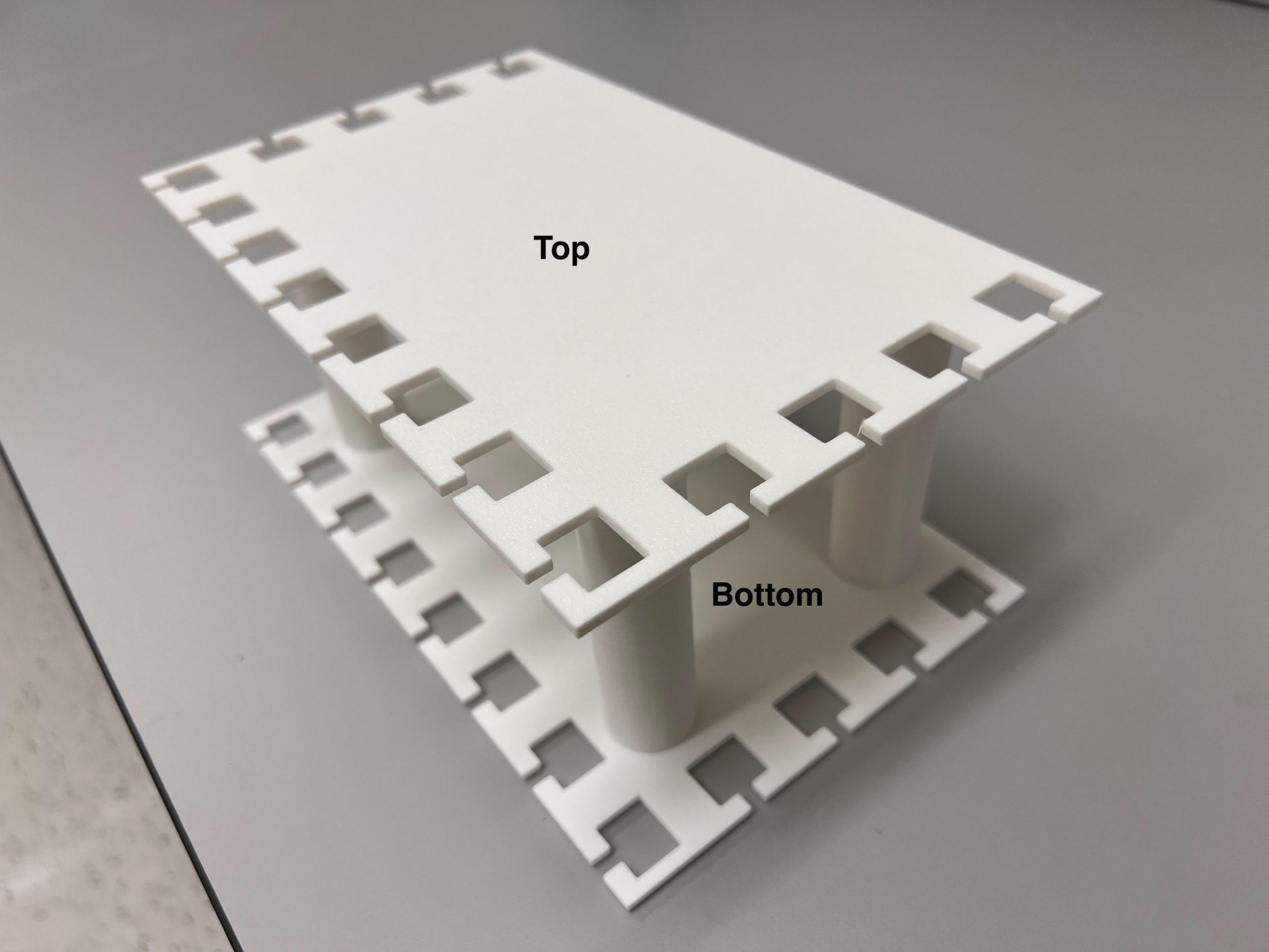
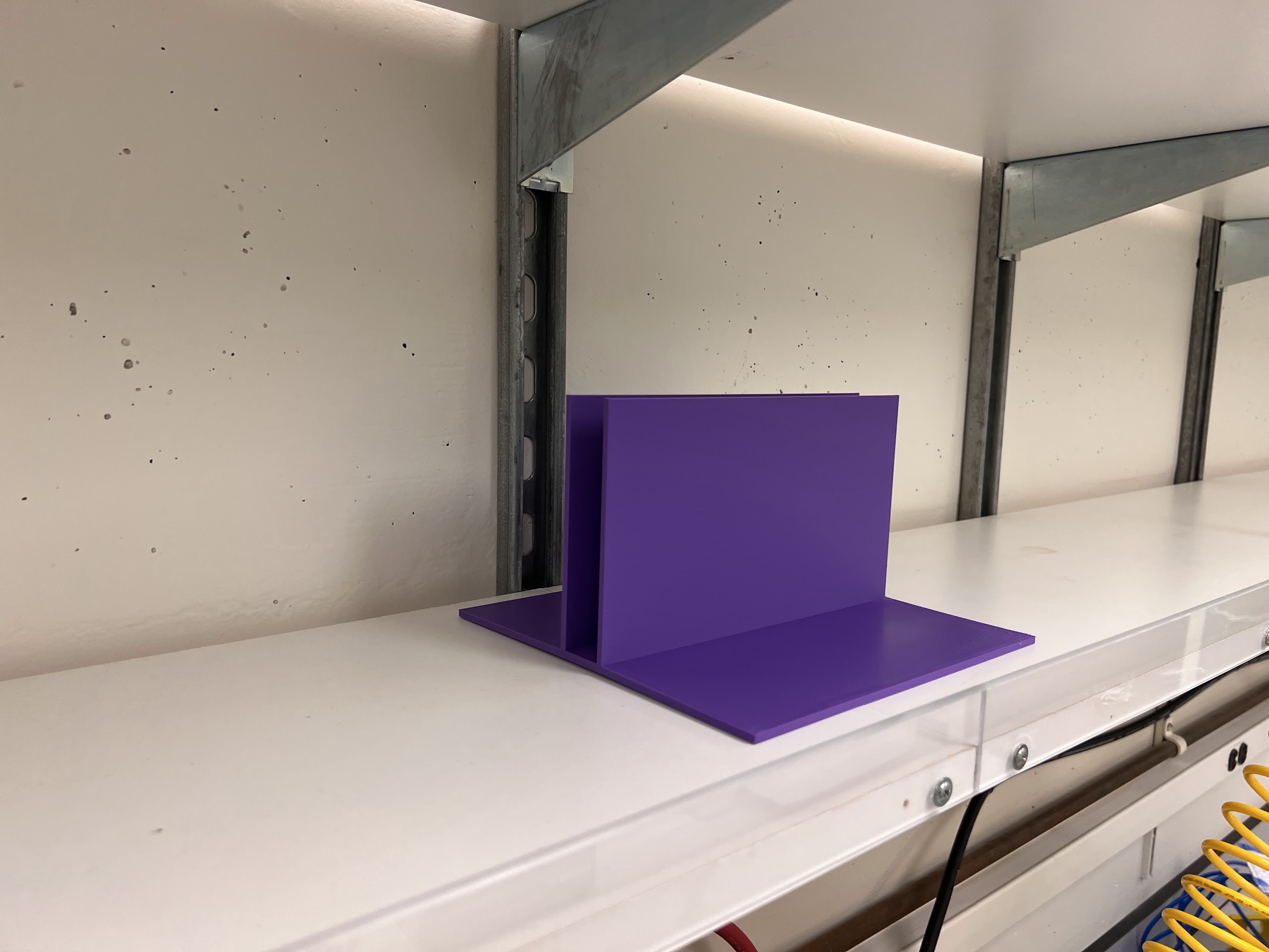
  • You will also need to print two Valve Holders.
    • Each Valve Holder has two parts. The Top and Bottom Parts.
    • You can simply push the Bottom and Top together for a snap fit. This will make one complete valve holder.
    • You can find the 3MF and CAD files for Valve Holders here.
    • Use White Colored PLA for these Holders.
  • We recommend getting a 3D Printing Accessories Kit if you haven't purchased one already.
    • Its extremely helpful in removing supports and cleaning up the print.

Ordering Expensive components and Components with long lead times:

Expensive Components:

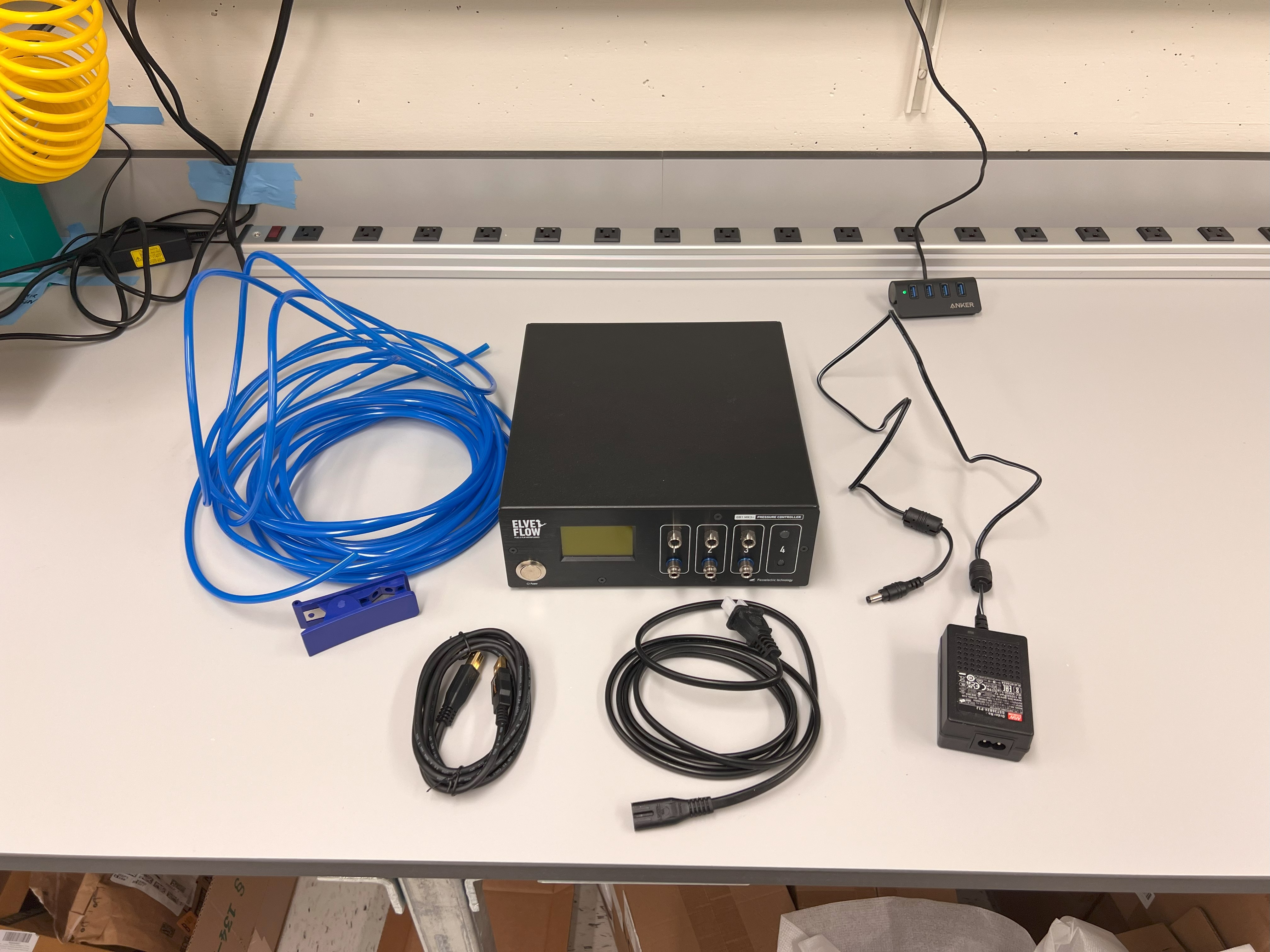
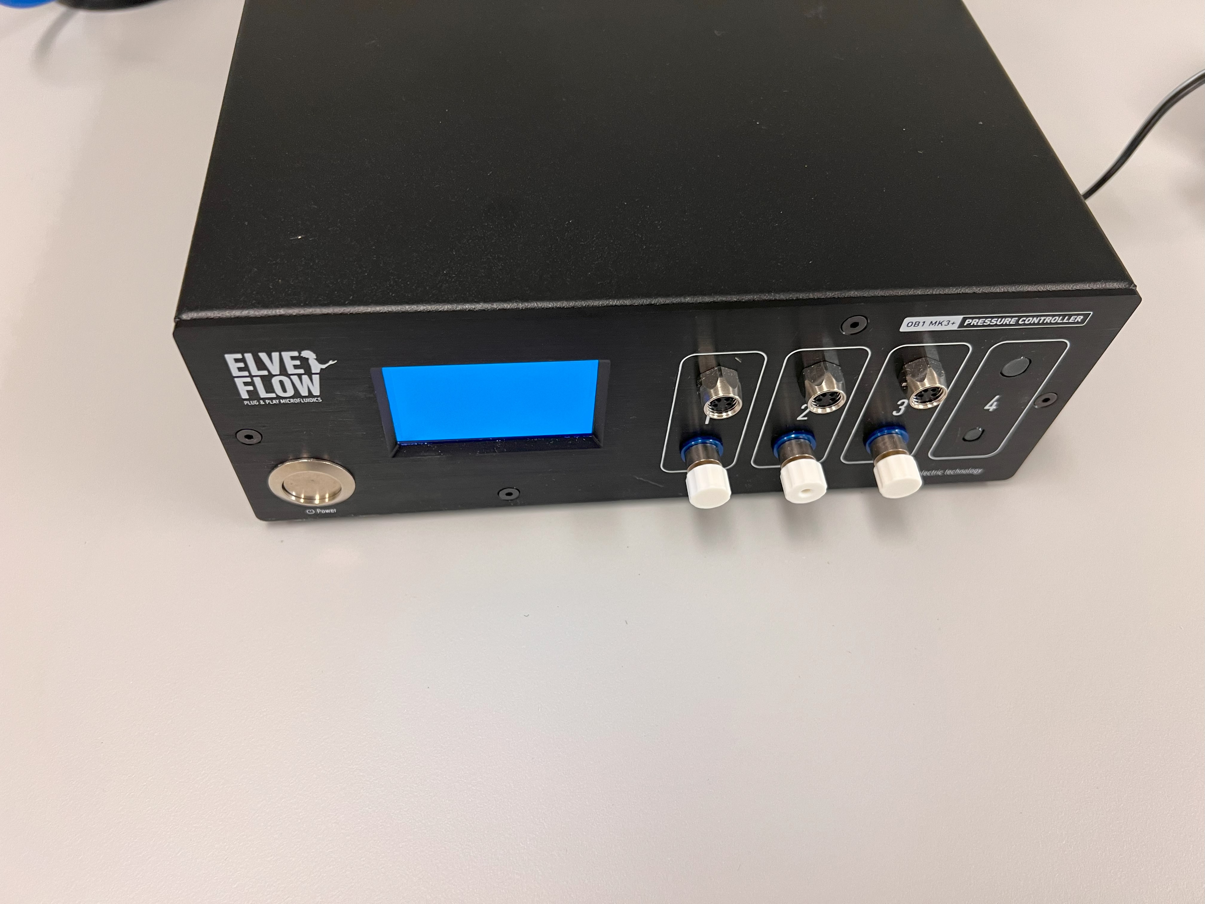
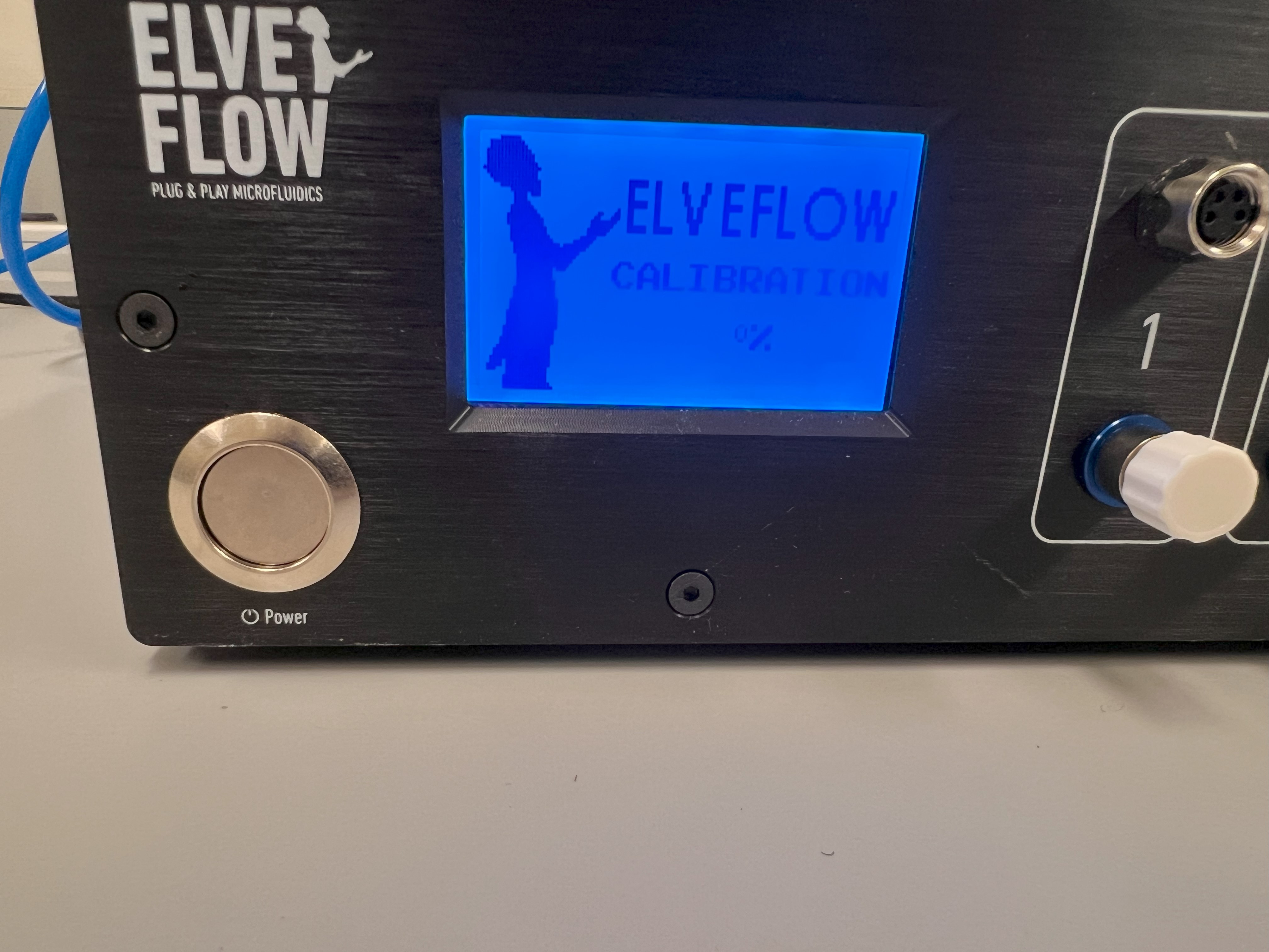
  • We ordered the OB1 Flow Controller from Elveflow. The Configuration was as follows:
    • 3 Channels only. All Channels were (0-2000mBar)
    • You will also need an AC Power Cord for North American Outlets
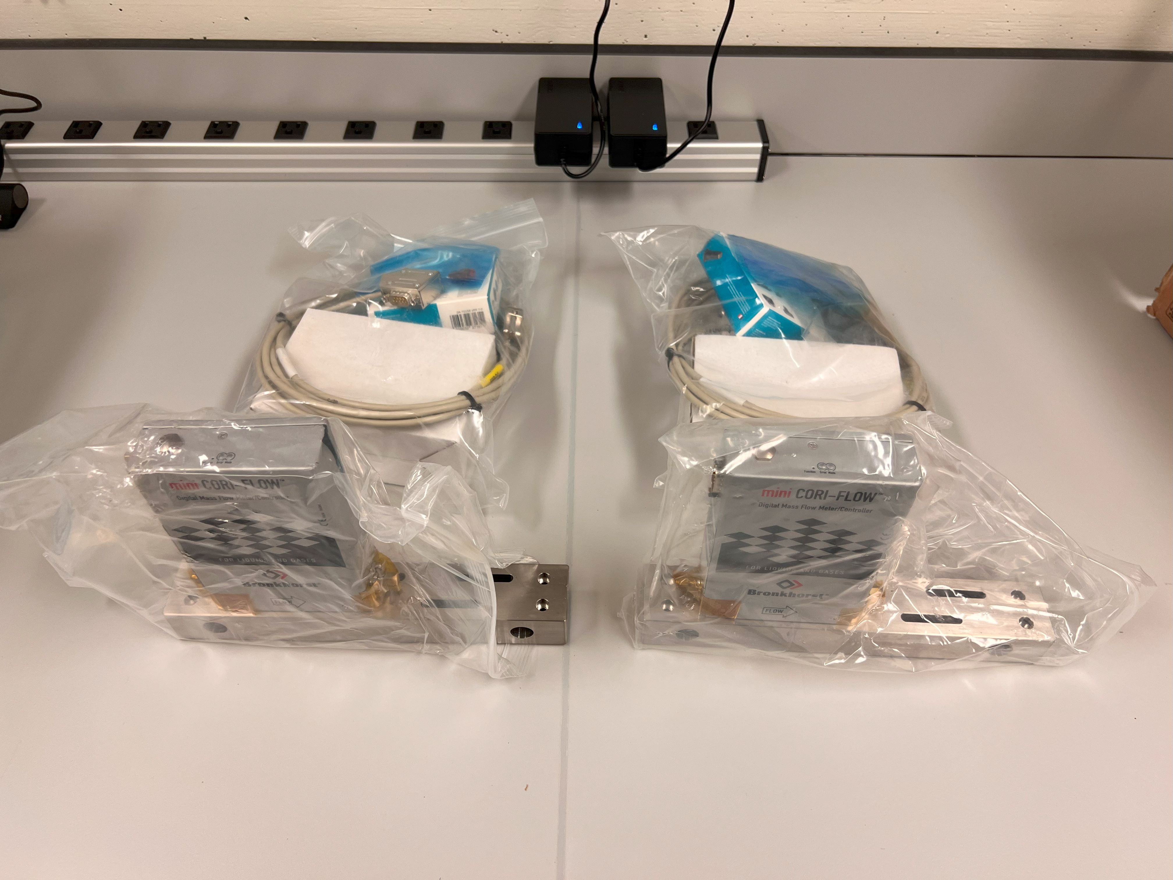
  • We ordered two Coriolis Flow Sensors from Elveflow:
    • BFS 1 Configuration. 2% Accuracy.
  • Elveflow will try to sell you more features, components and additional kits. Politely refuse to buy anything else.
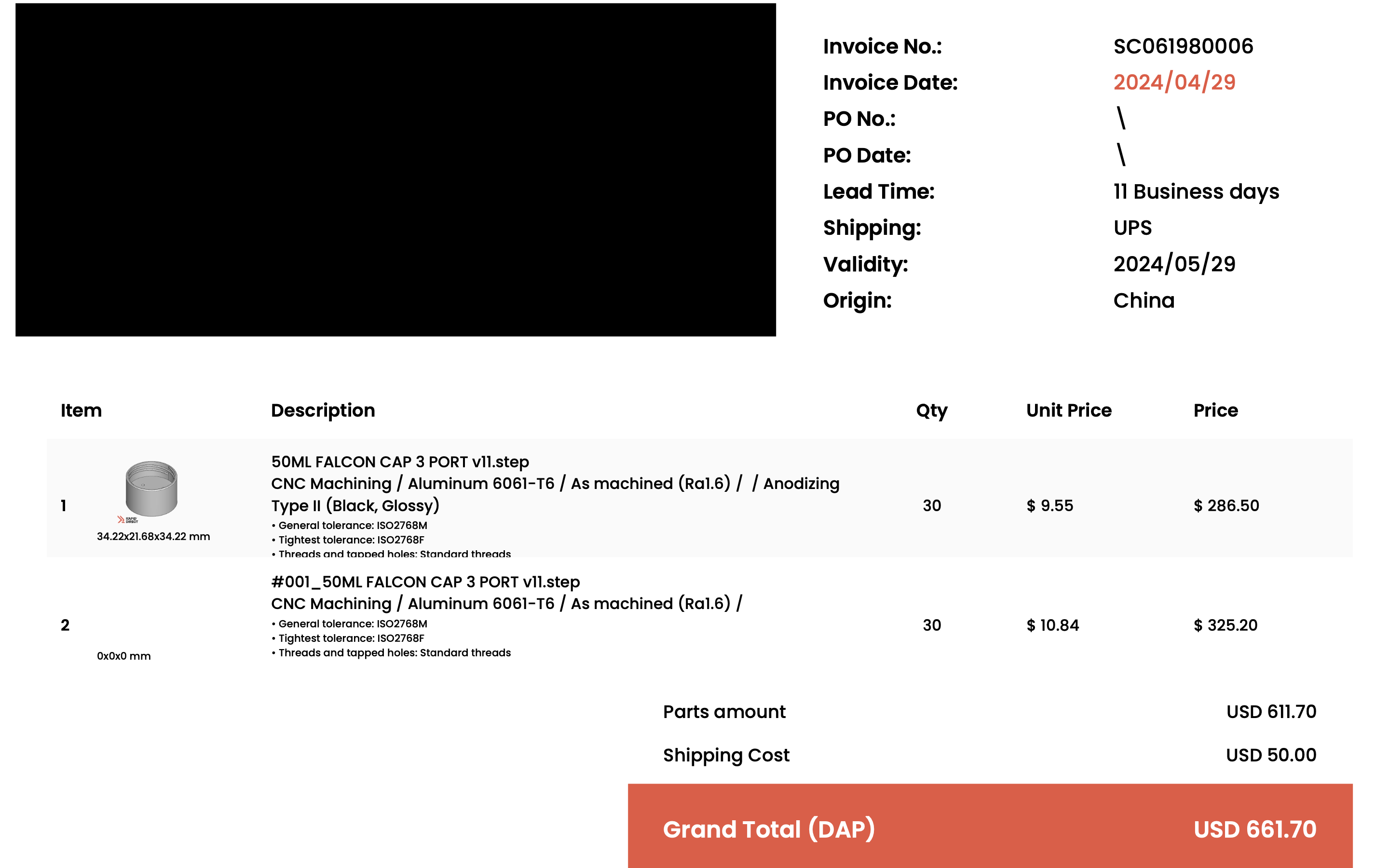
    • I've included a copy of the Invoice page. You can see how much we paid for these components and what exact items we ordered.
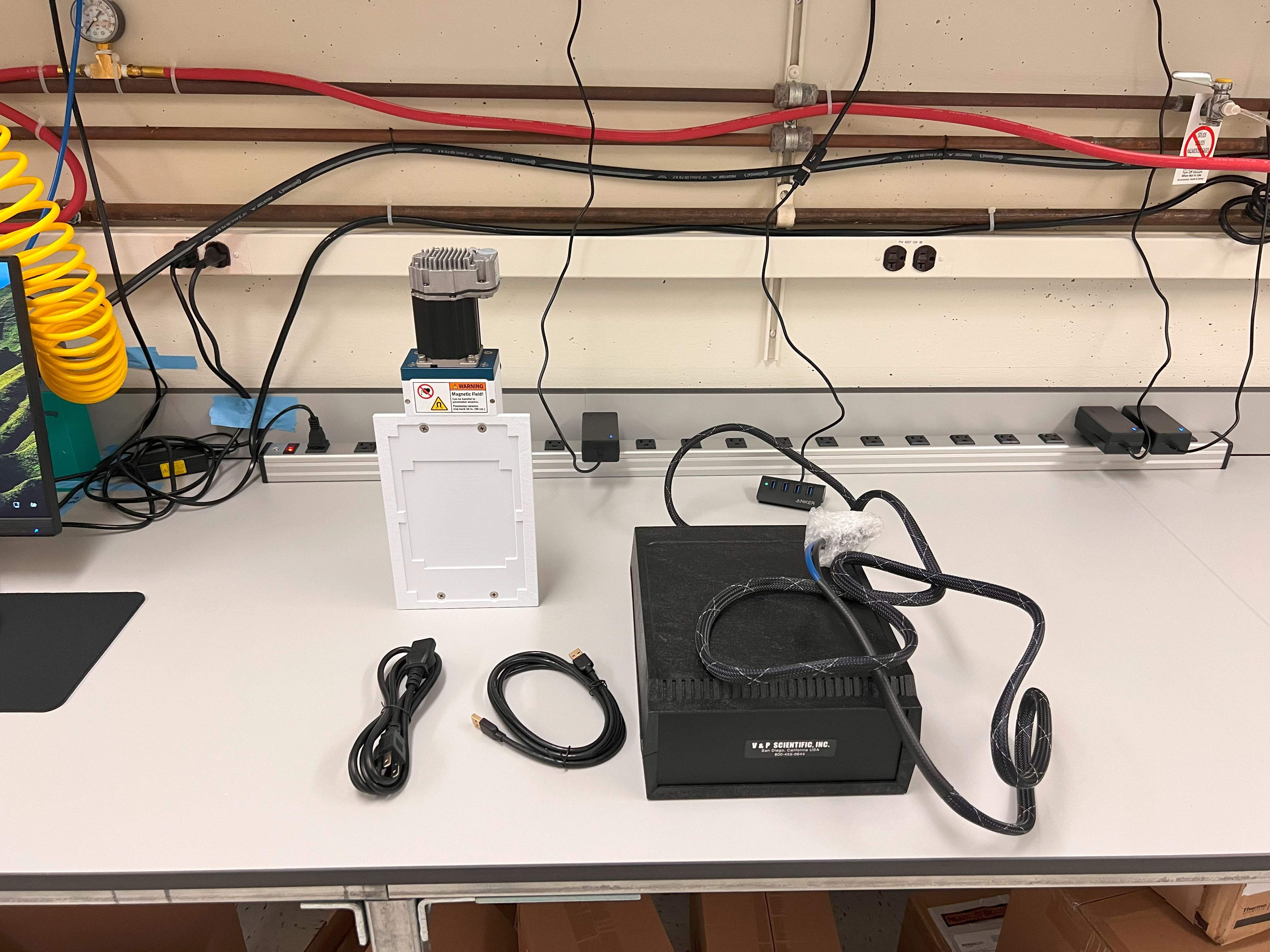
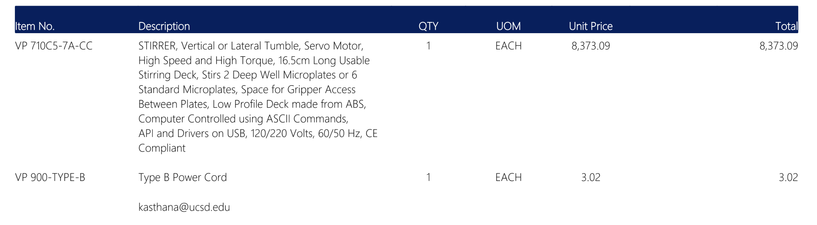
  • We ordered the VP 710C5-7A-CC Vertical Computer Controlled Stirrer from V&P Scientific. Here is a screenshot of the Invoice from May 2024.
  • We will strive to provide cheaper DIY versions or replacements for these expensive components in future versions of ChronoSeq.
    • Help and contributions from community members is appreciated. Create a merge request when you are ready.

Long Lead Time Components:

  • We ordered two VX-200 Vortex Mixers
  • We ordered two 50ml Heads for the VX-200 Vortex Mixers
  • We ordered a 3D Nutating Mixer.
  • We ordered the AE31 Elite 30W Trinocular Inverted Microscope

3 Port Reservoirs

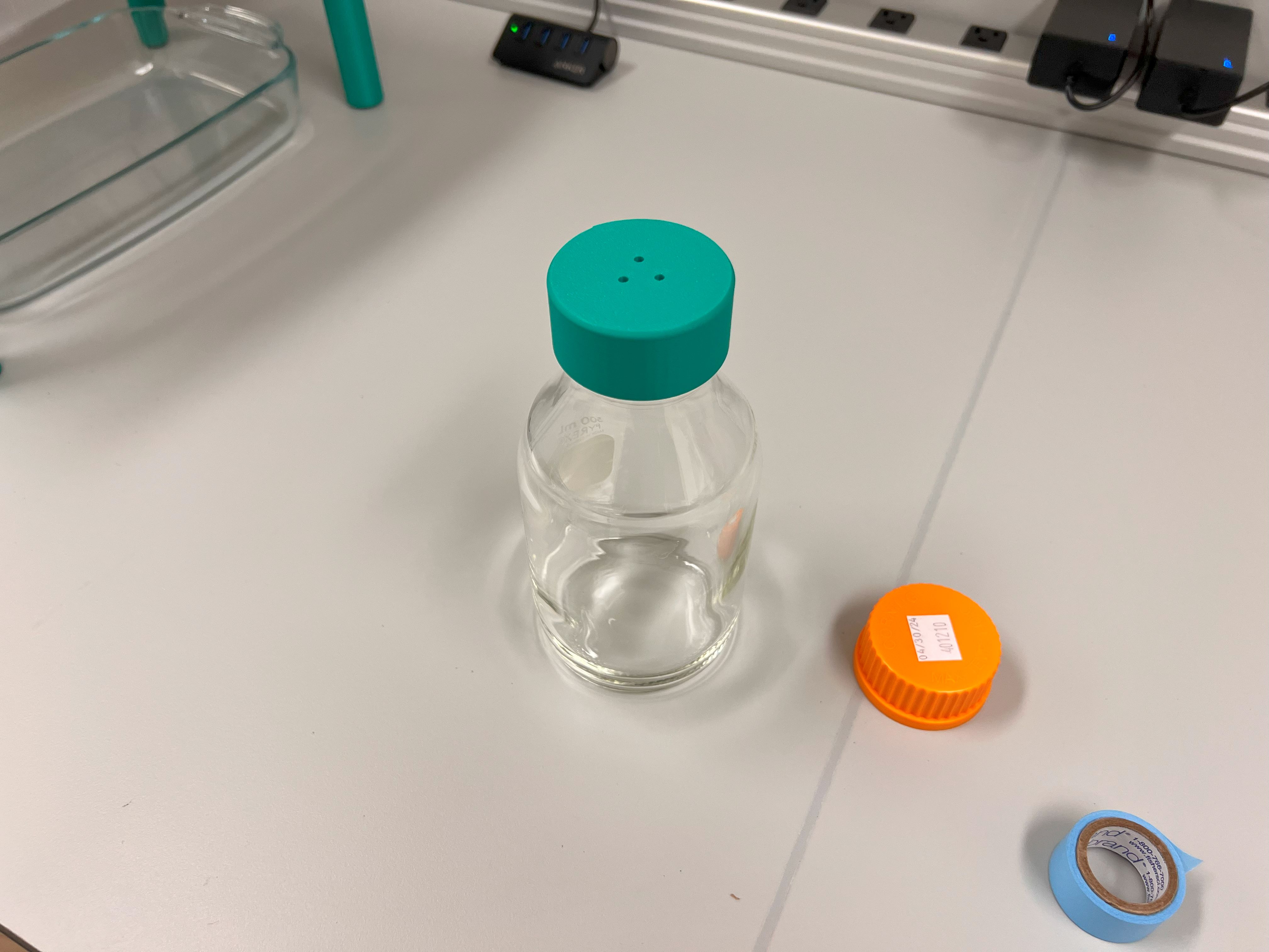
  • You will also need to have reservoir caps manufactured for the 50ml Falcon Tubes.
  • These reservoirs will contain the liquids that need to be moved through the ChronoSeq device.
  • They have been designed and tested to be gas tight.
  • They allow quick changes in pressure to be applied to the liquids stored in the reservoirs. This changes the flow rate of the liquids to also be changed.
  • The CAD Files can be found in this directory. You can read the manufacturing instructions here.
  • We had these parts manufactured by RapidDirect.
    • Our Order number was SC061980006.
    • Most likely they still have the CAD/CAM files from this project. So they should be able to quickly manufacture these parts for you.
    • Just ask them to make the Black Anodized Version for you. You don't need the As-Machined version.
    • If they refuse to do this, just follow the Manufacturing instructions linked above.
    • Here is a screenshot of the invoice:

Manufacturing the Microfluidic Chips:

  • We used SU-8 Photolithography followed by PDMS Molding for manufacturing the Microfluidic Chips.
  • We then plasma bonded these Microfluidic Chips to 75mm Glass Slides.
  • See the protocols below on how there were manufactured using the Core Facilities at UCSD:
    • Protocol for Making an SU-8 Mold for your Chips
    • Protocol for PDMS Molding
    • Protocol for Chip Bonding to Glass
    • Protocol for Aquapel Treatment of Chips

Assembling Other Individual Components

Before getting started with this assembly protocol you need to assemble some of the individual components. Follow the instructions in the notebooks linked below before you move onto the next section:

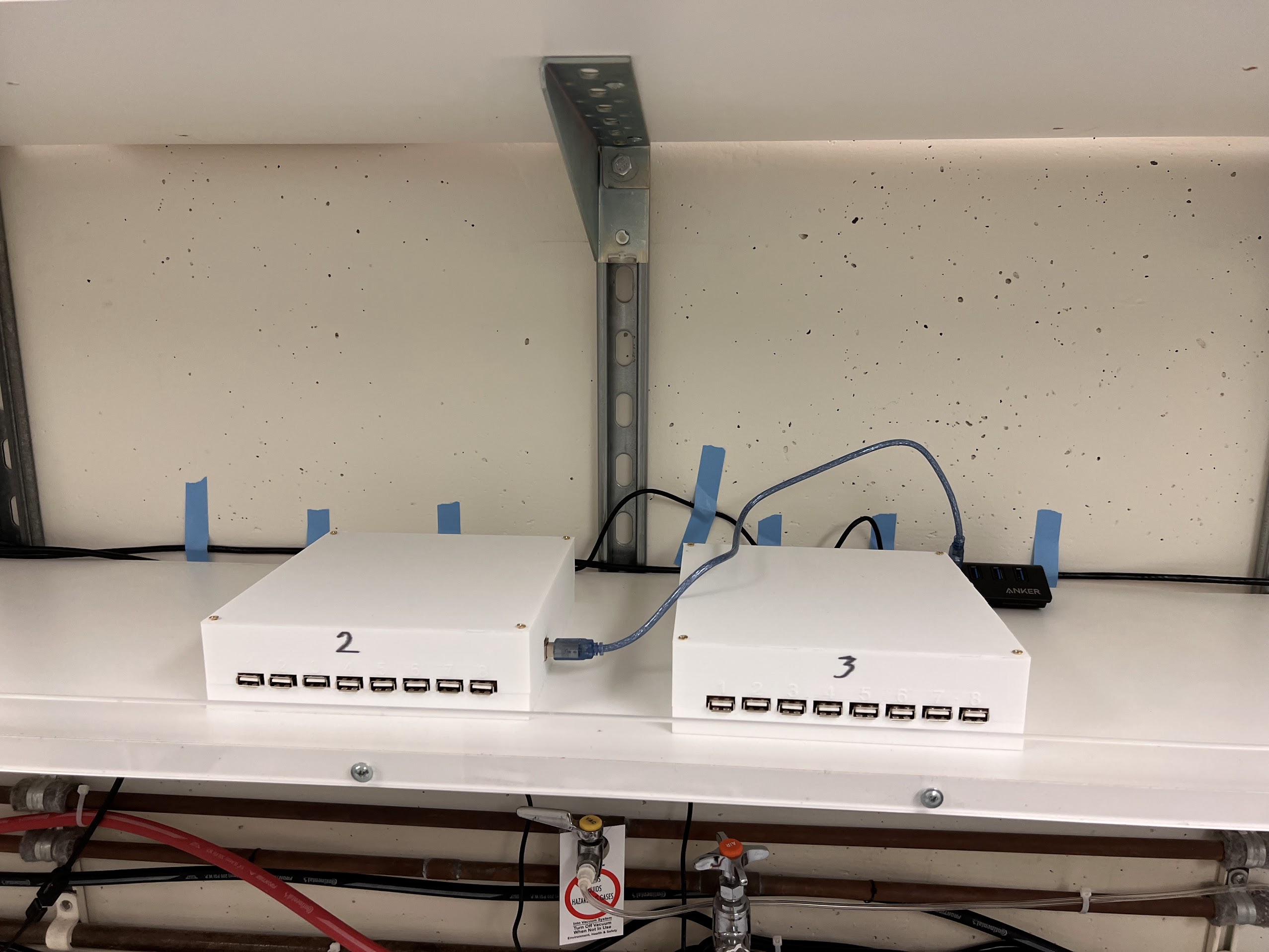
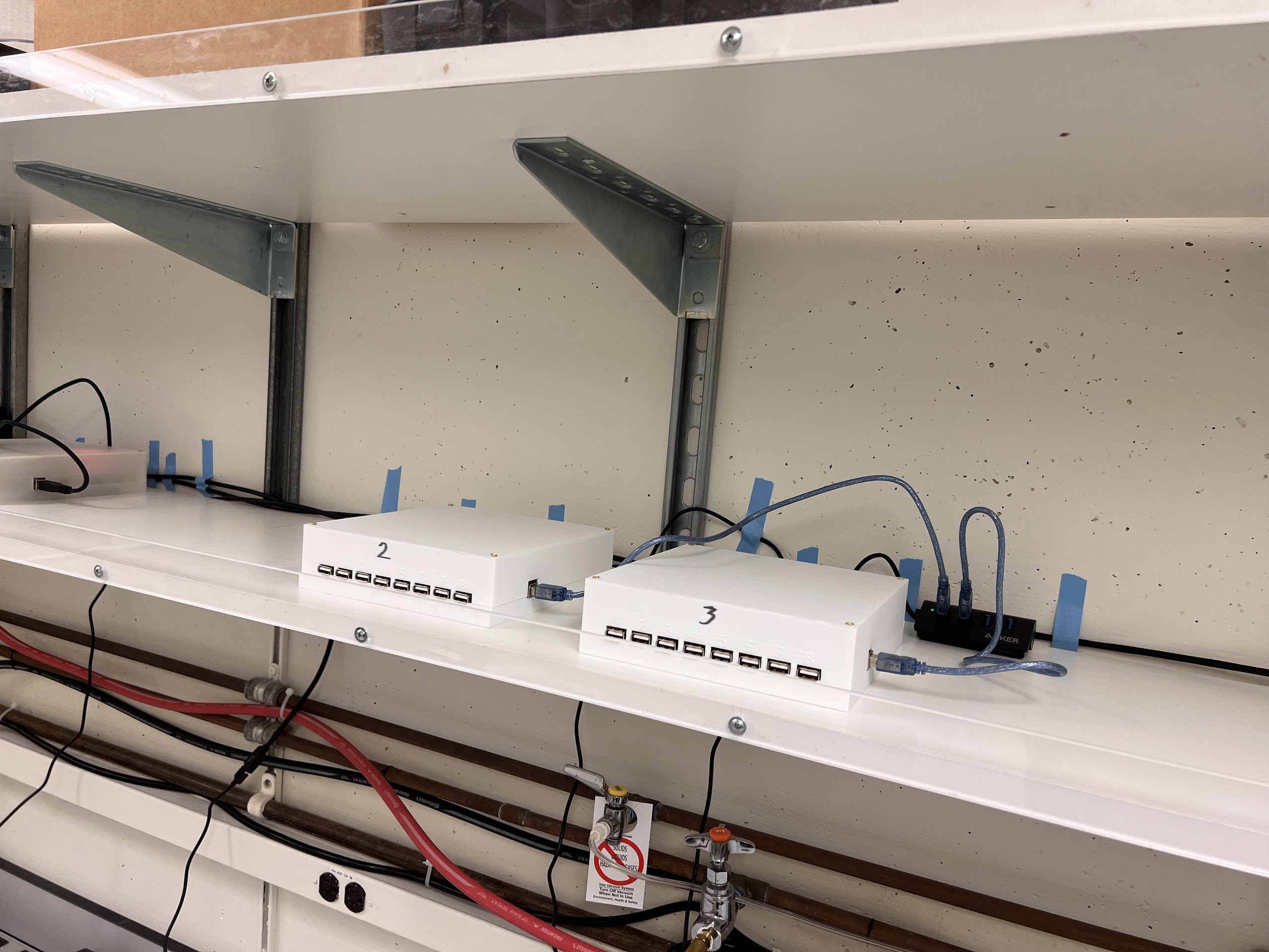
  • Assemble three valve controllers and the SMC valves
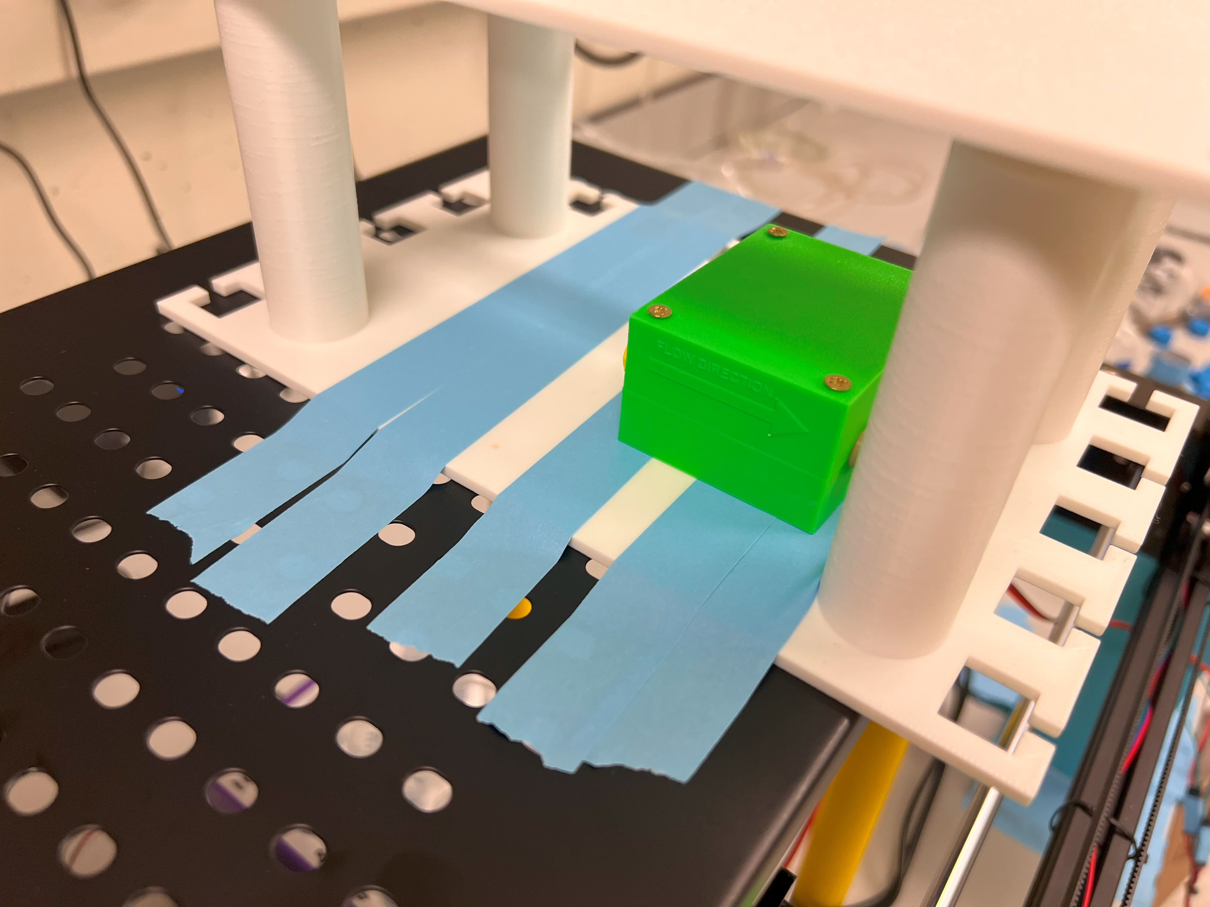
  • Assemble one Sensirion Flow sensor
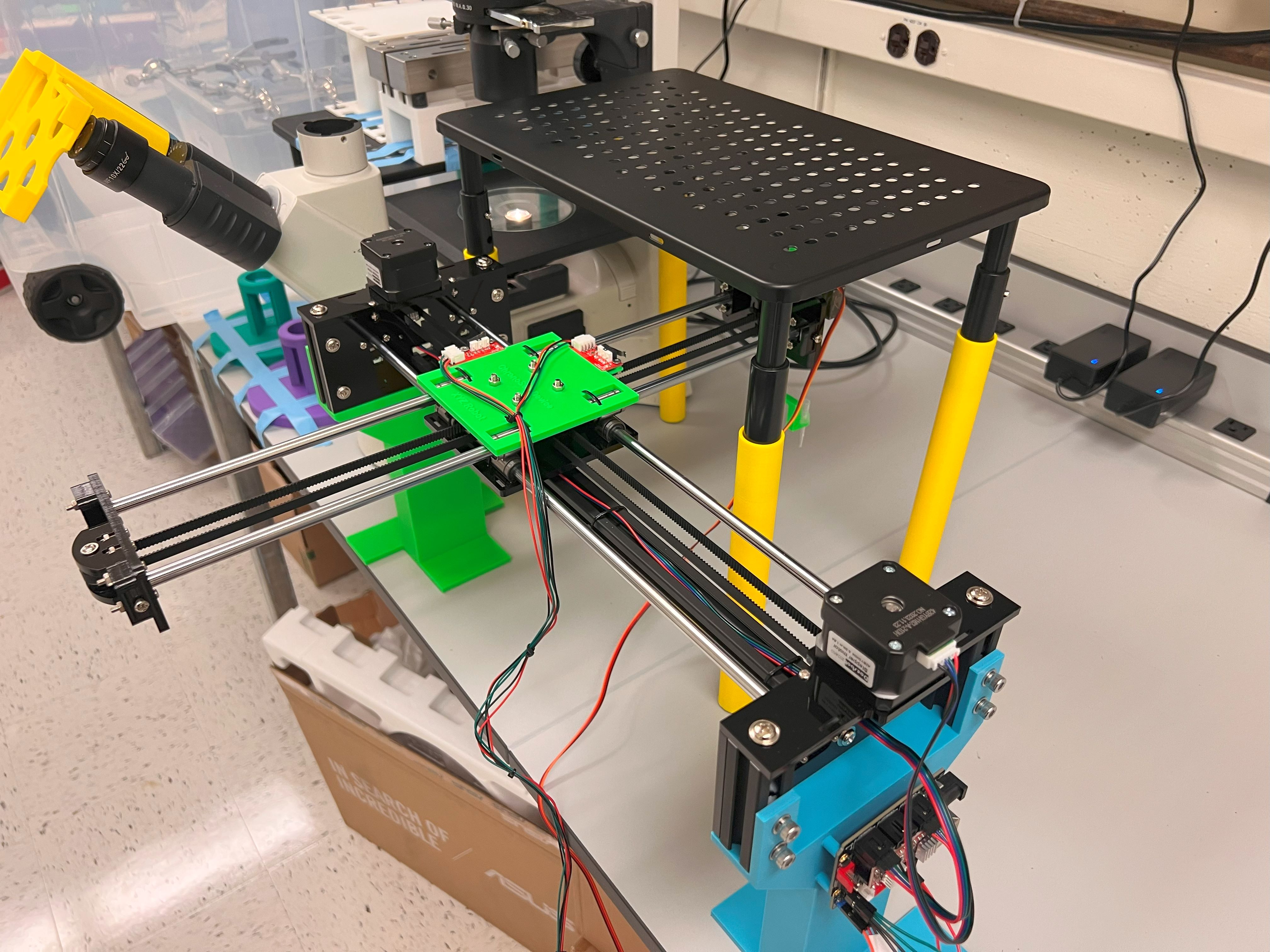
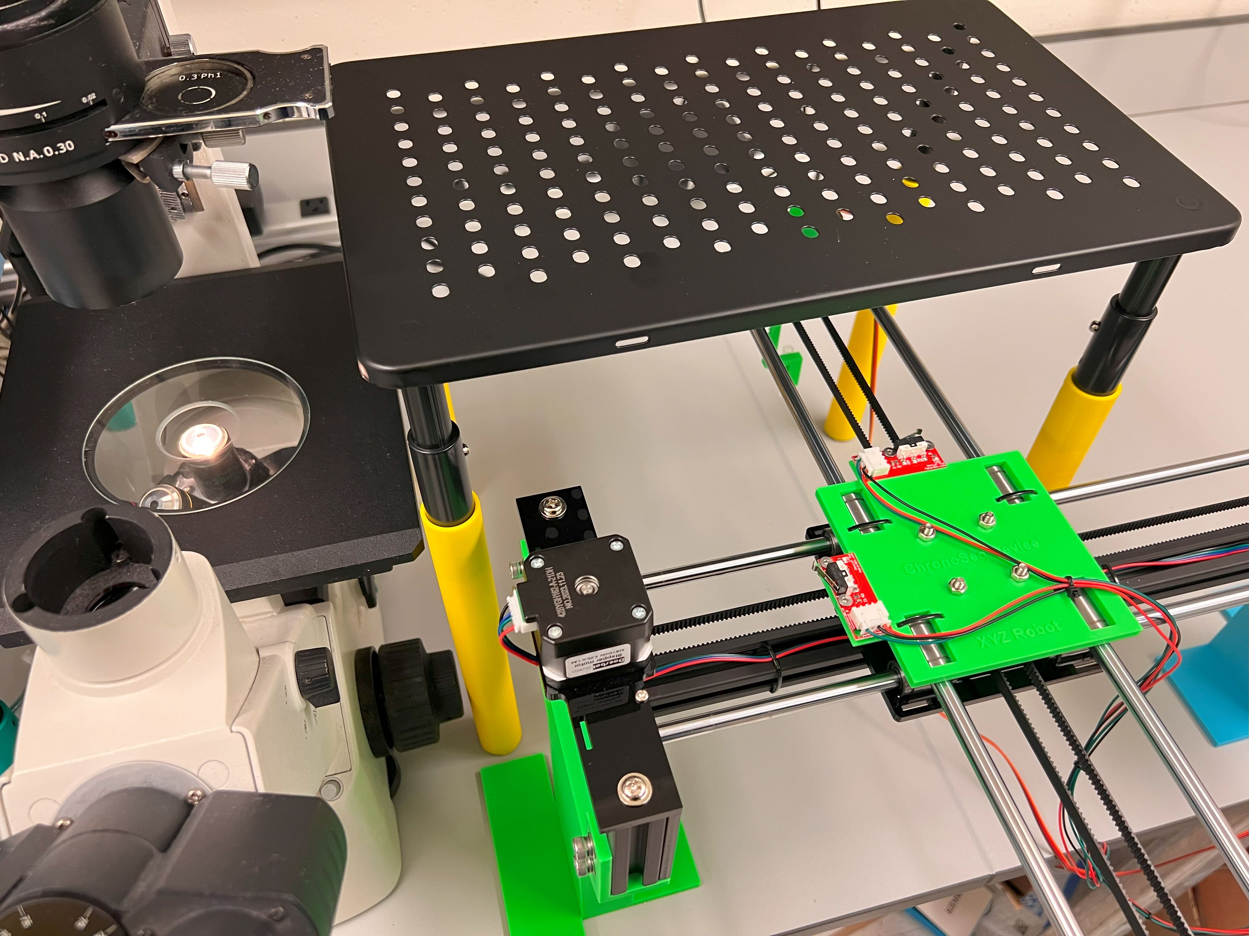
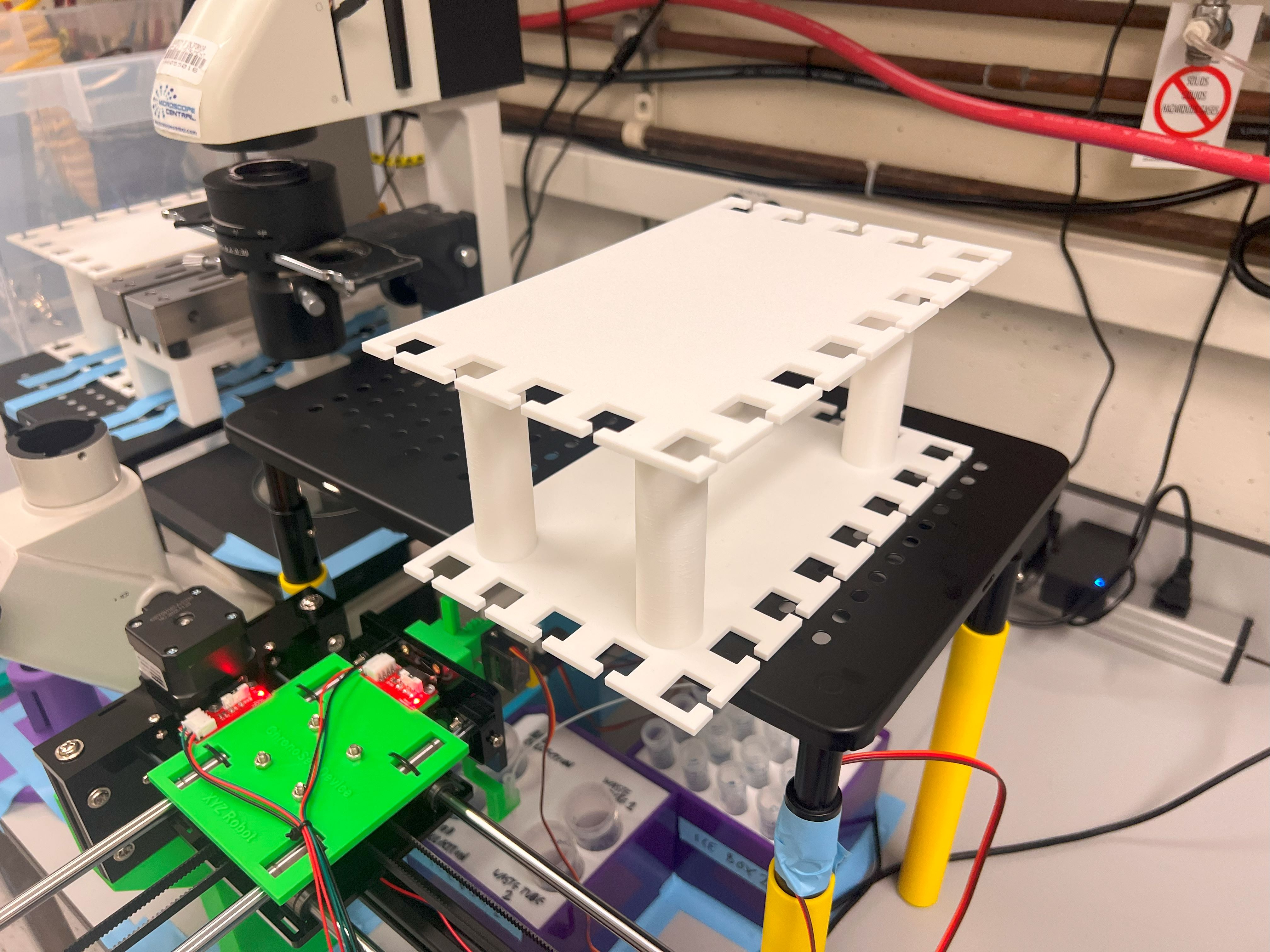
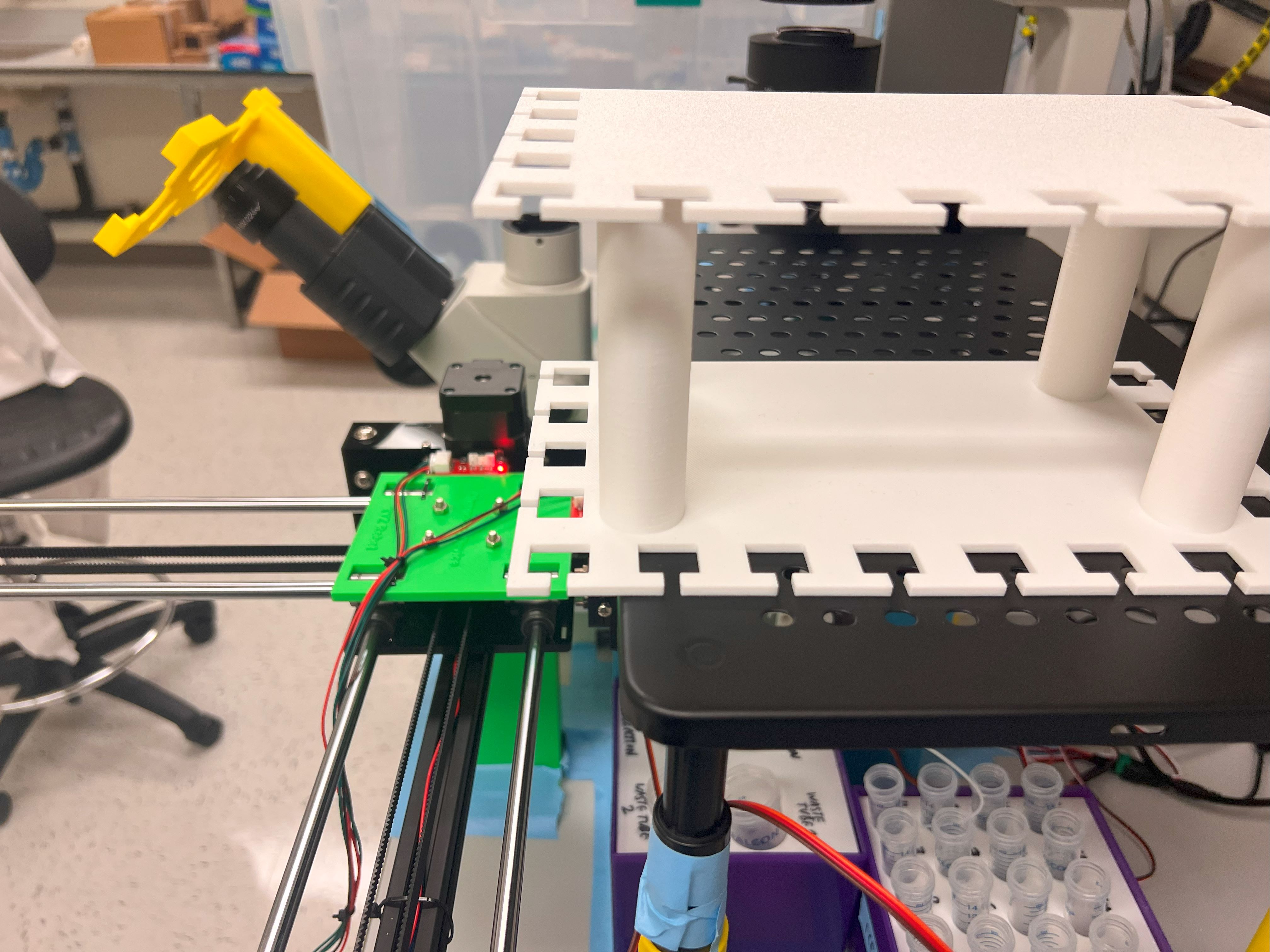
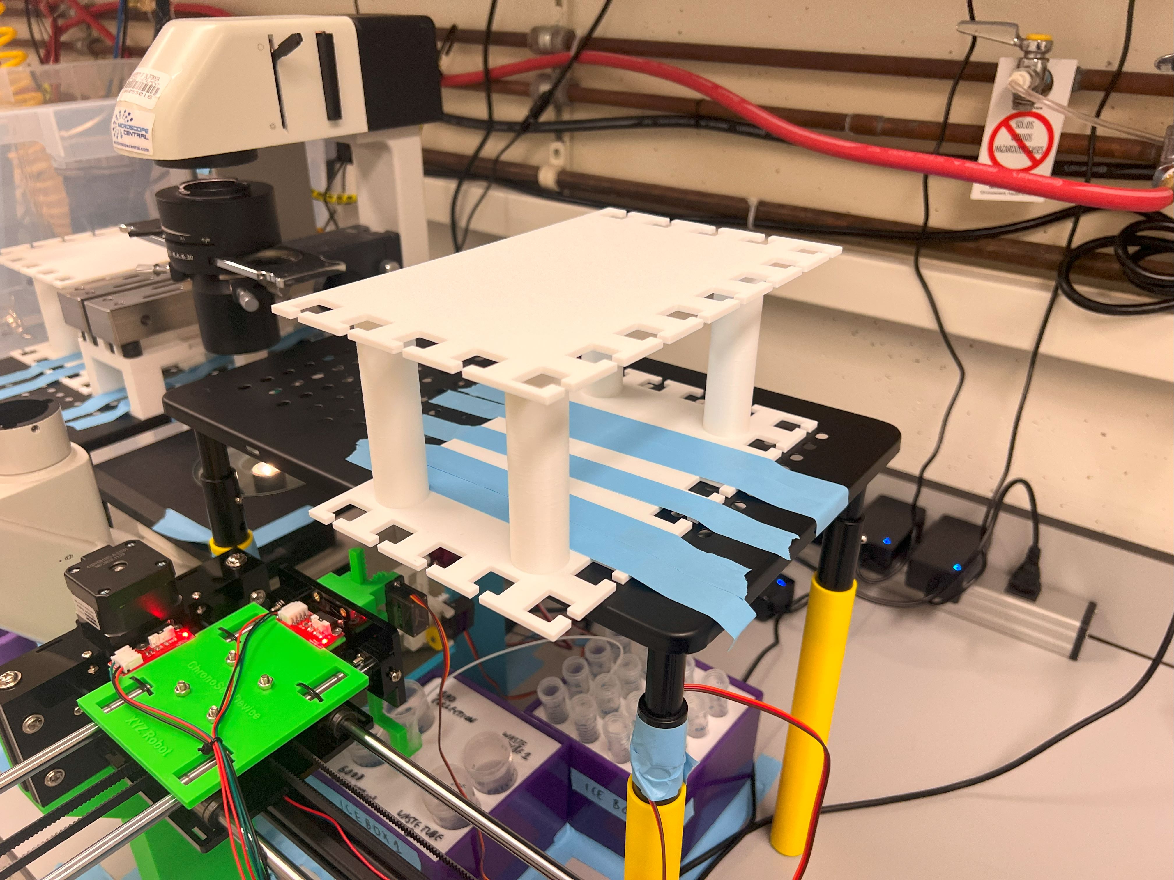
  • Assemble the XYZ Robot
  • Assemble the XY Robot and Ice Boxes
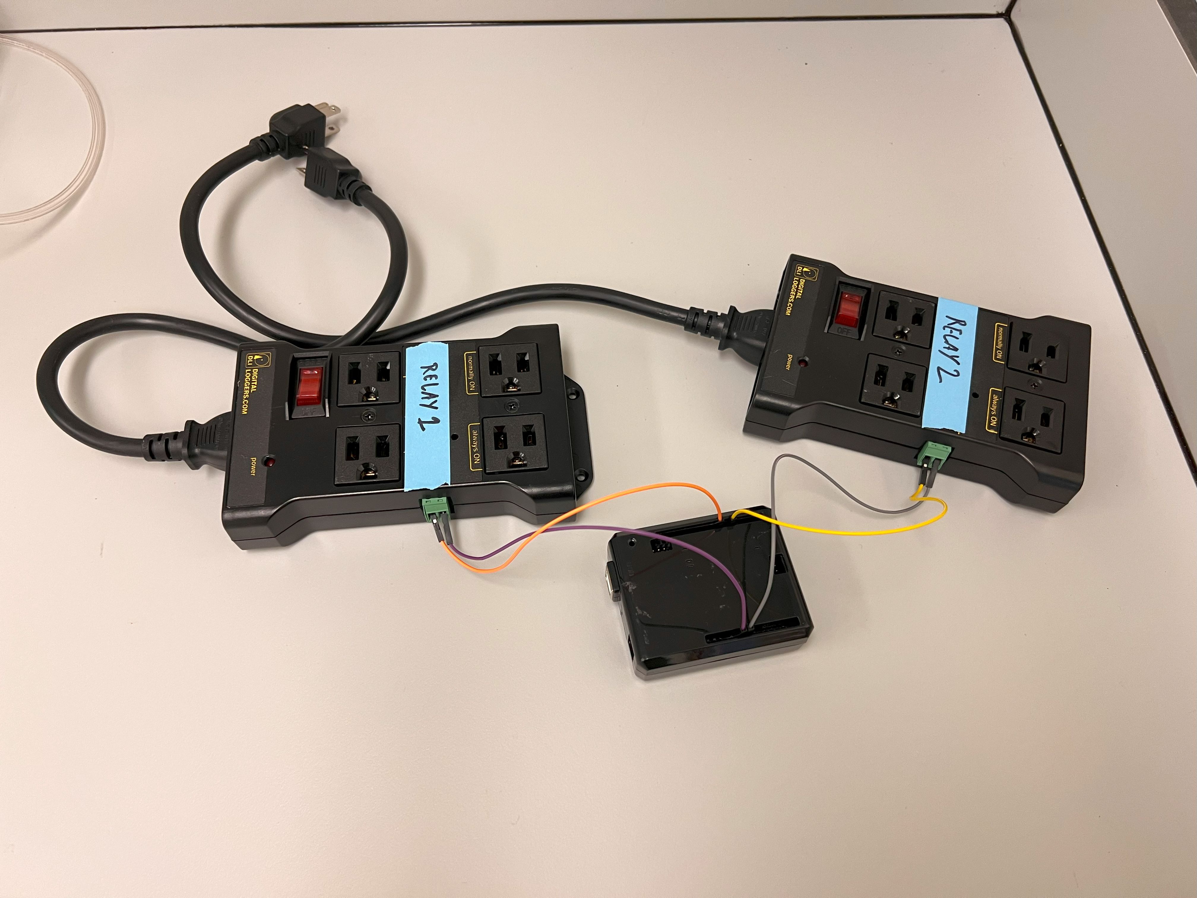
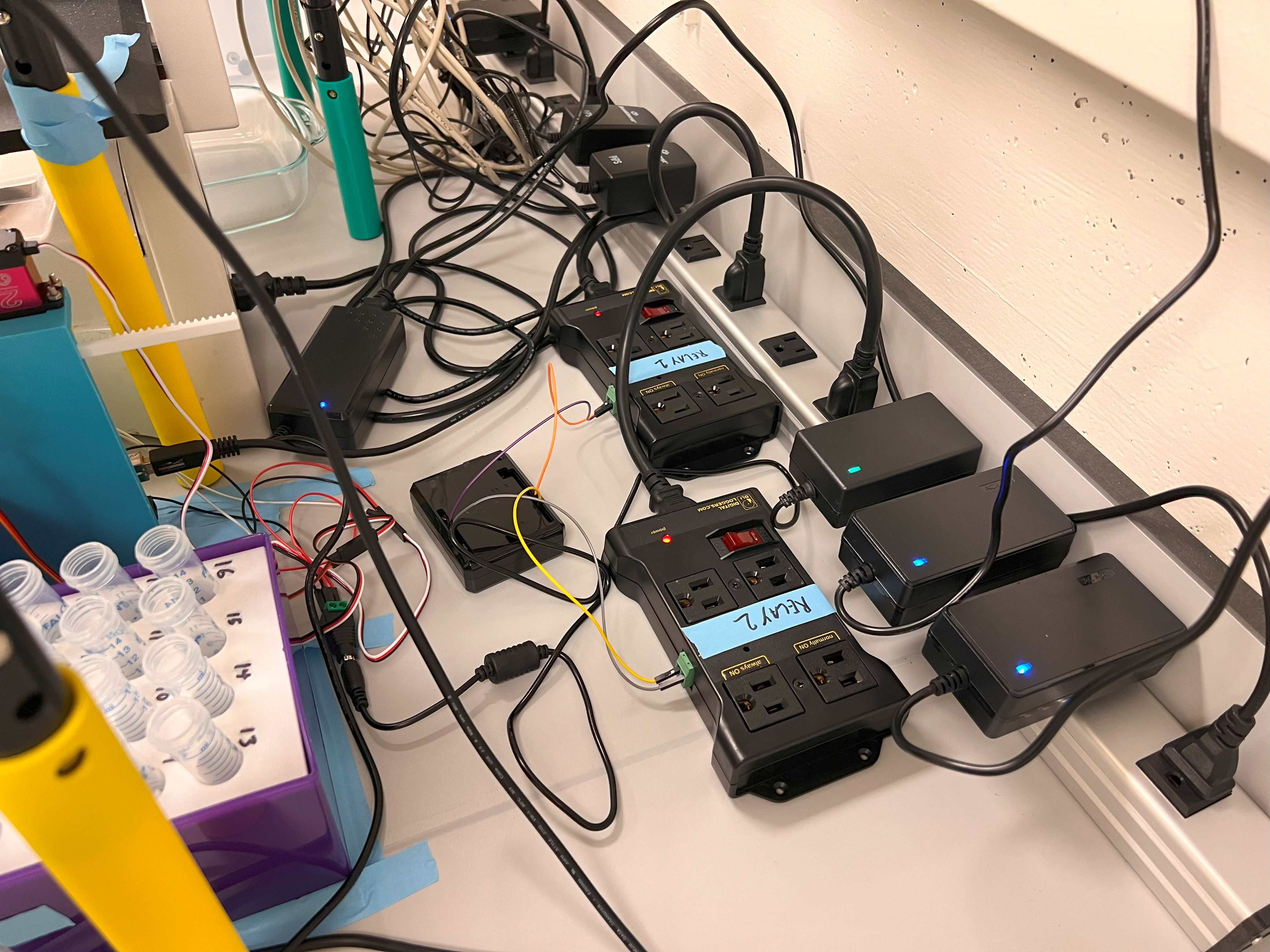
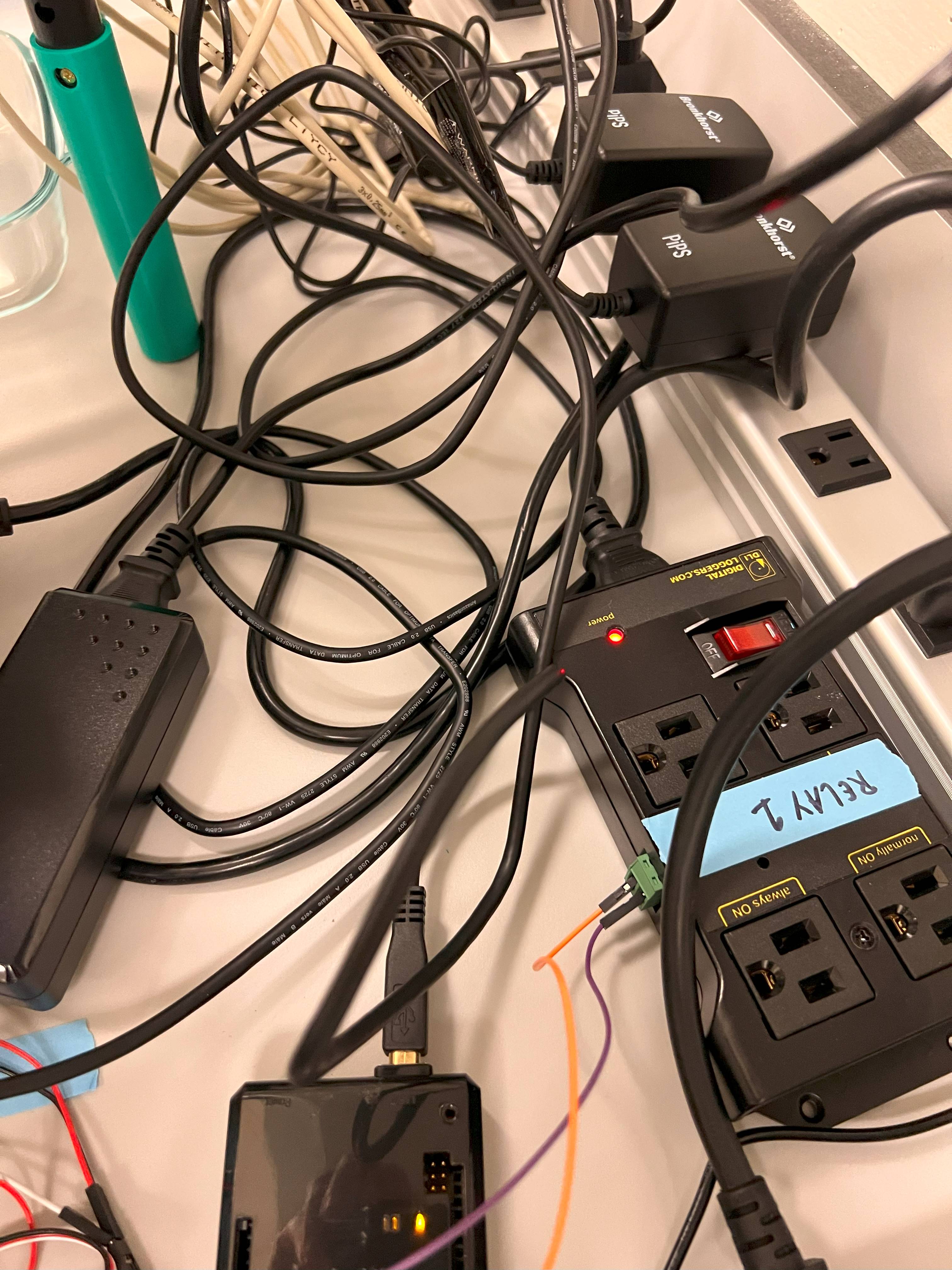
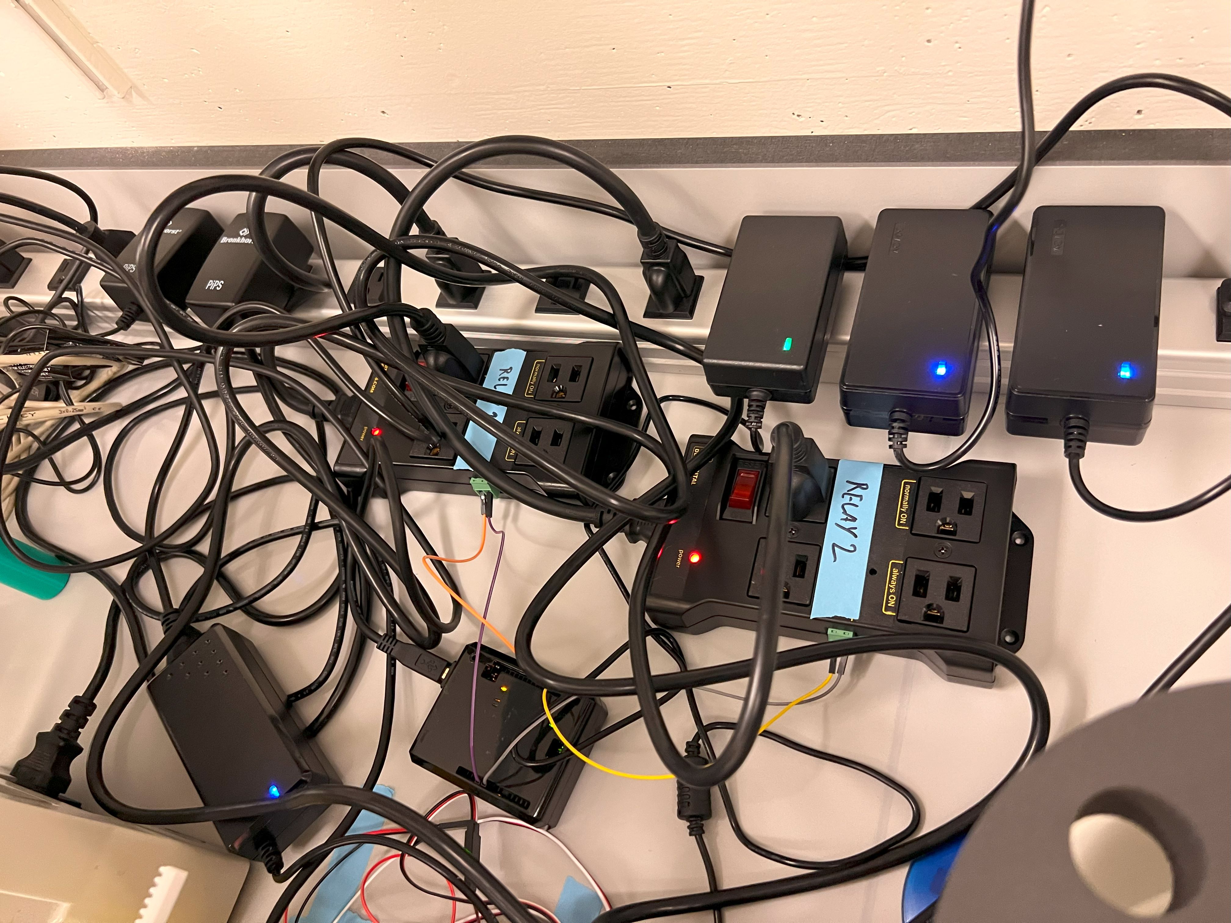
  • Assemble the Vortex Relay Controller

ChronoSeq Device Assembly

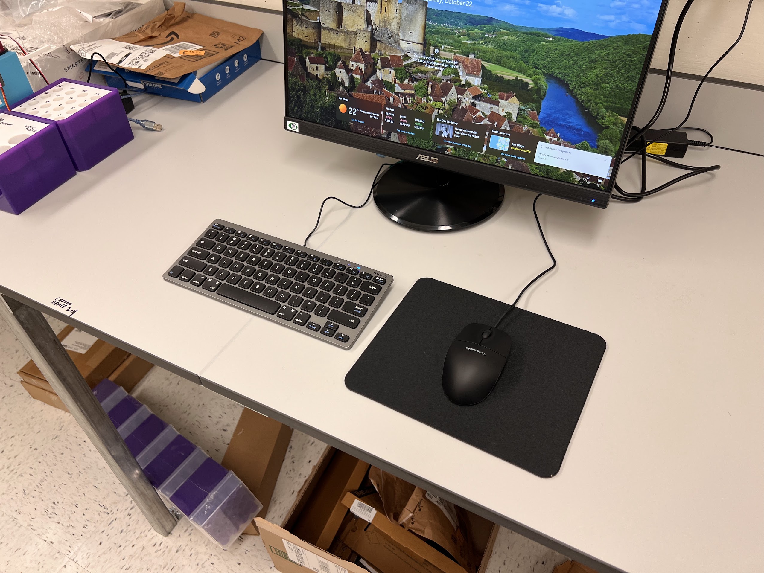
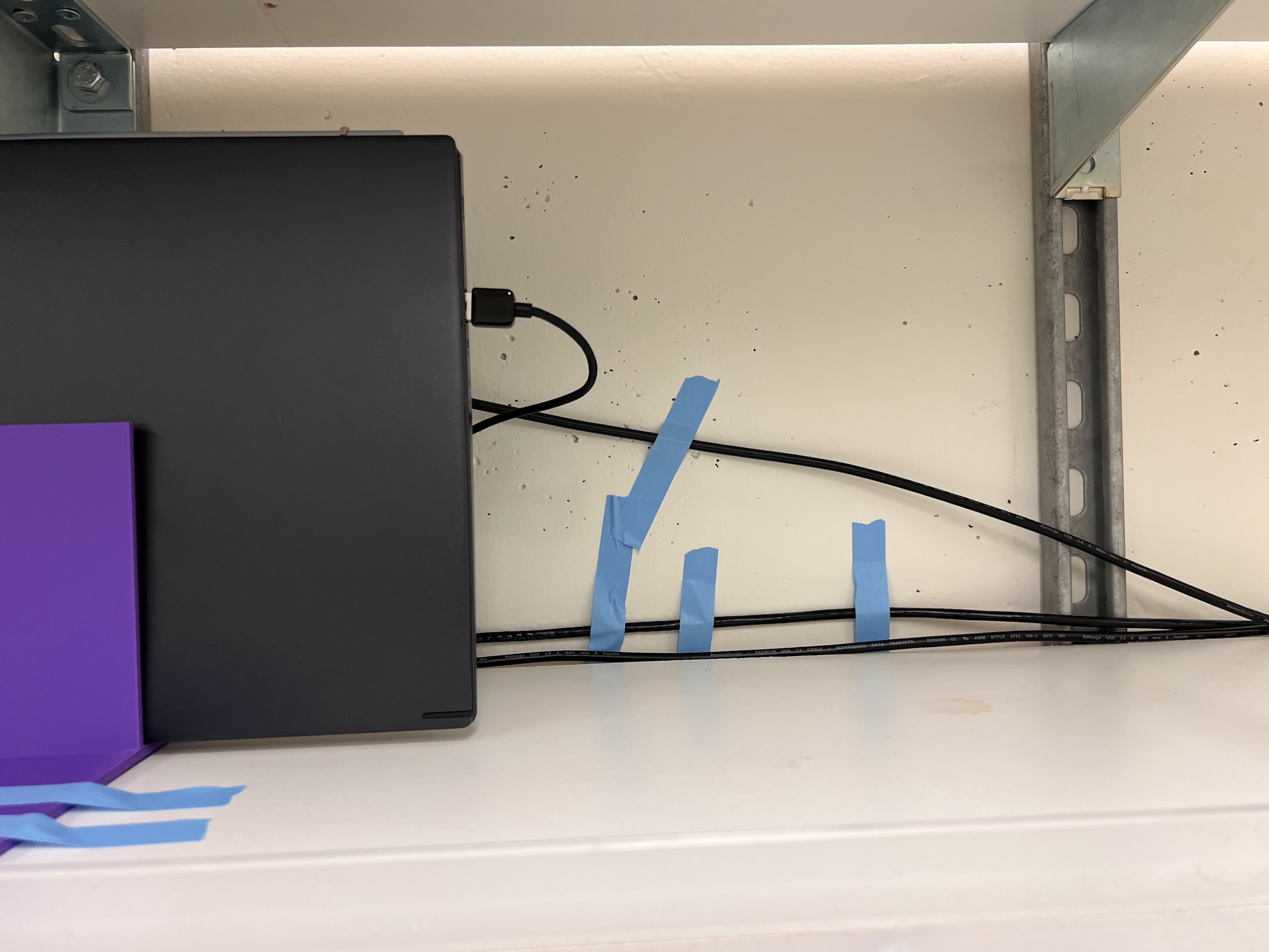
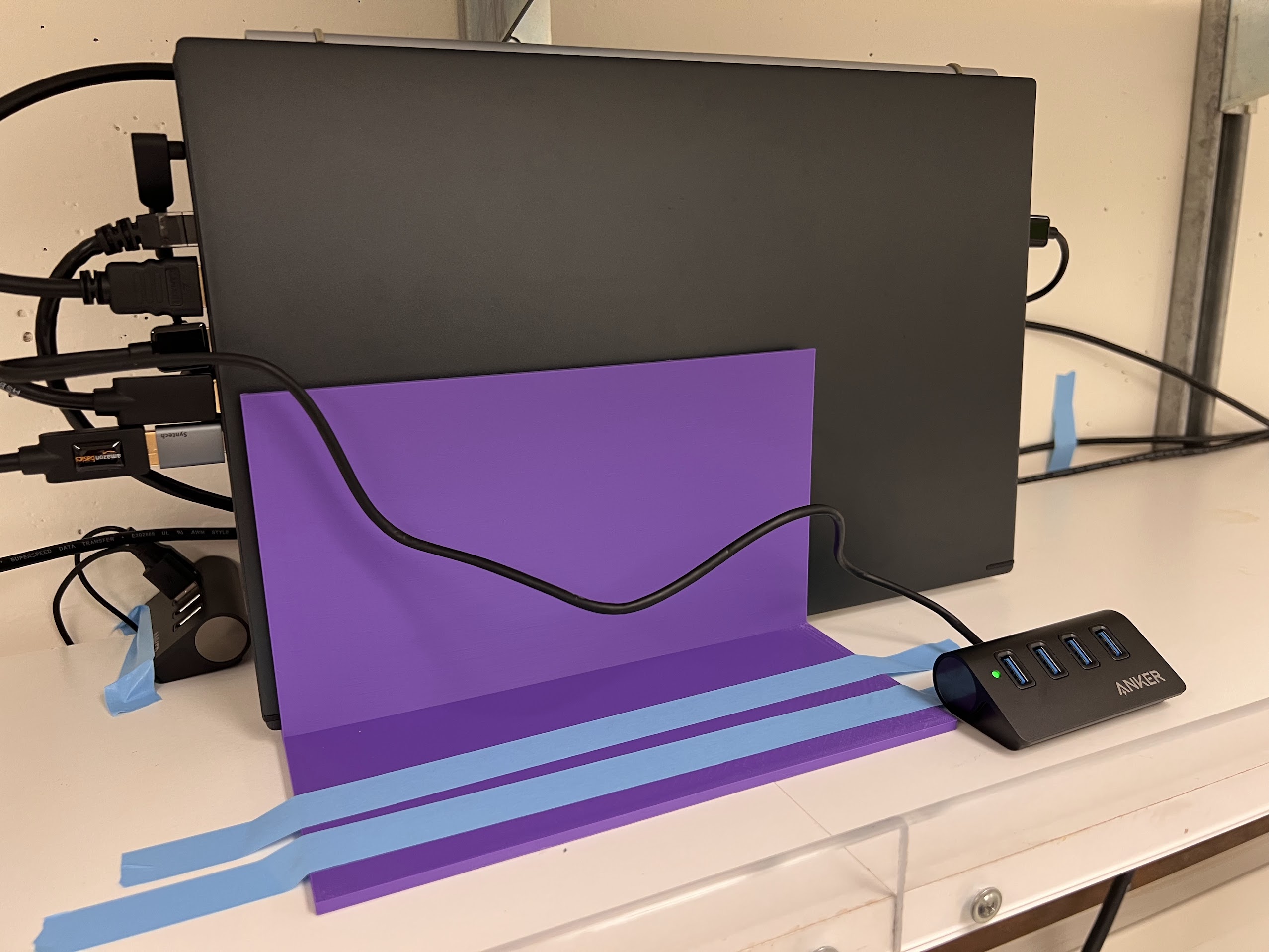
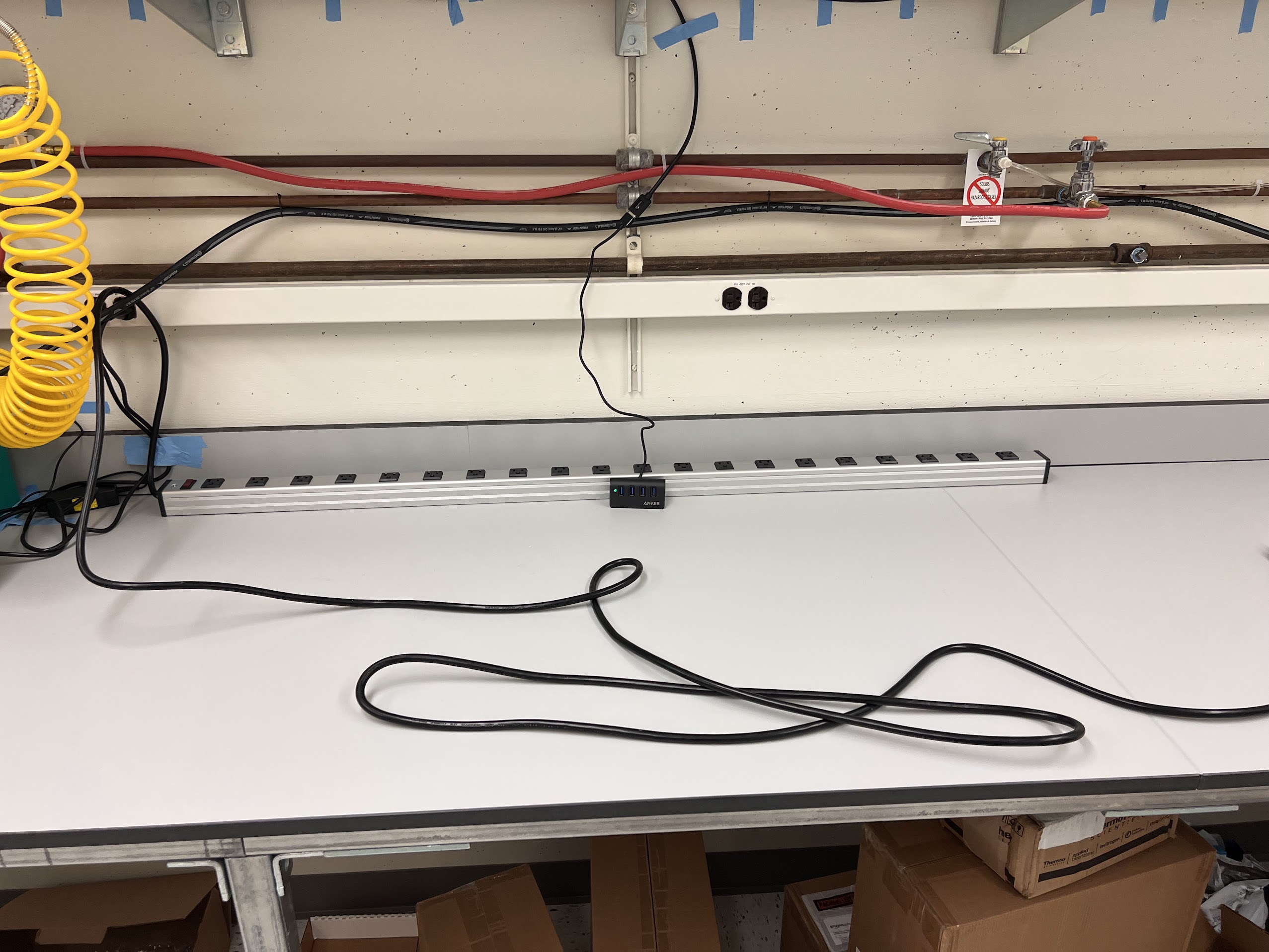
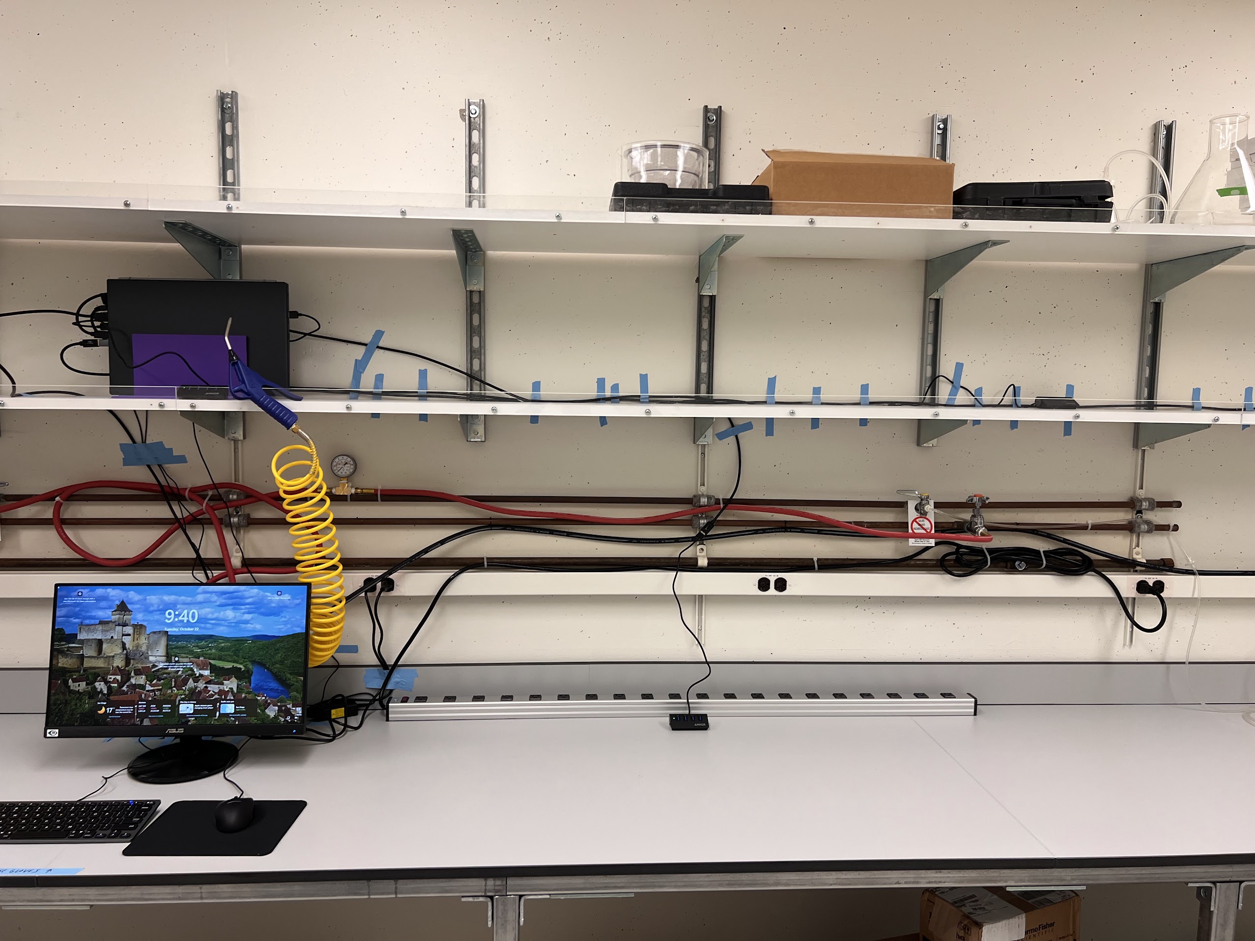
Setting up your Bench

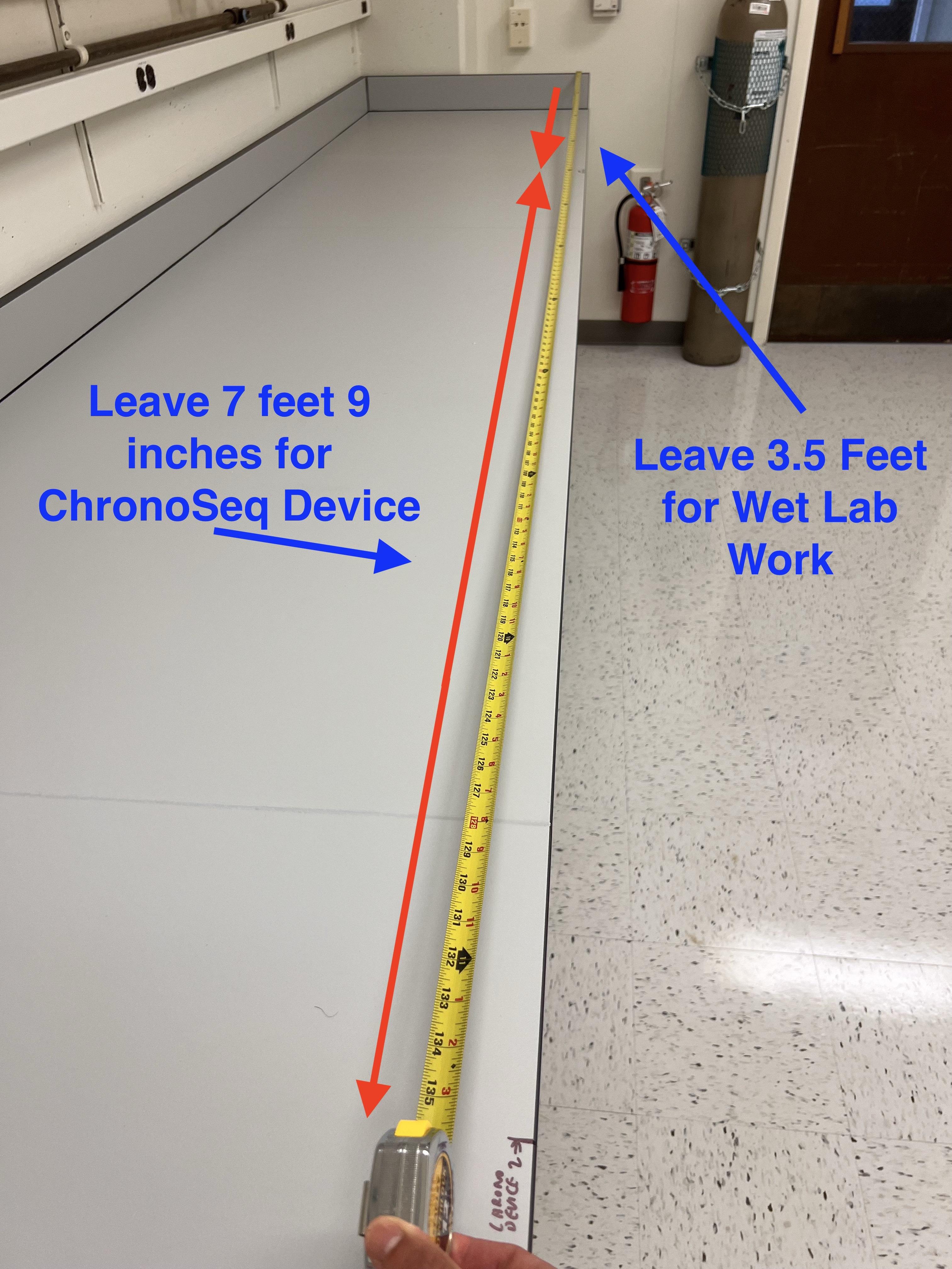
  • The ChronoSeq device needs about 7 feet 9 inches of space on a Standard Wet Lab bench with no obstructions.
    • Leave 3 feet 6 inches of space to the right of the device for the Wet lab parts of the protocol.
    • You can use a 12 foot Tape measure to make the measurements.
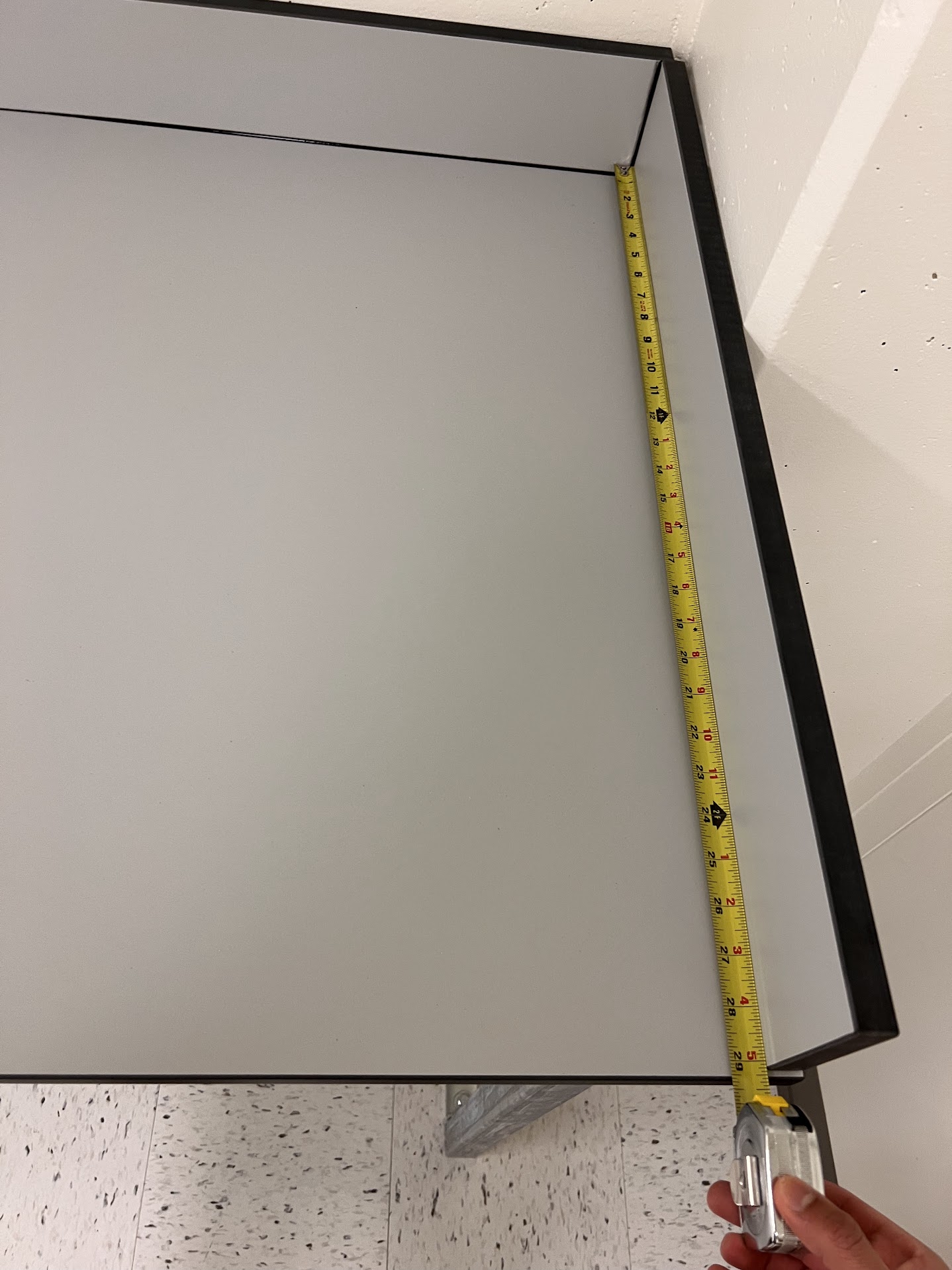
  • Our bench was 2 feet 5.25 inches deep.
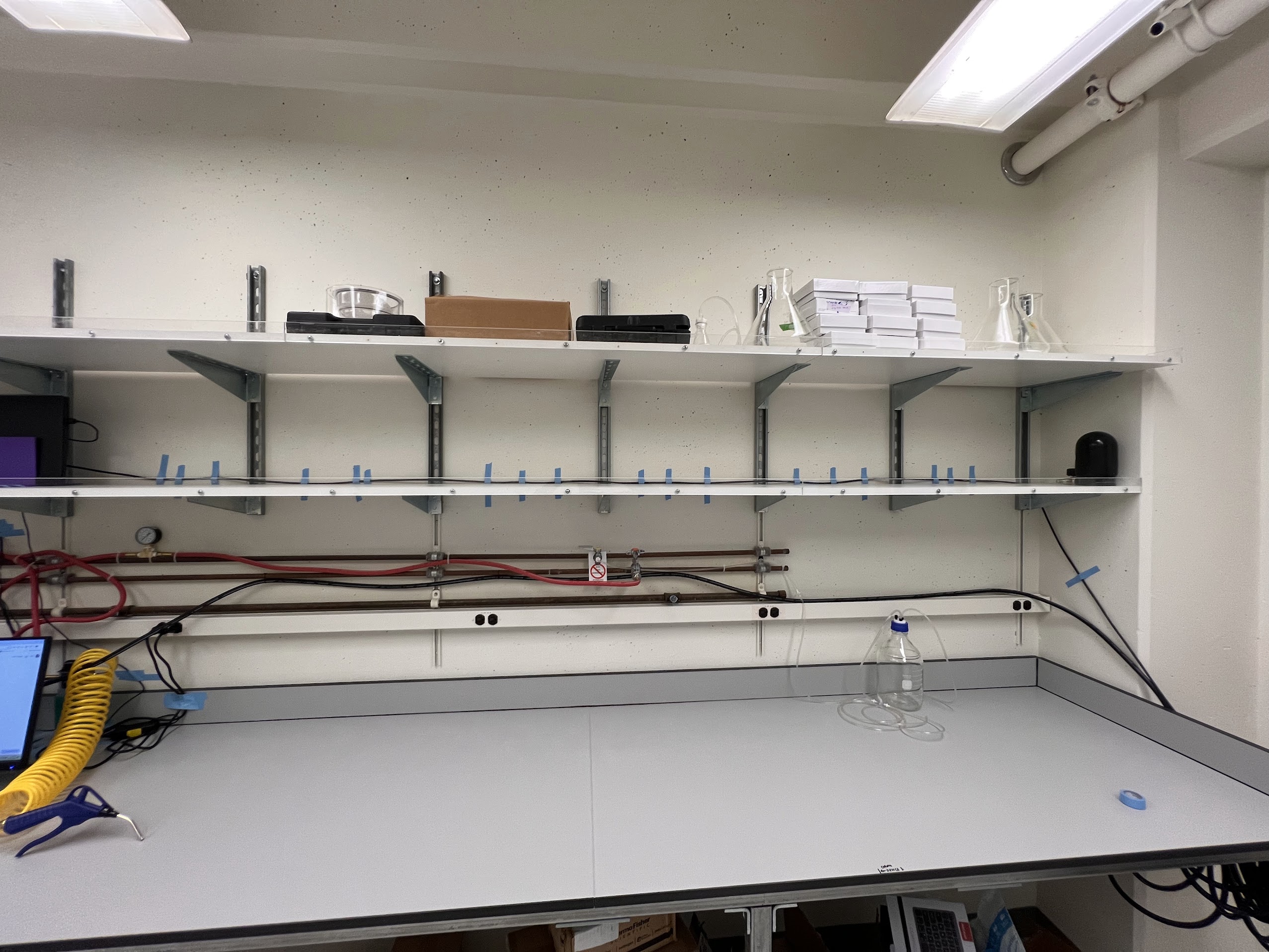
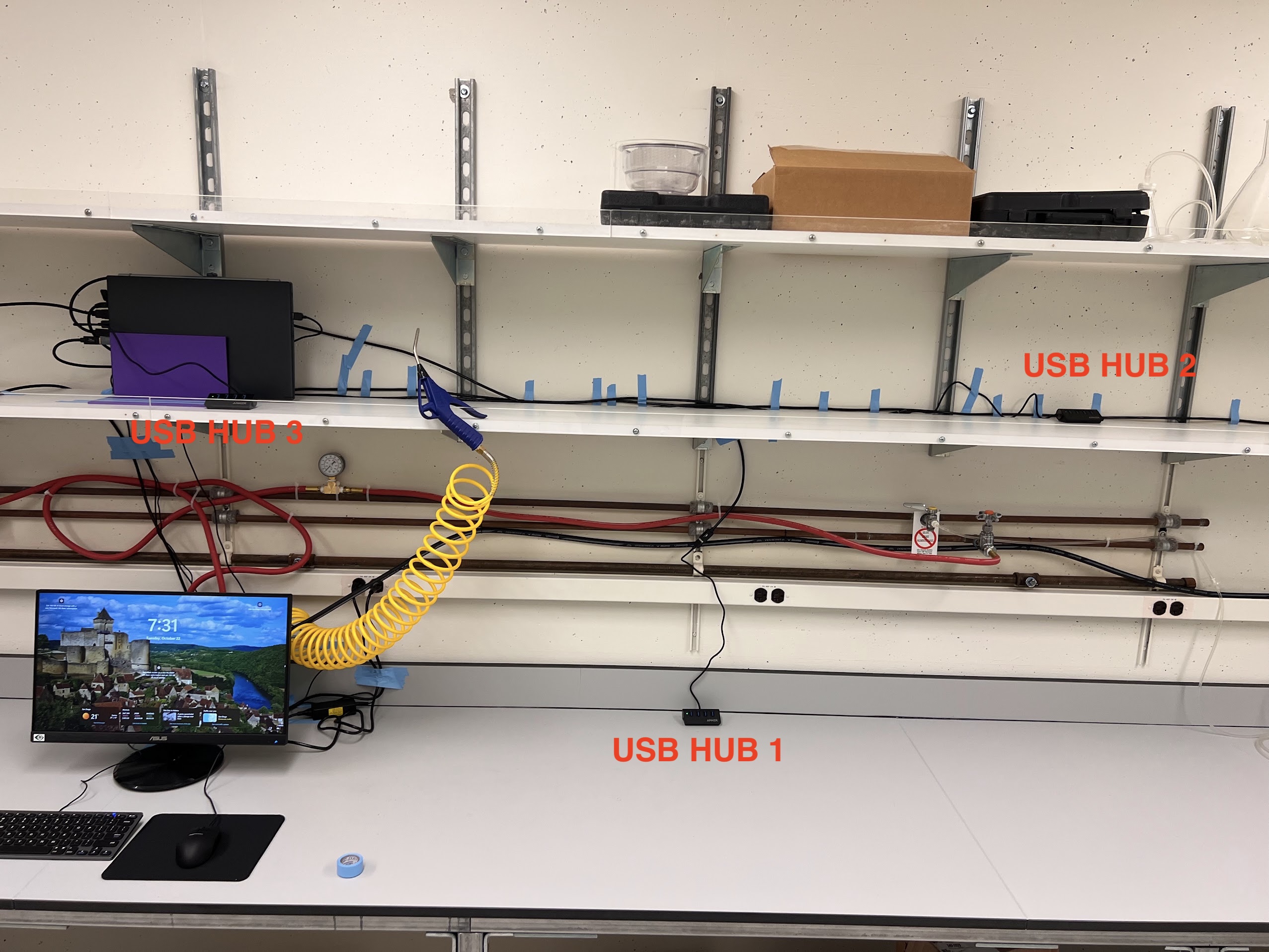
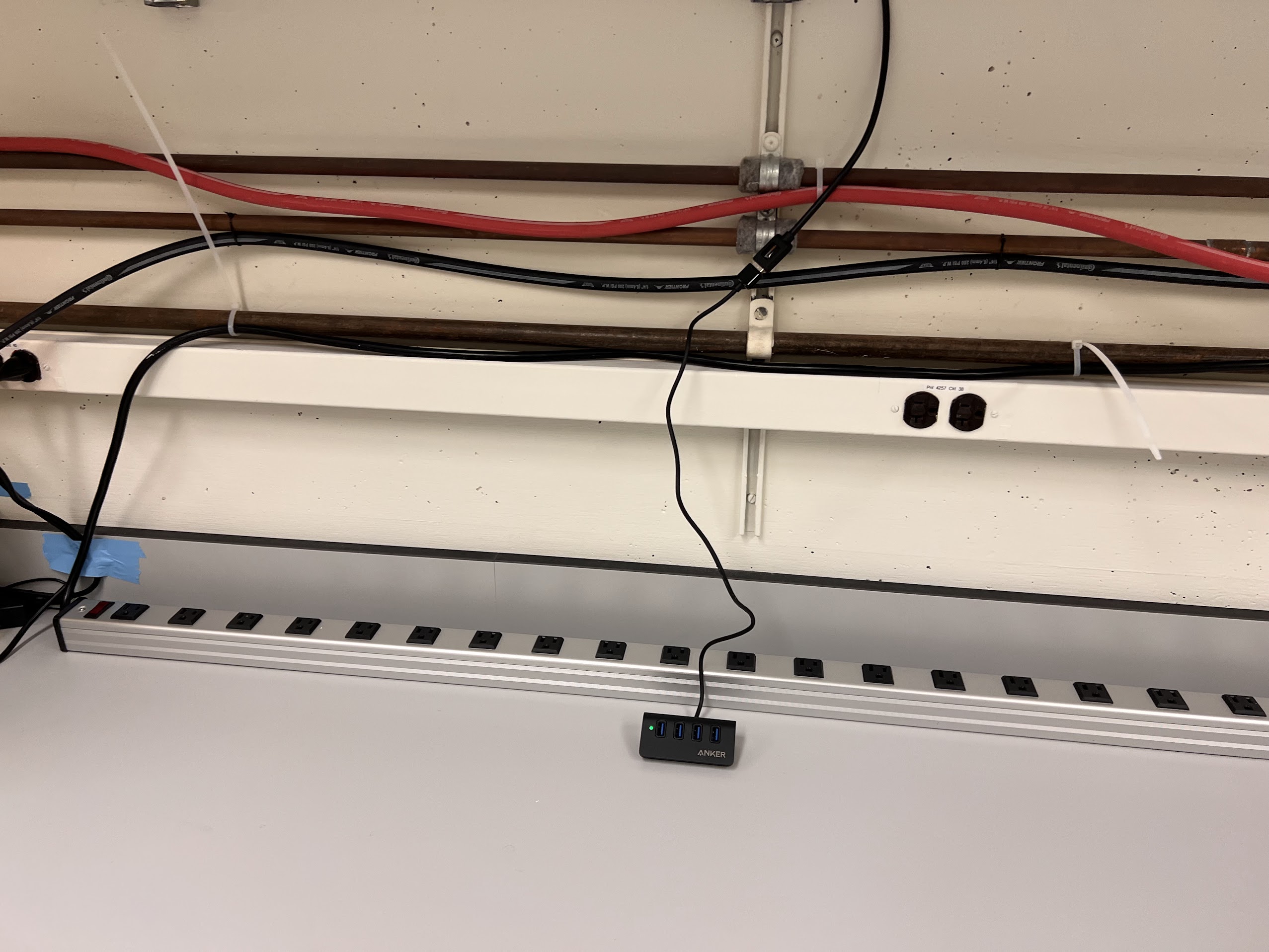
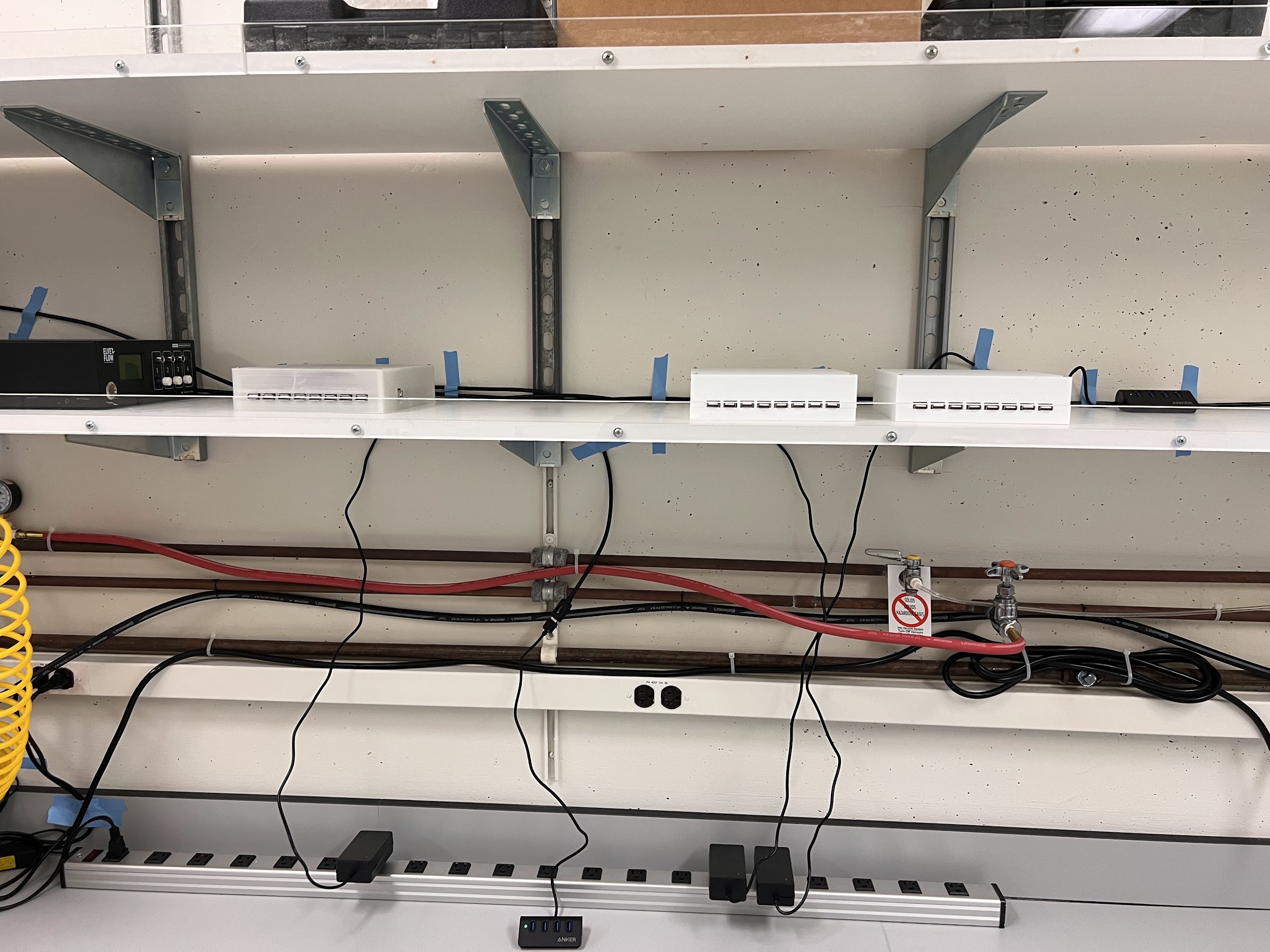
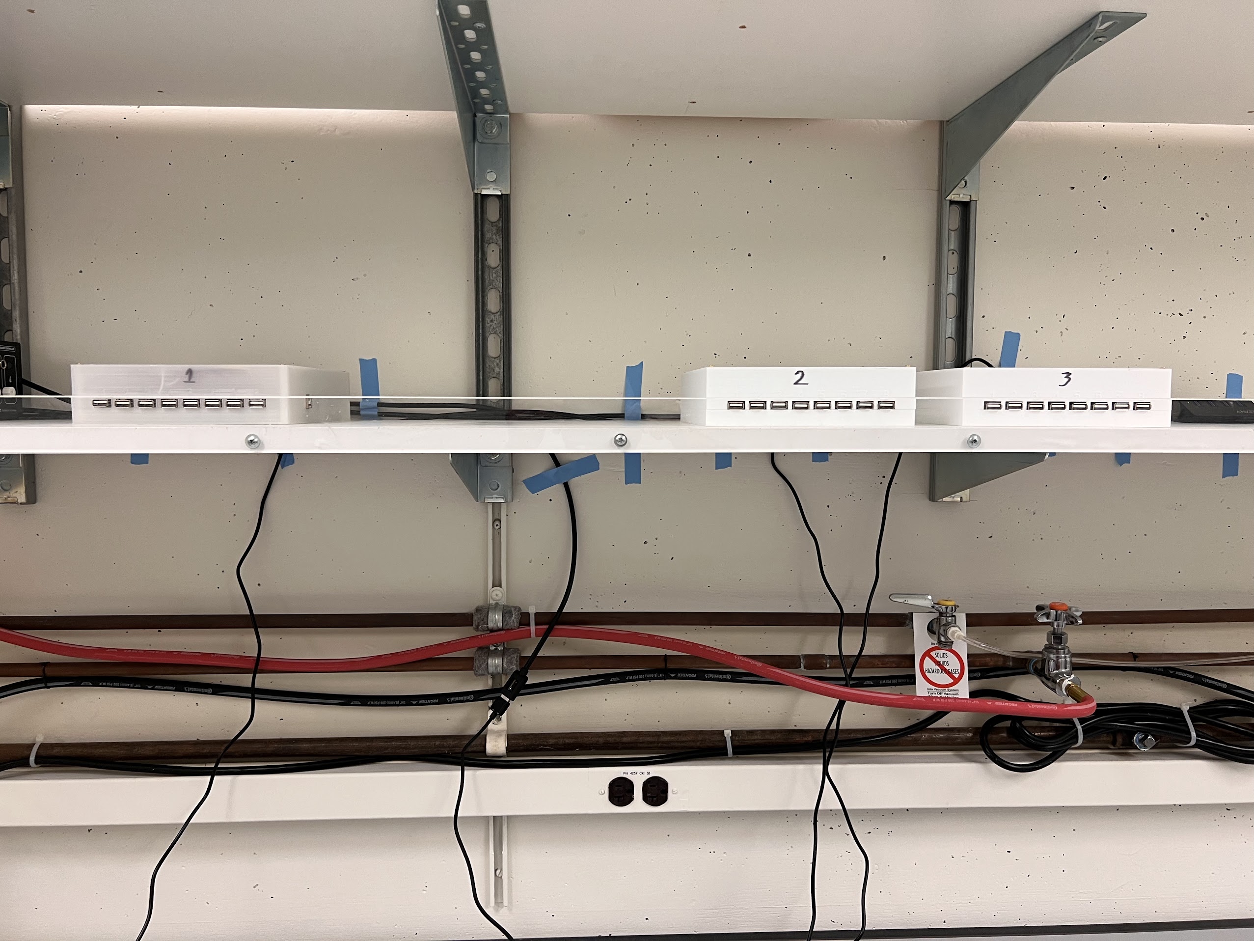
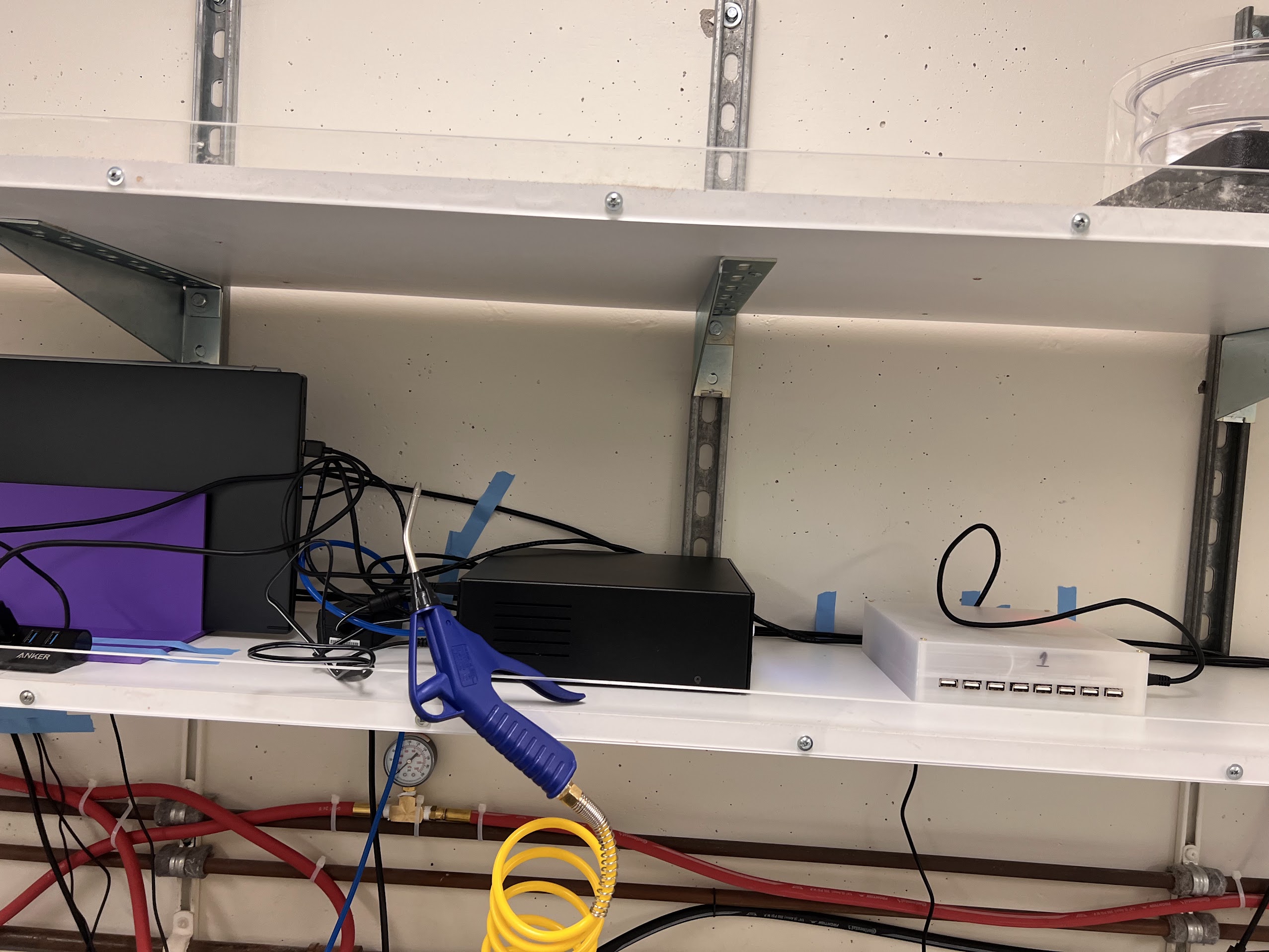
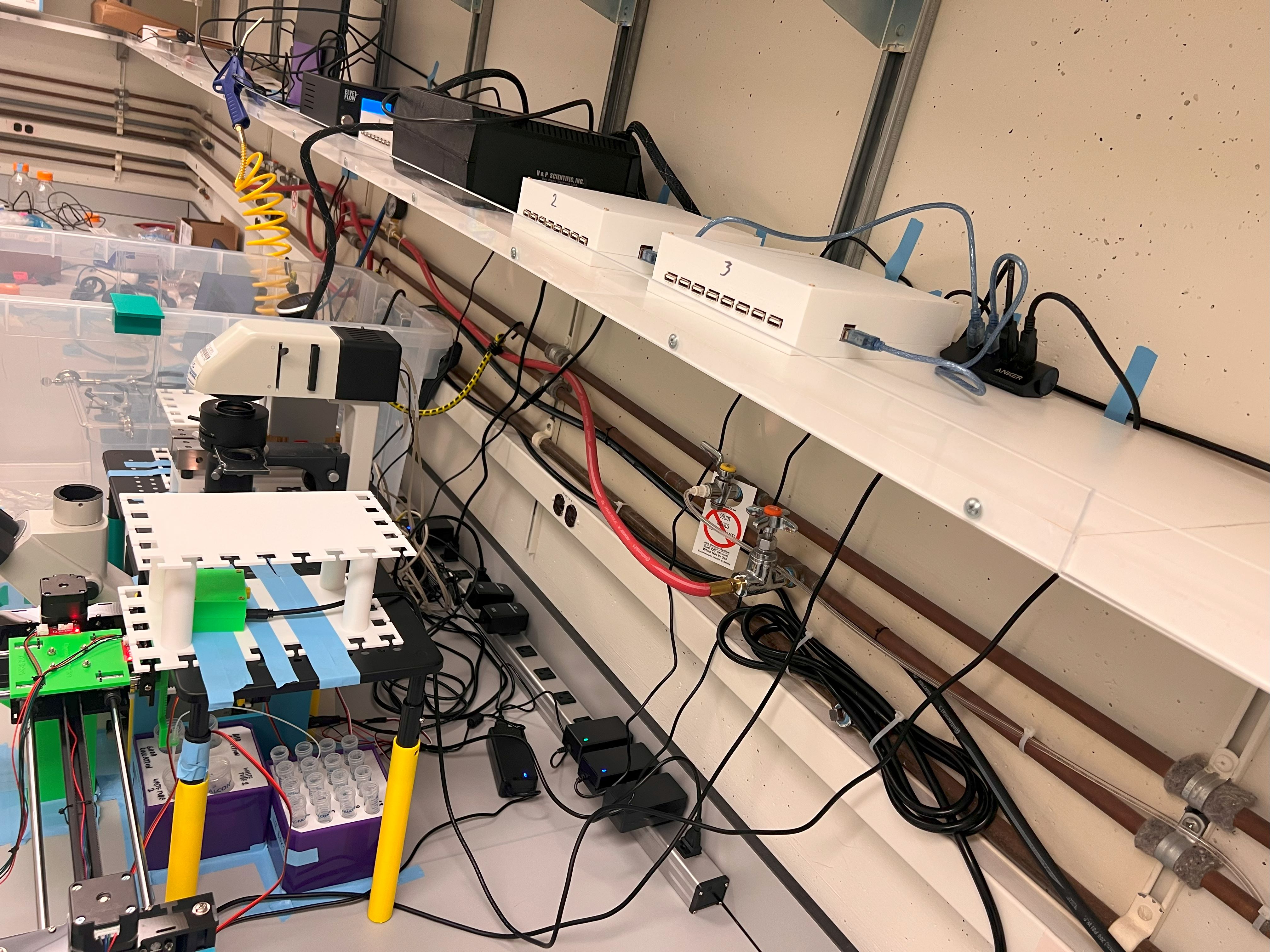
  • The rack space directly above this space should also be kept empty for housing many components.
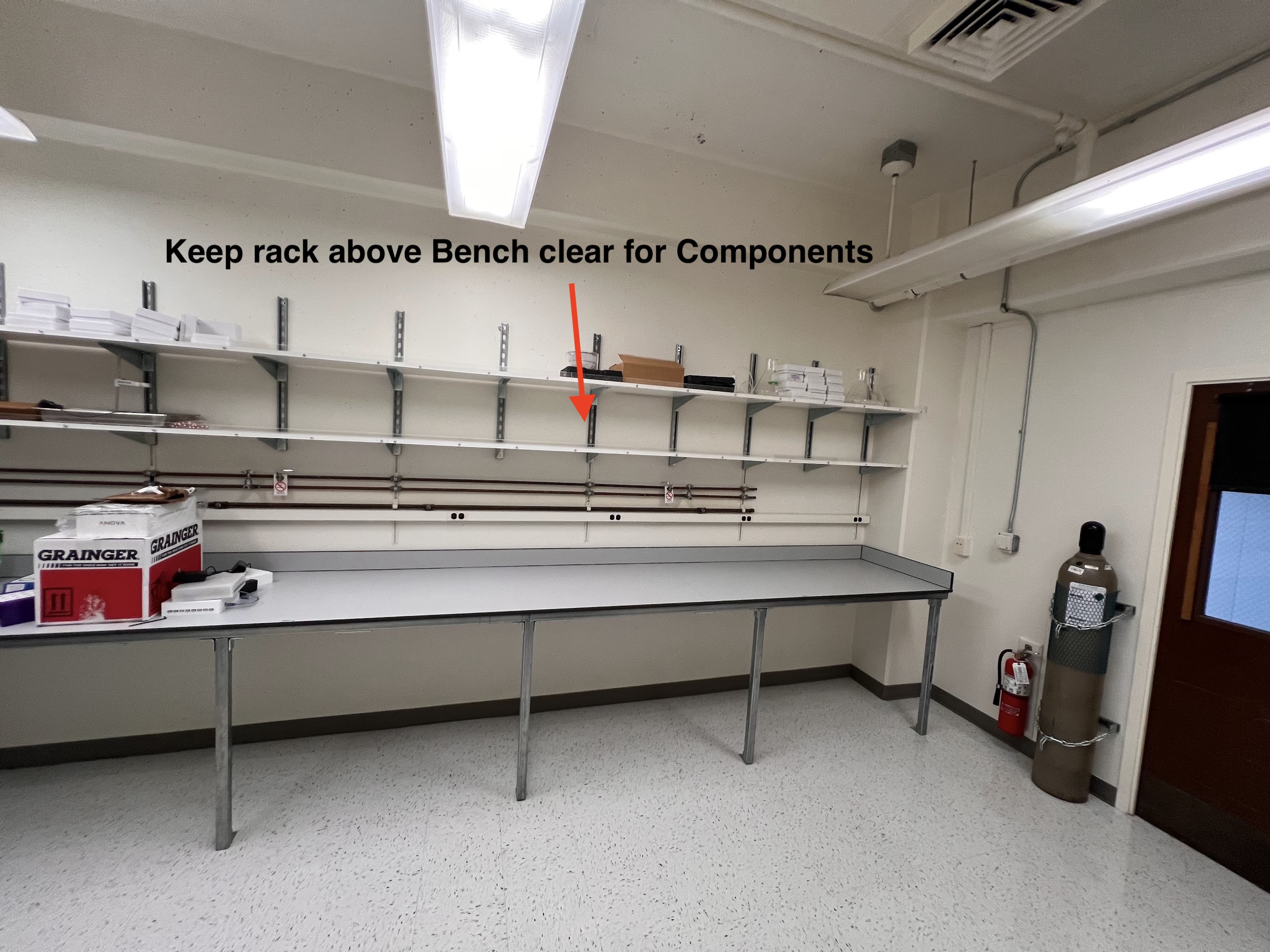
  • The dimensions for the rack space is as follows:
    • The distance between the support pieces is 21 inches.
    • The distance between the racks is 13 inches.
    • The depth of the racks is 13 inches.
Distance between support pieces Height/Distance between racks Depth of rack
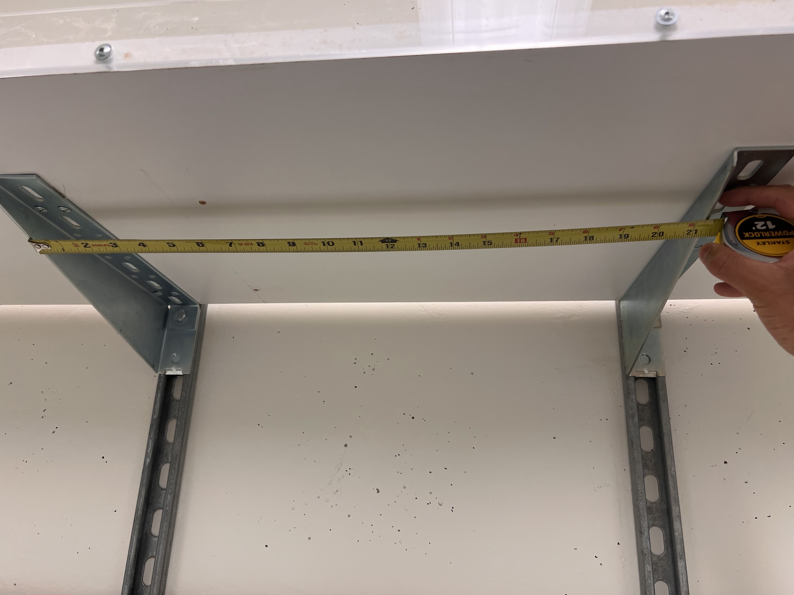
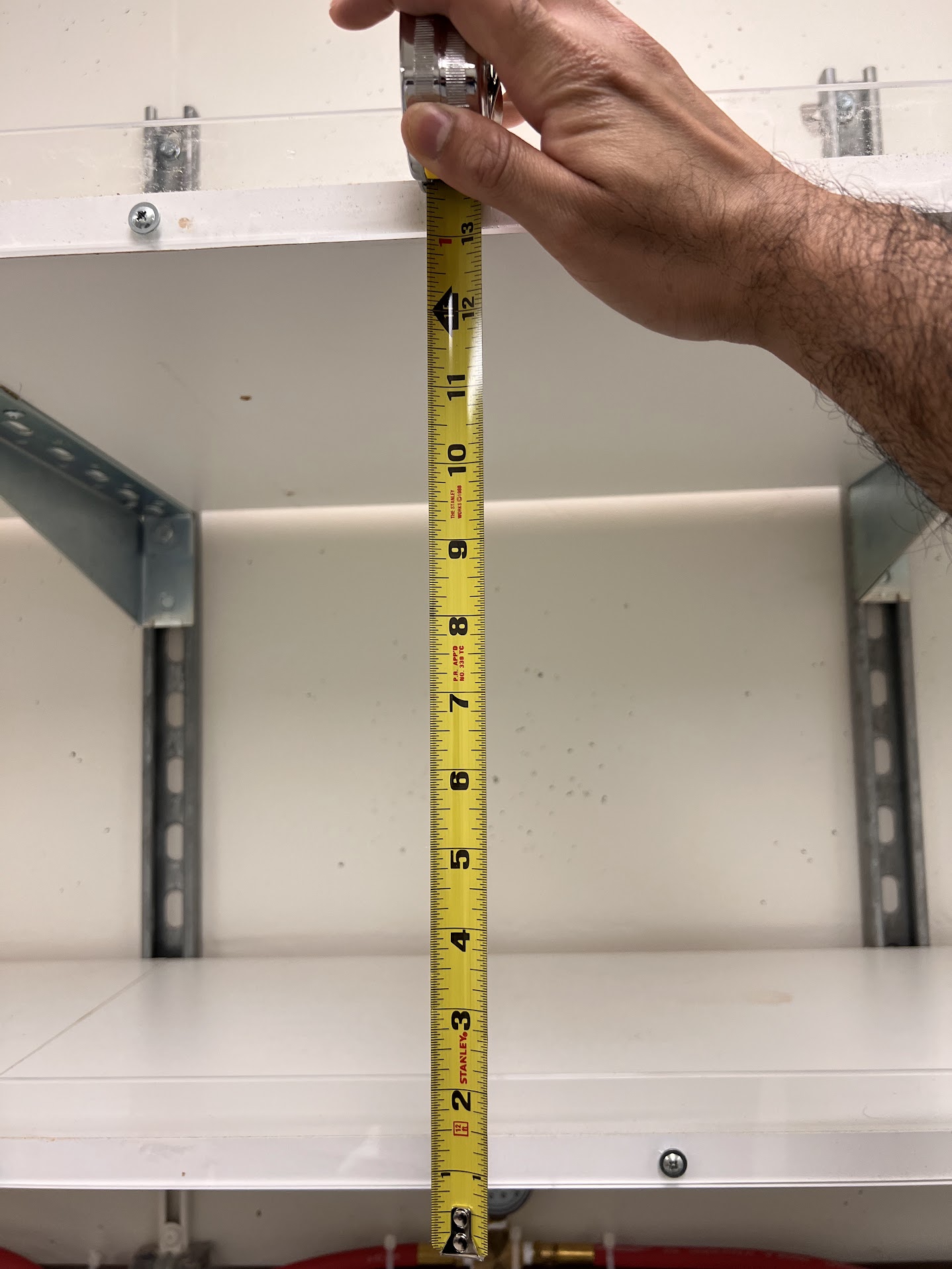
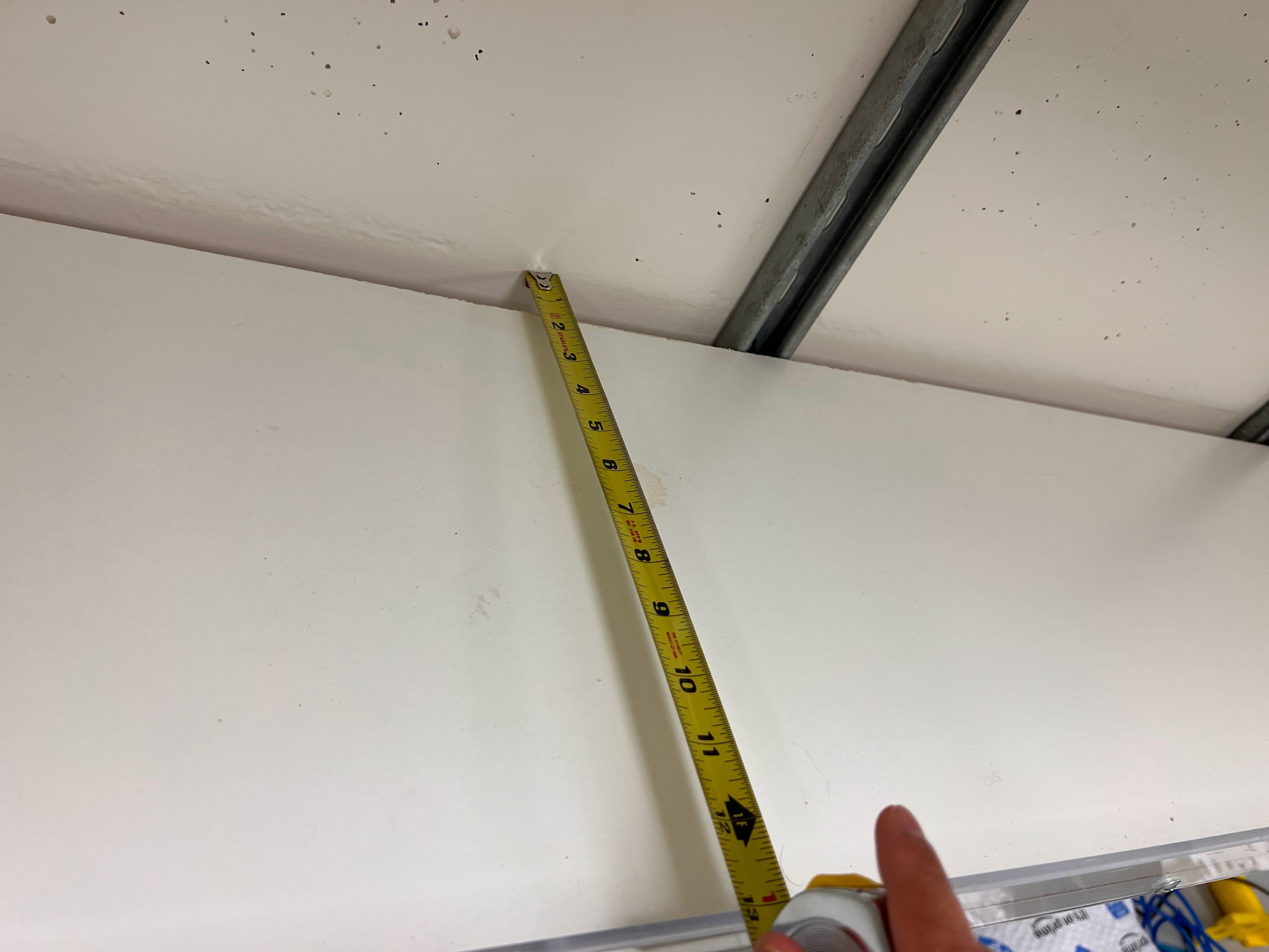
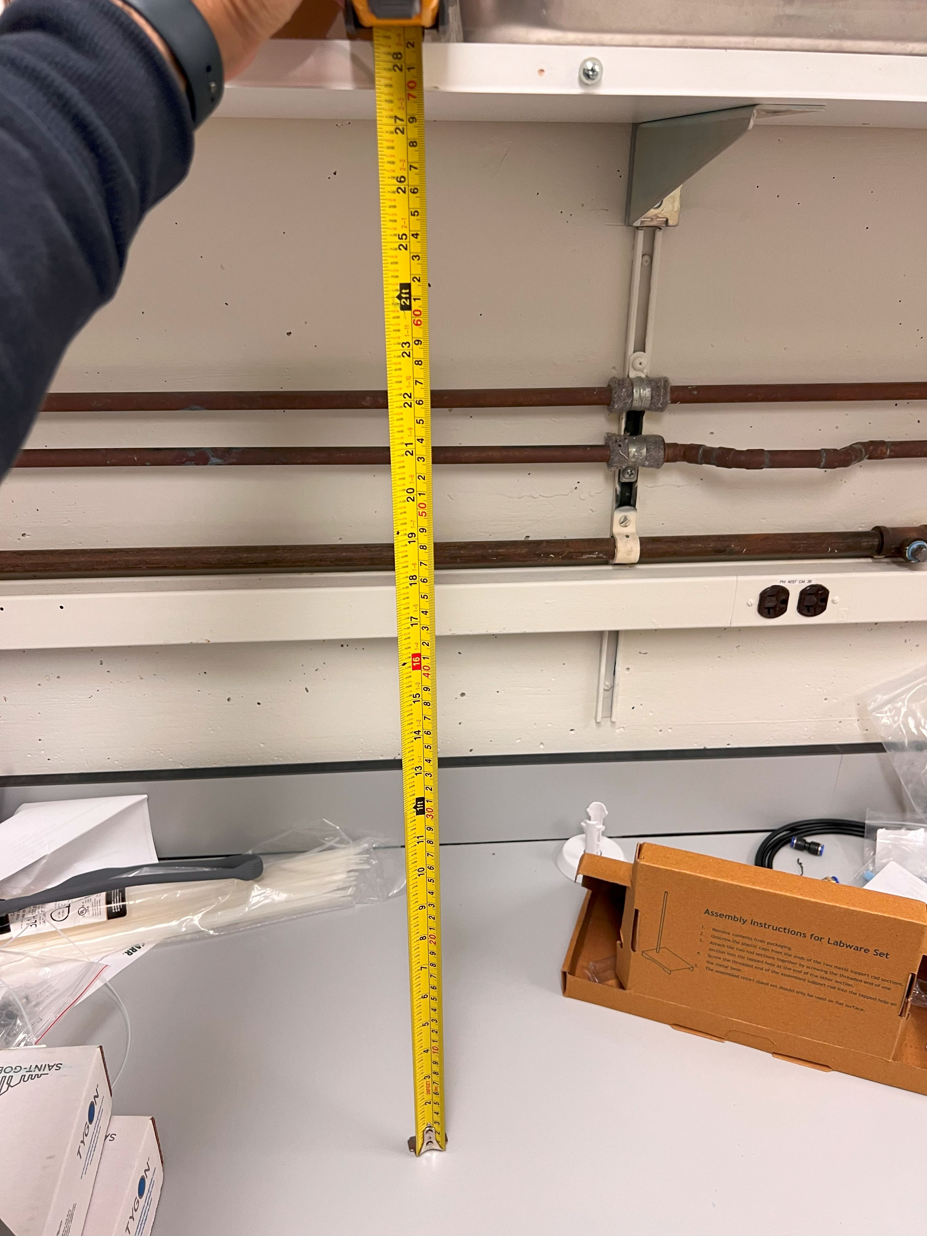
  • The first rack is 28 inches above the bench.

  • We also kept a 5%CO2 cylinder close to the bench.

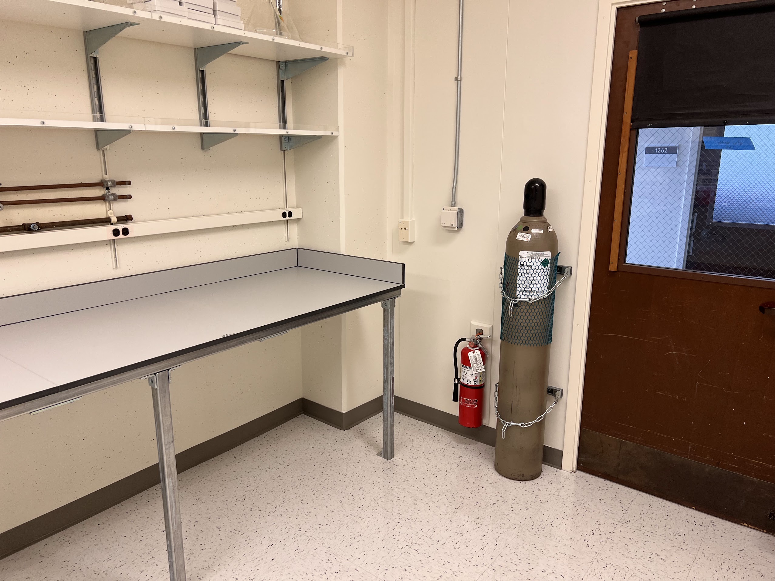
    • Cylinder was secured in place with restraints.
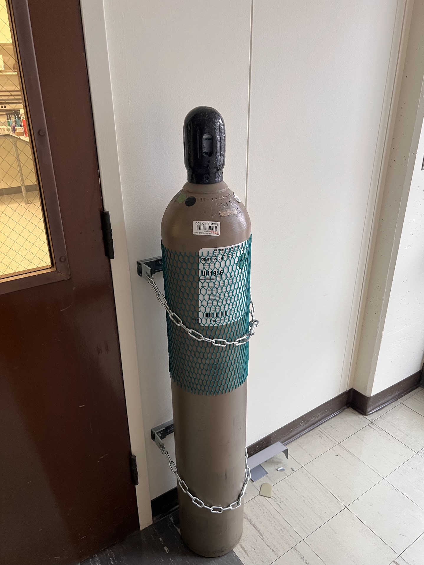
  • An additional backup cylinder was also kept in the hallway secured with restraints.

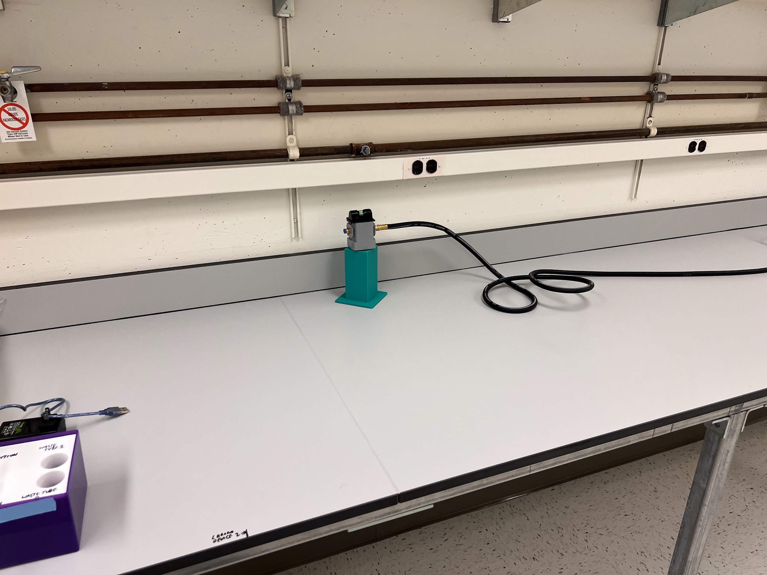
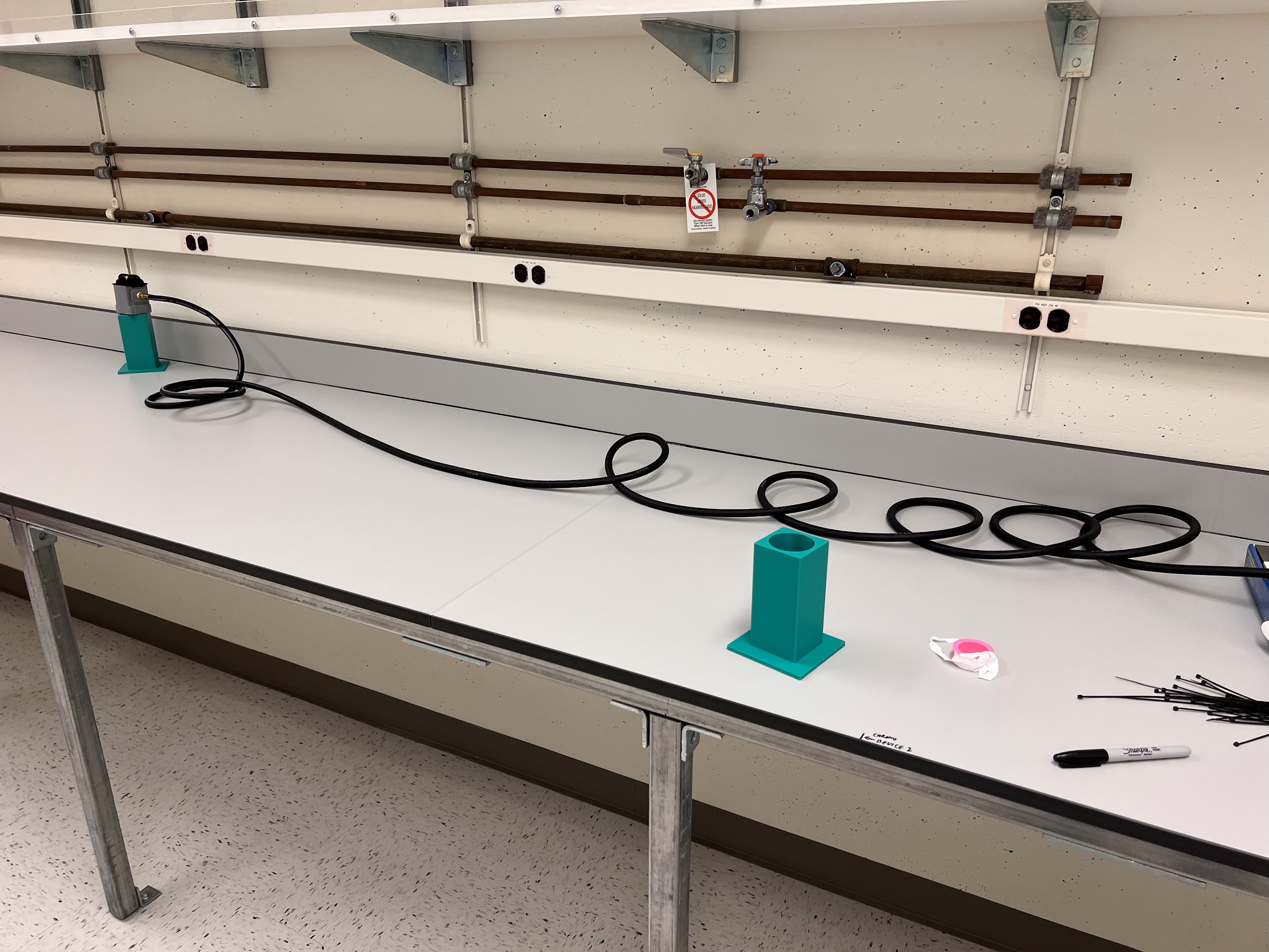
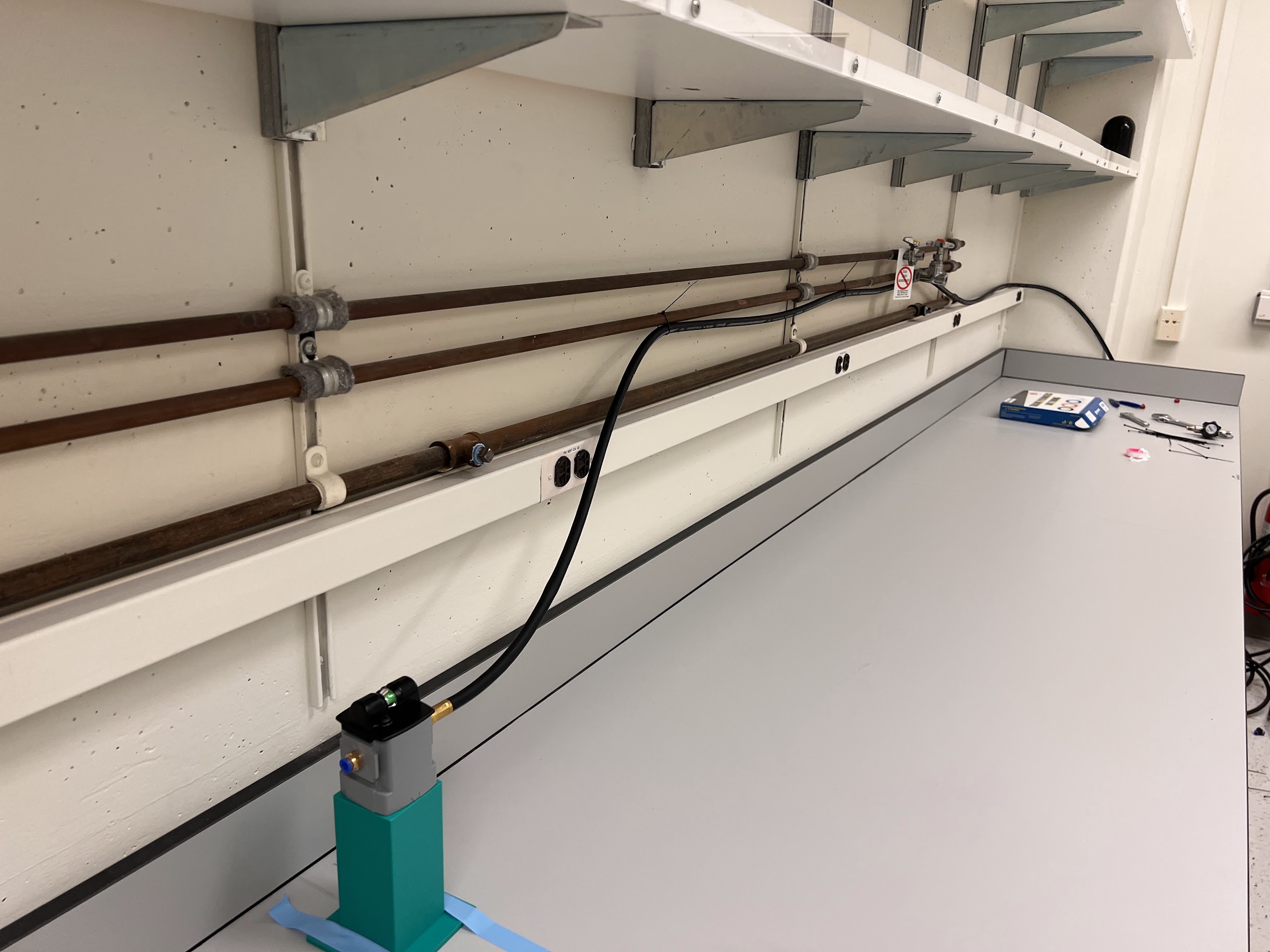
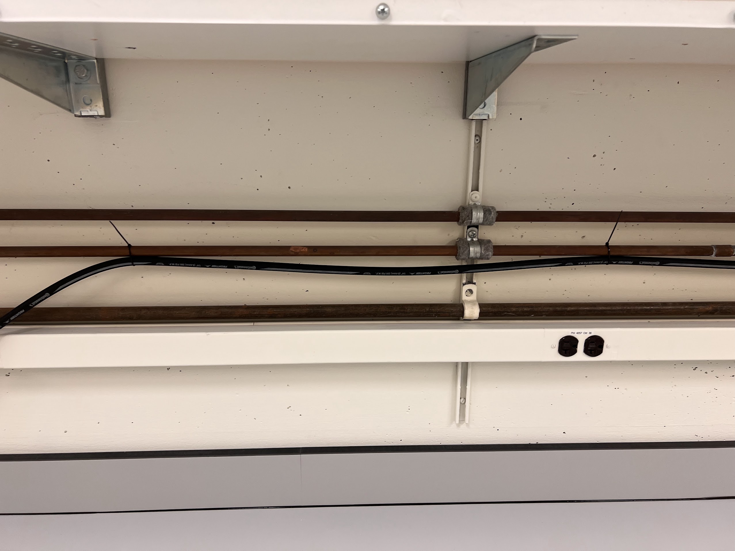
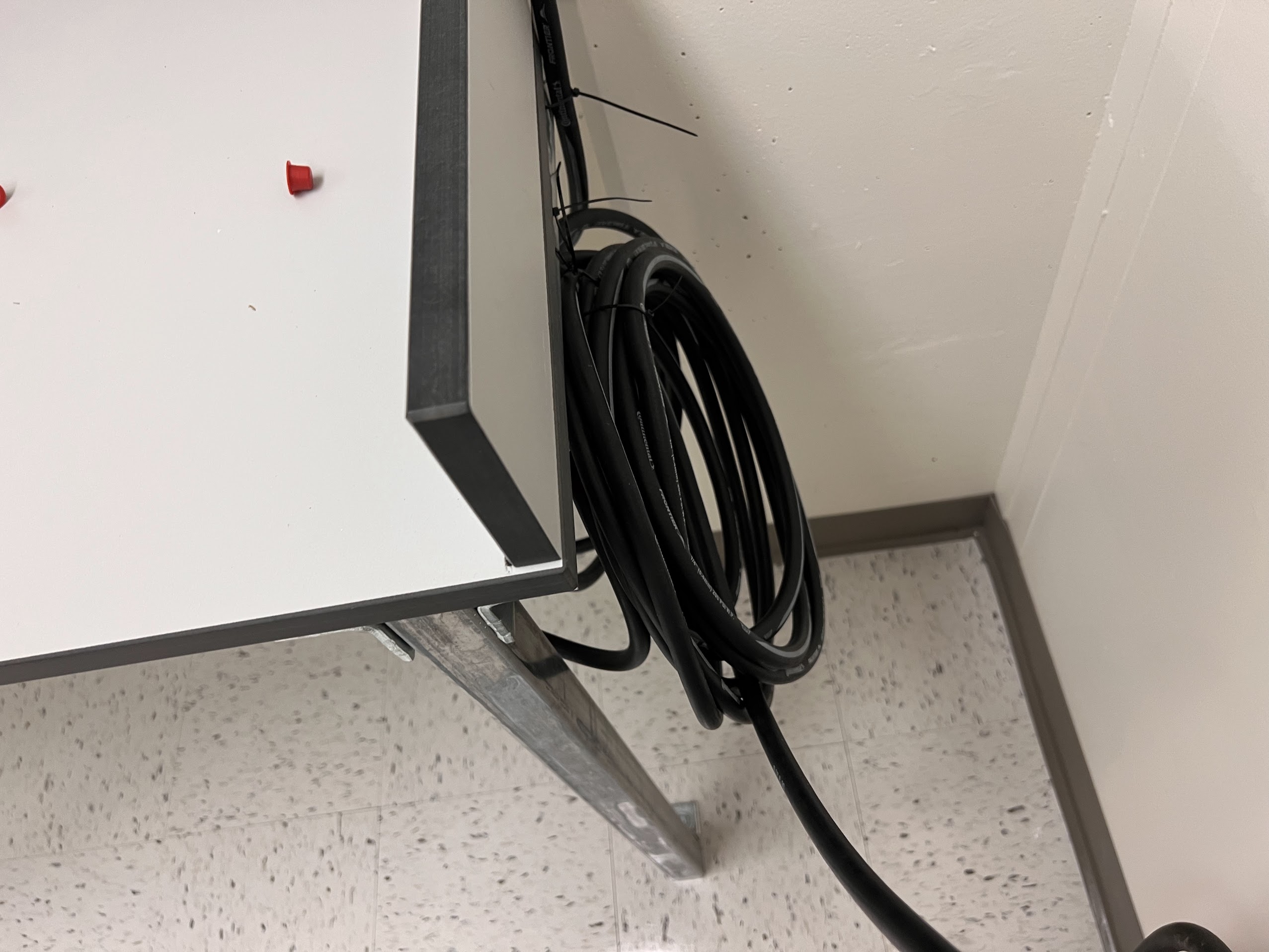
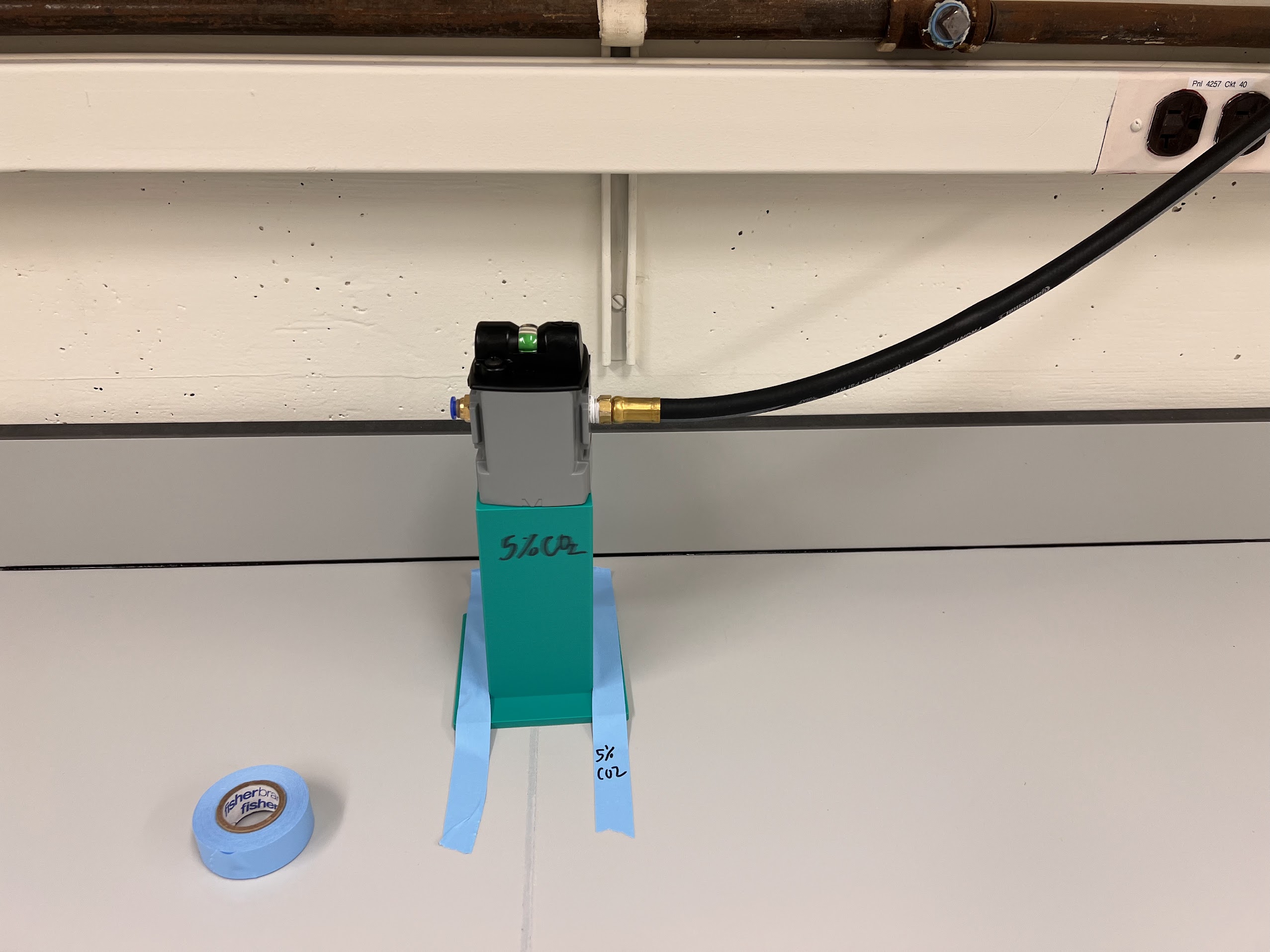
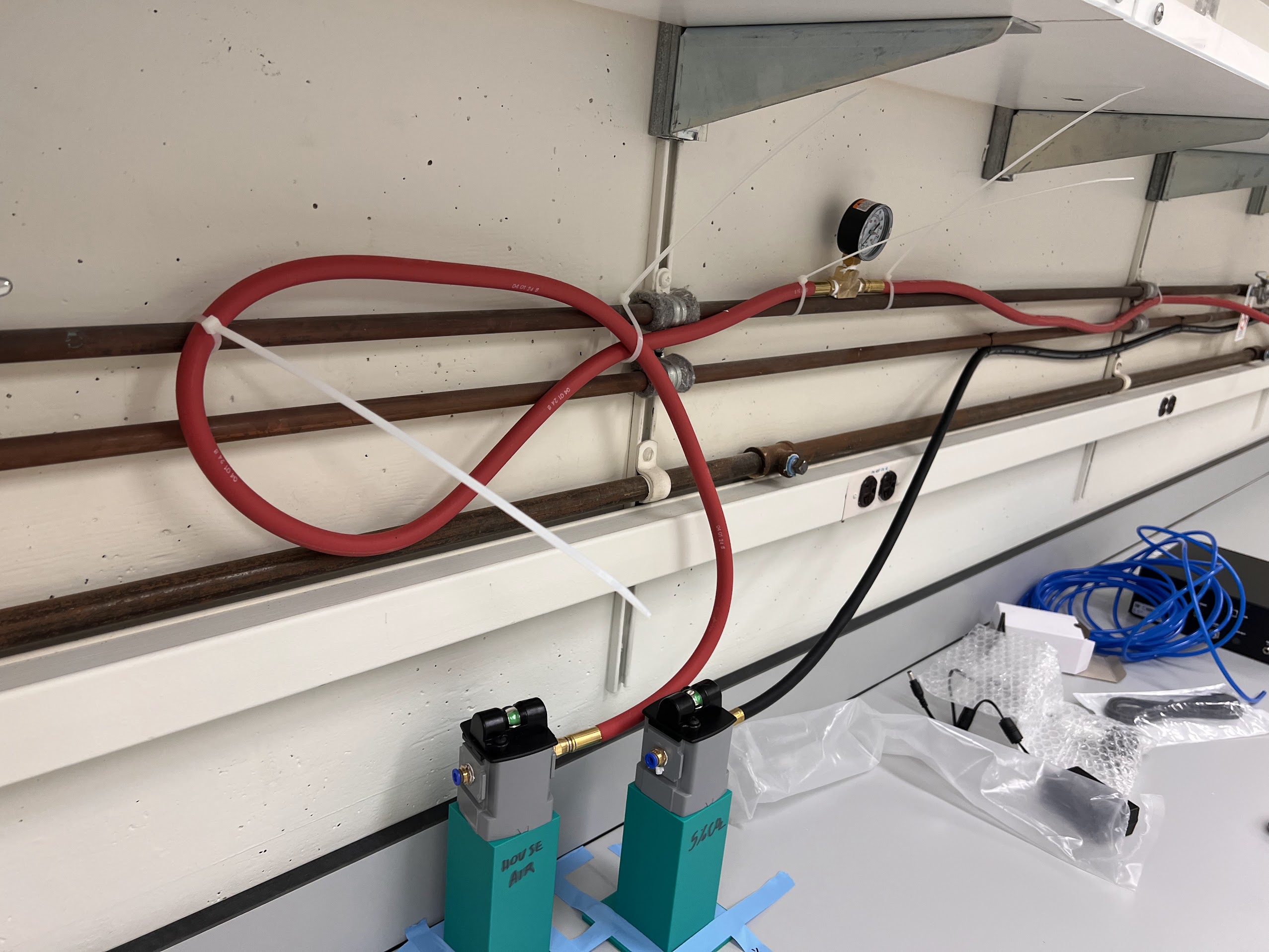
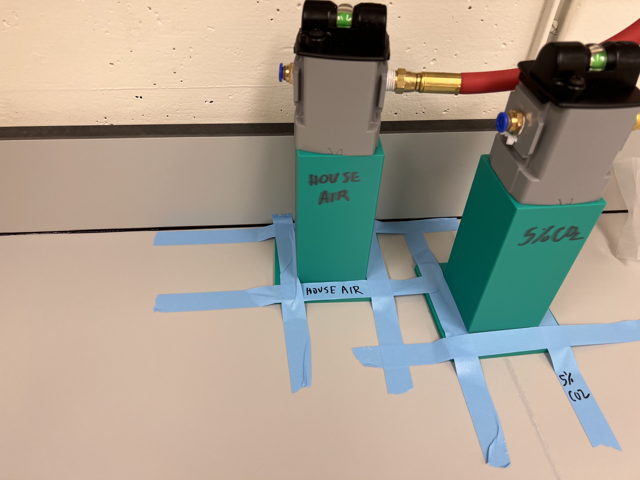
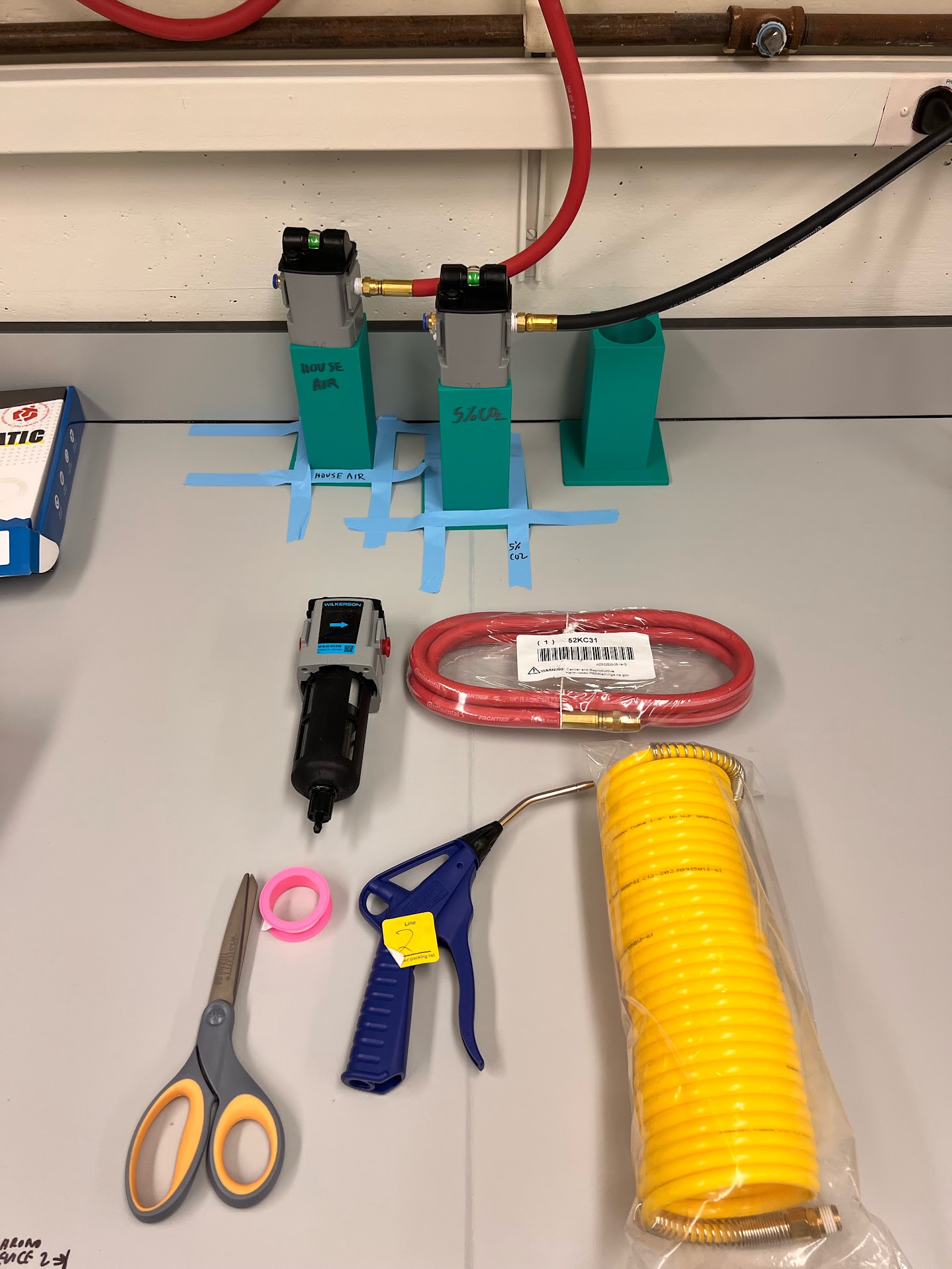
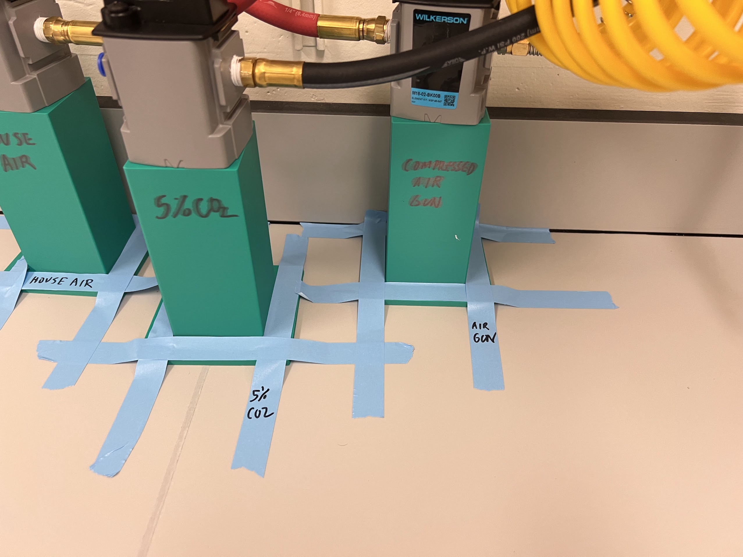
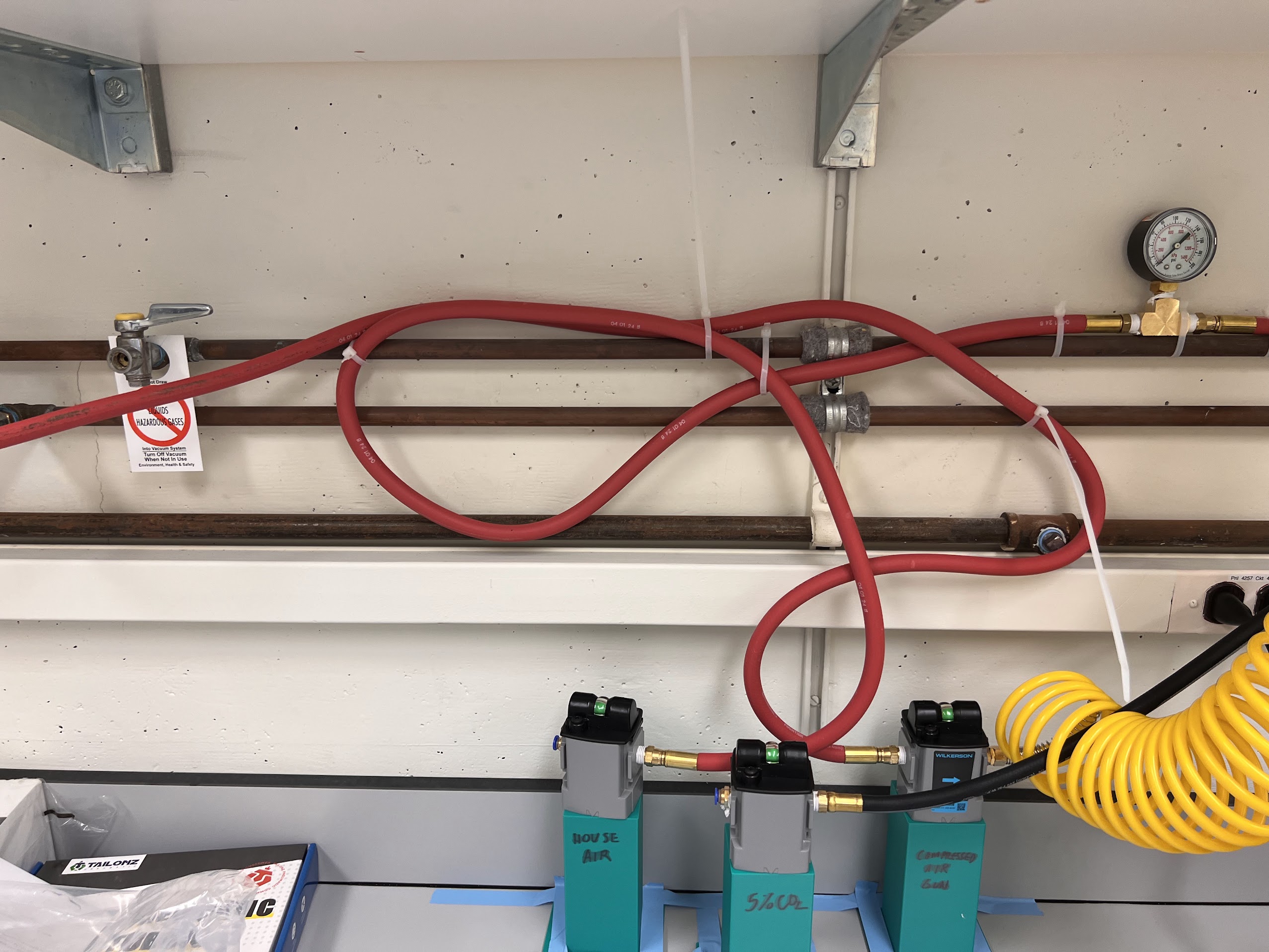
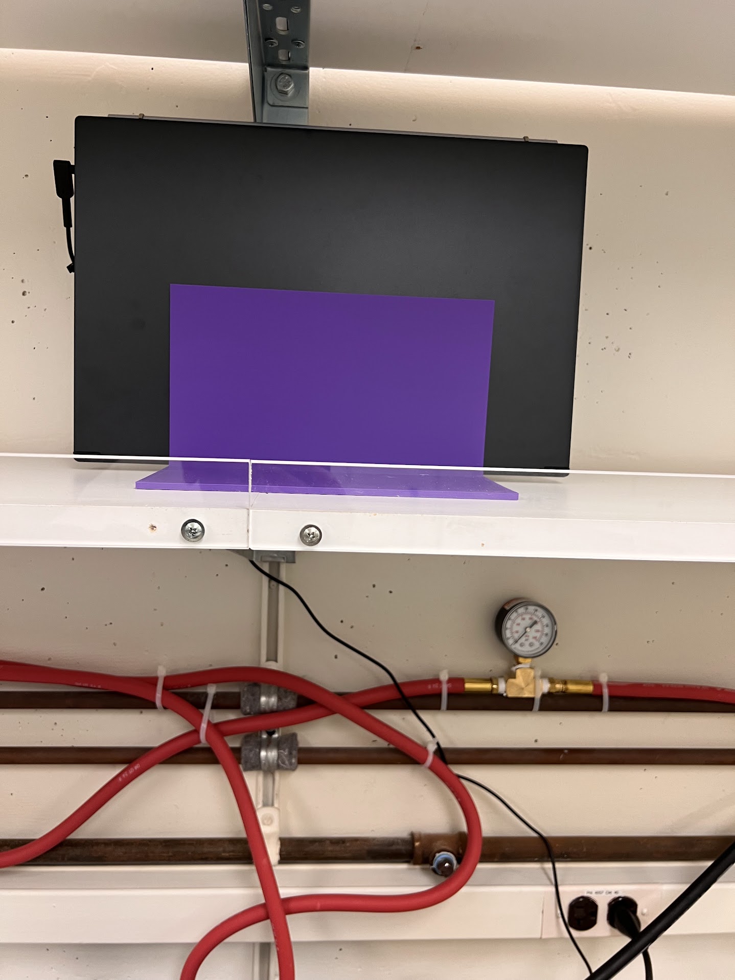
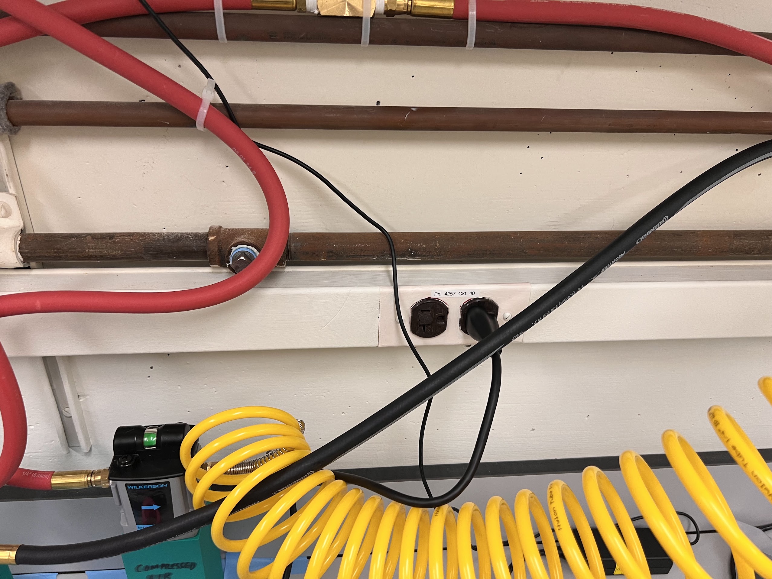
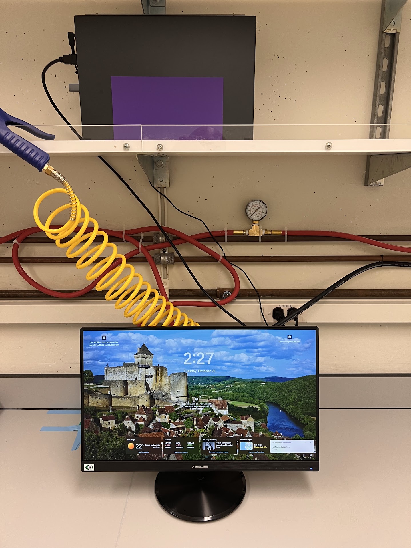
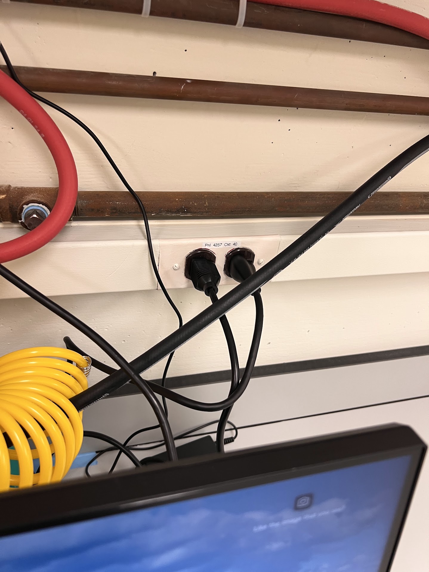
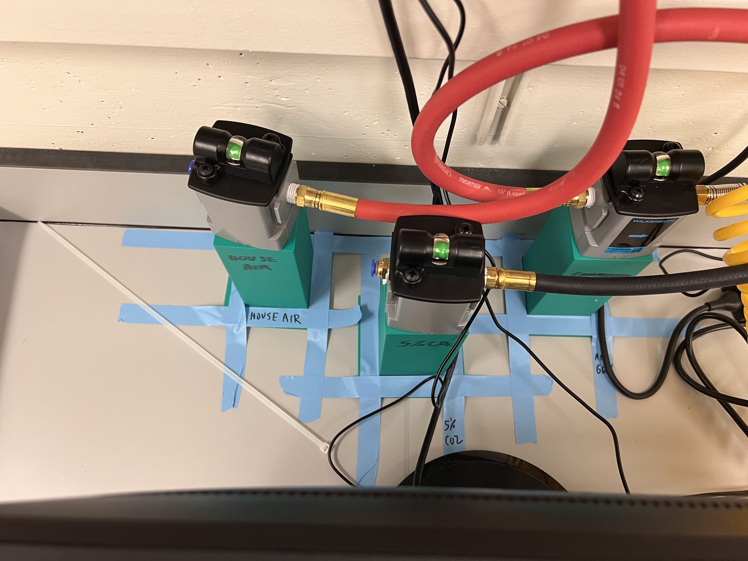
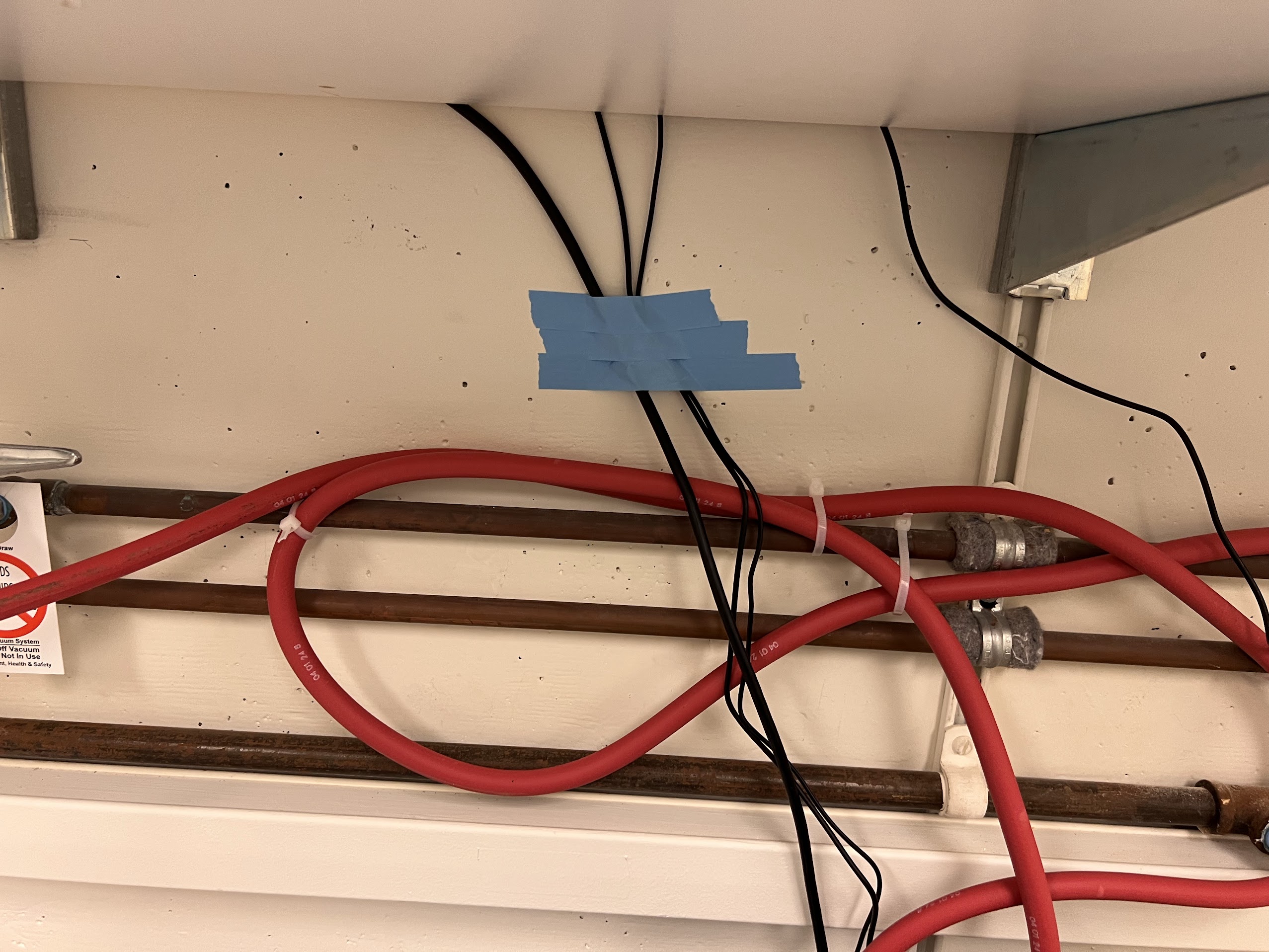
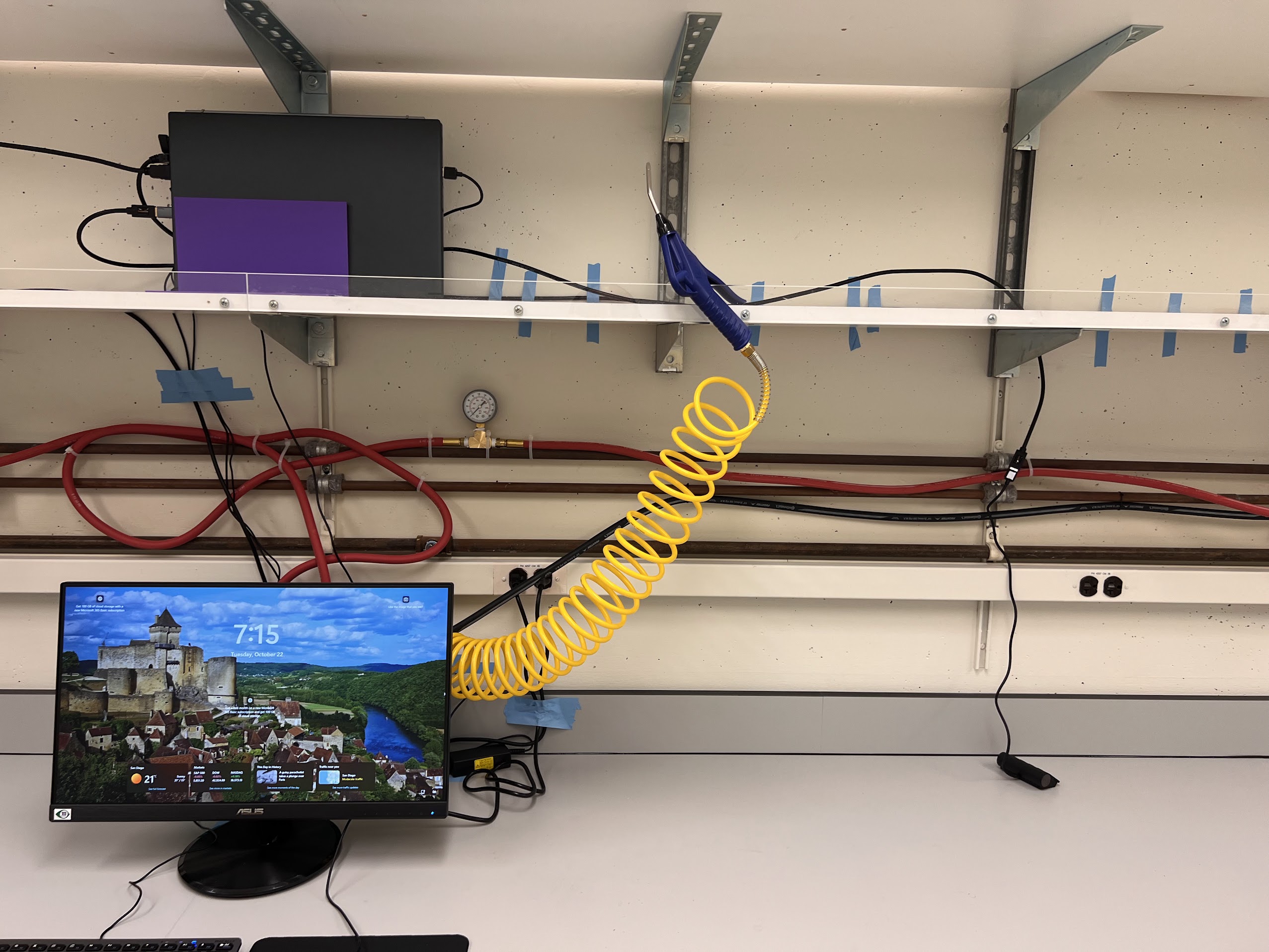
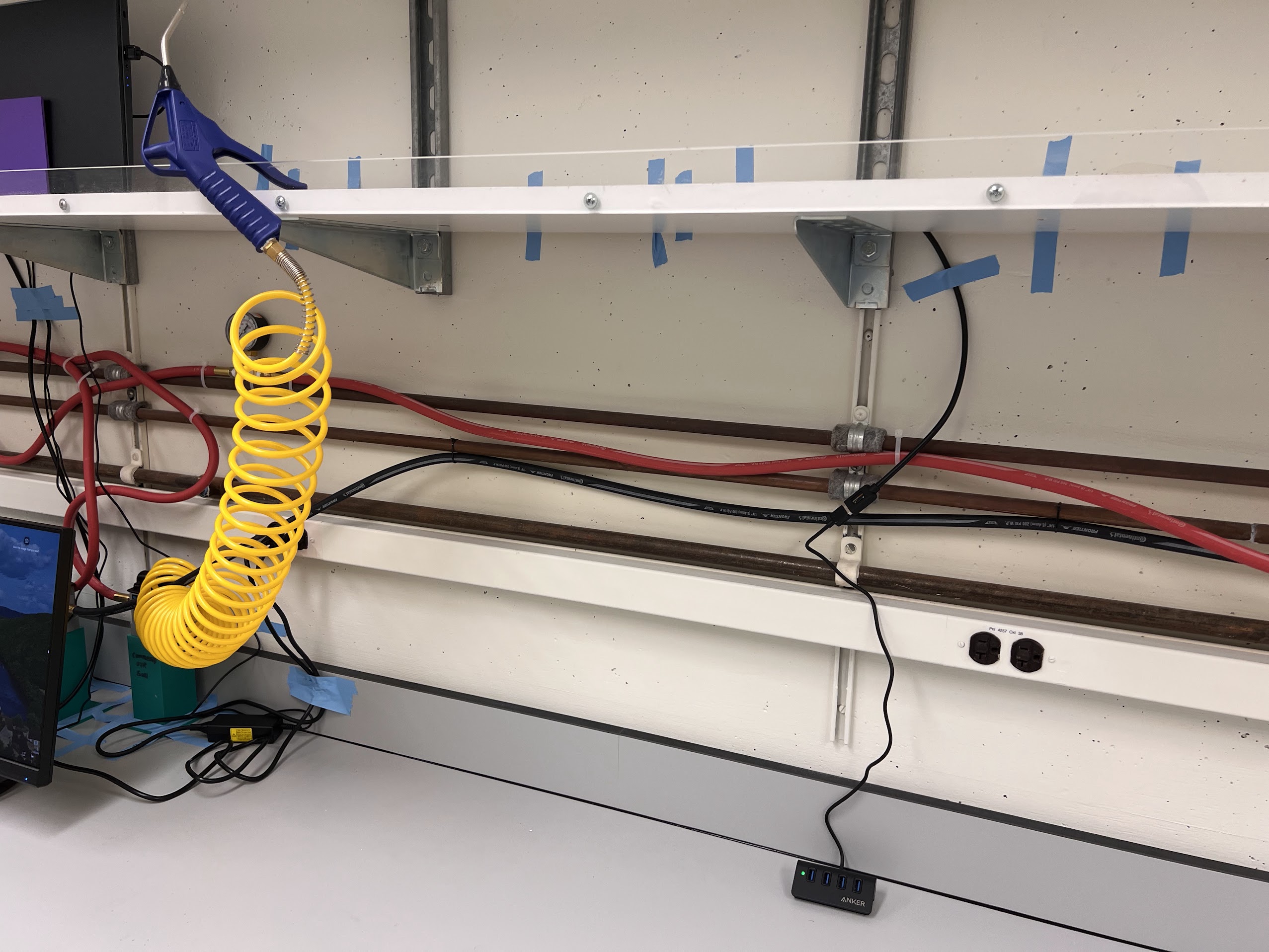
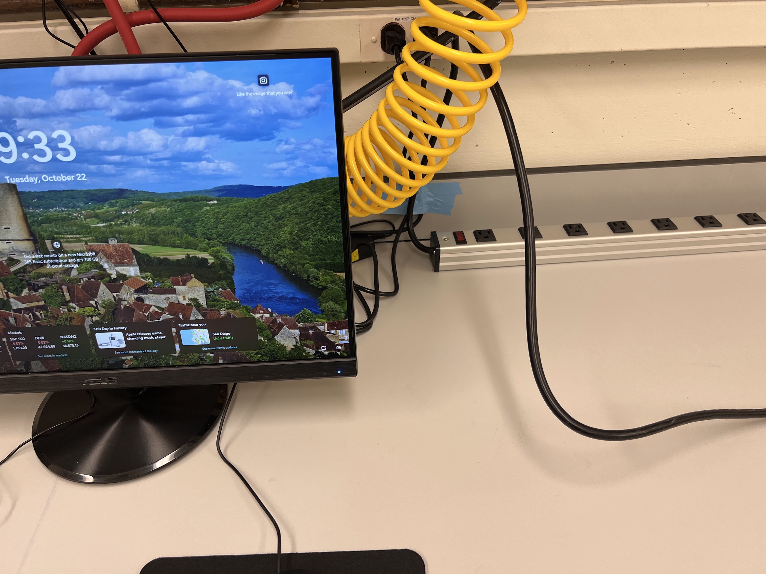
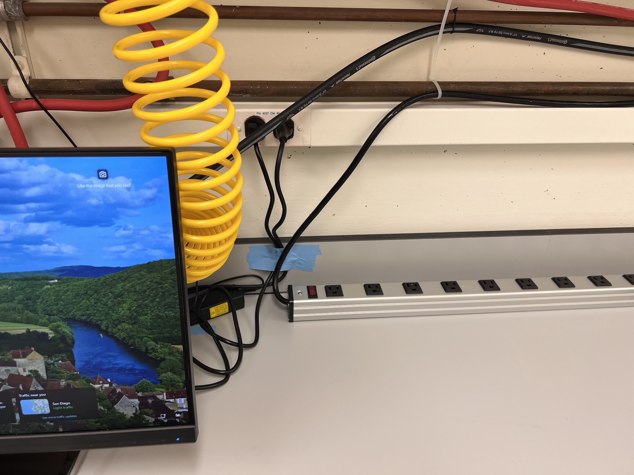
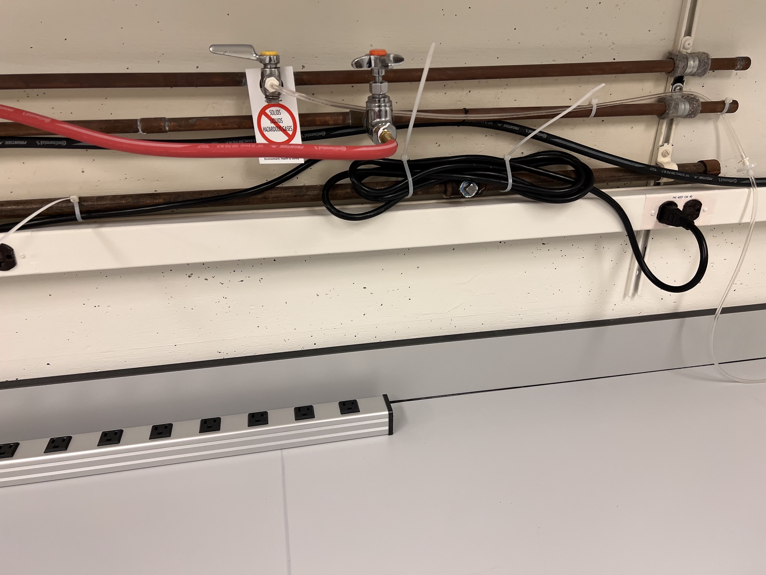
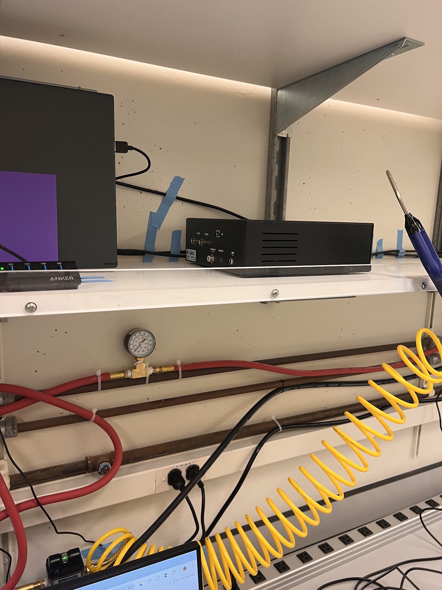
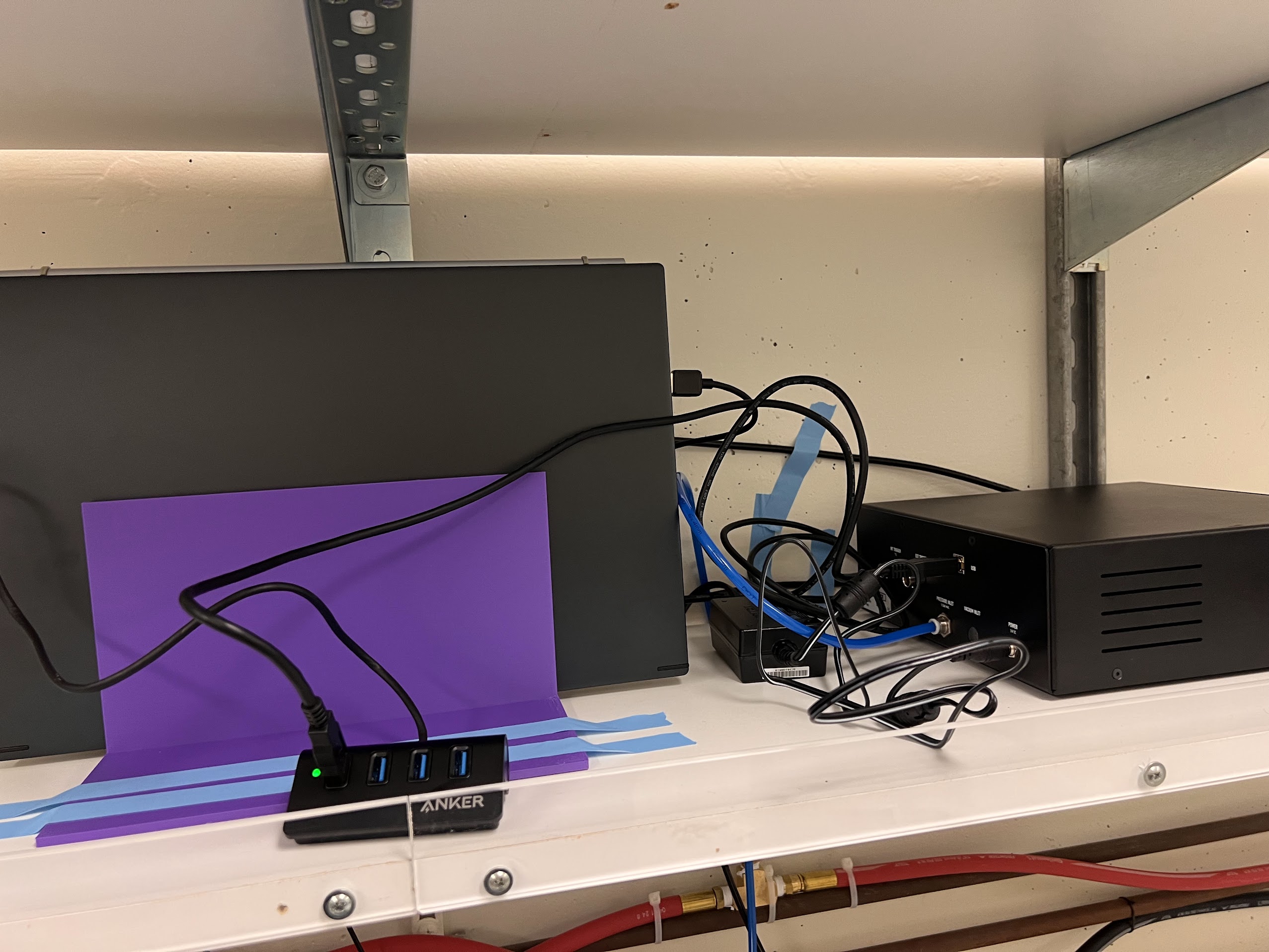
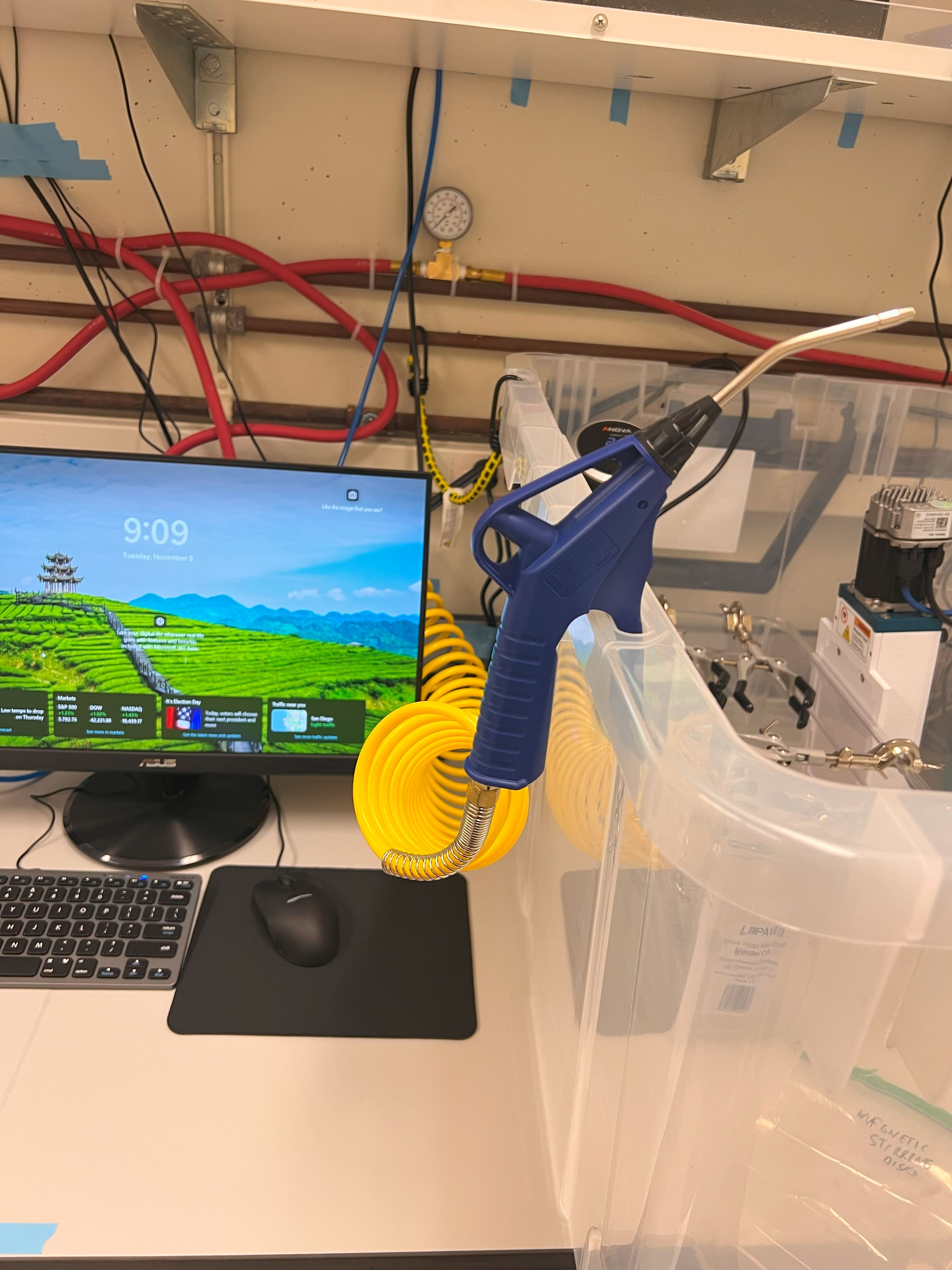
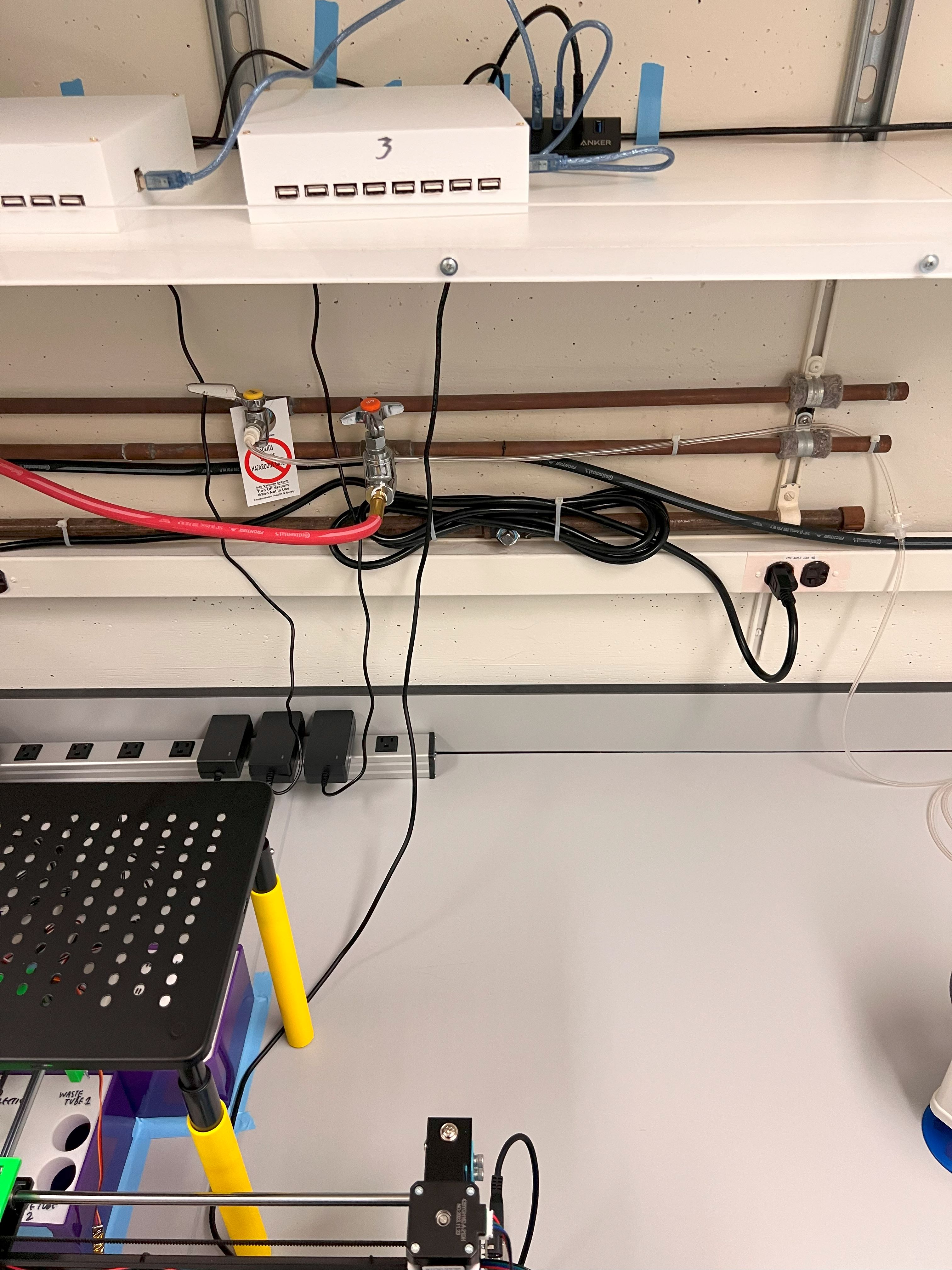
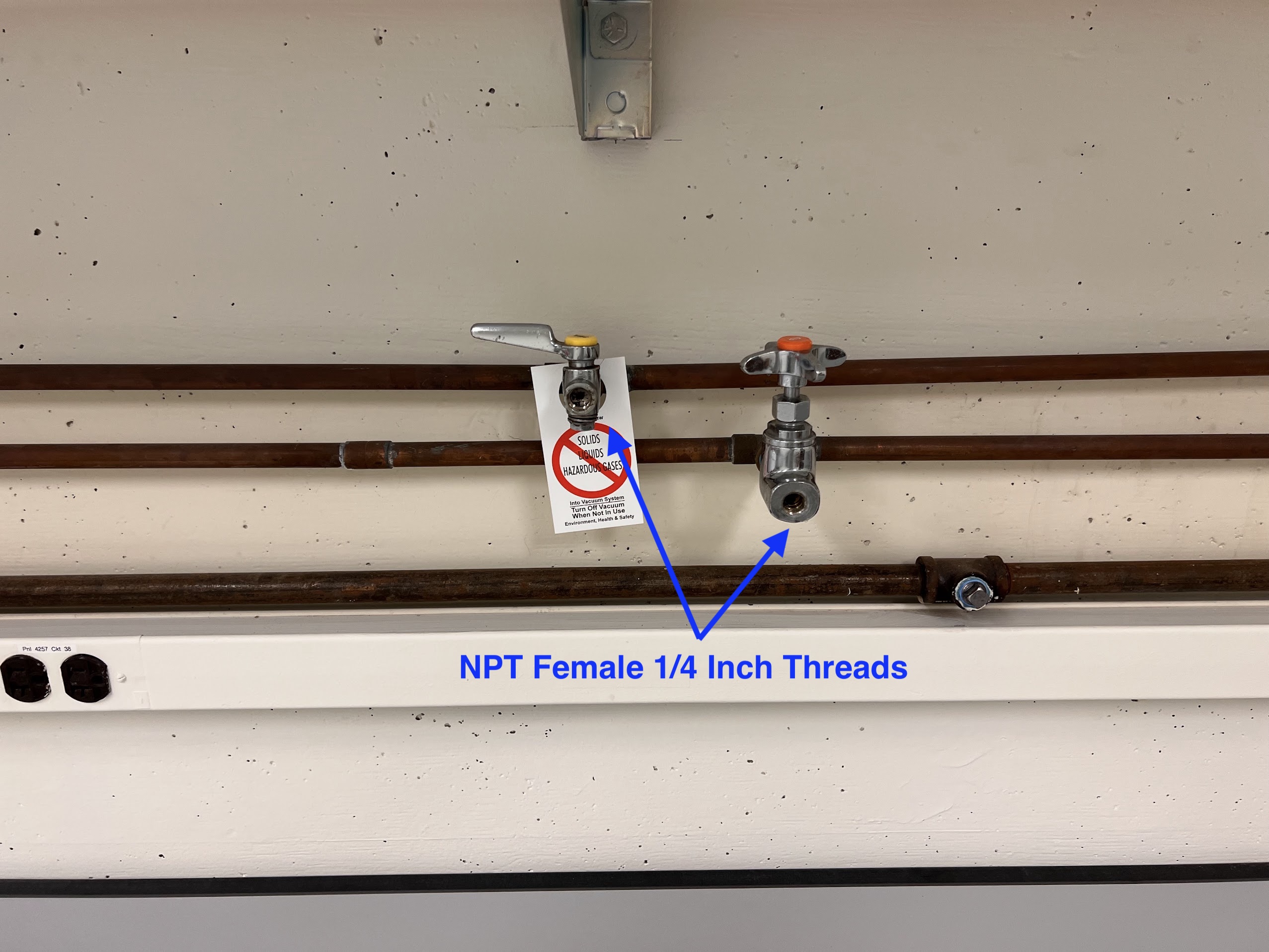
  • The barbs for the House Air and Vacuum sources were also removed. The input threads for sources in our building were Female NPT 1/4 Inch.

  • We had 2 each of Vacuum and House Air sources on our bench as shown.

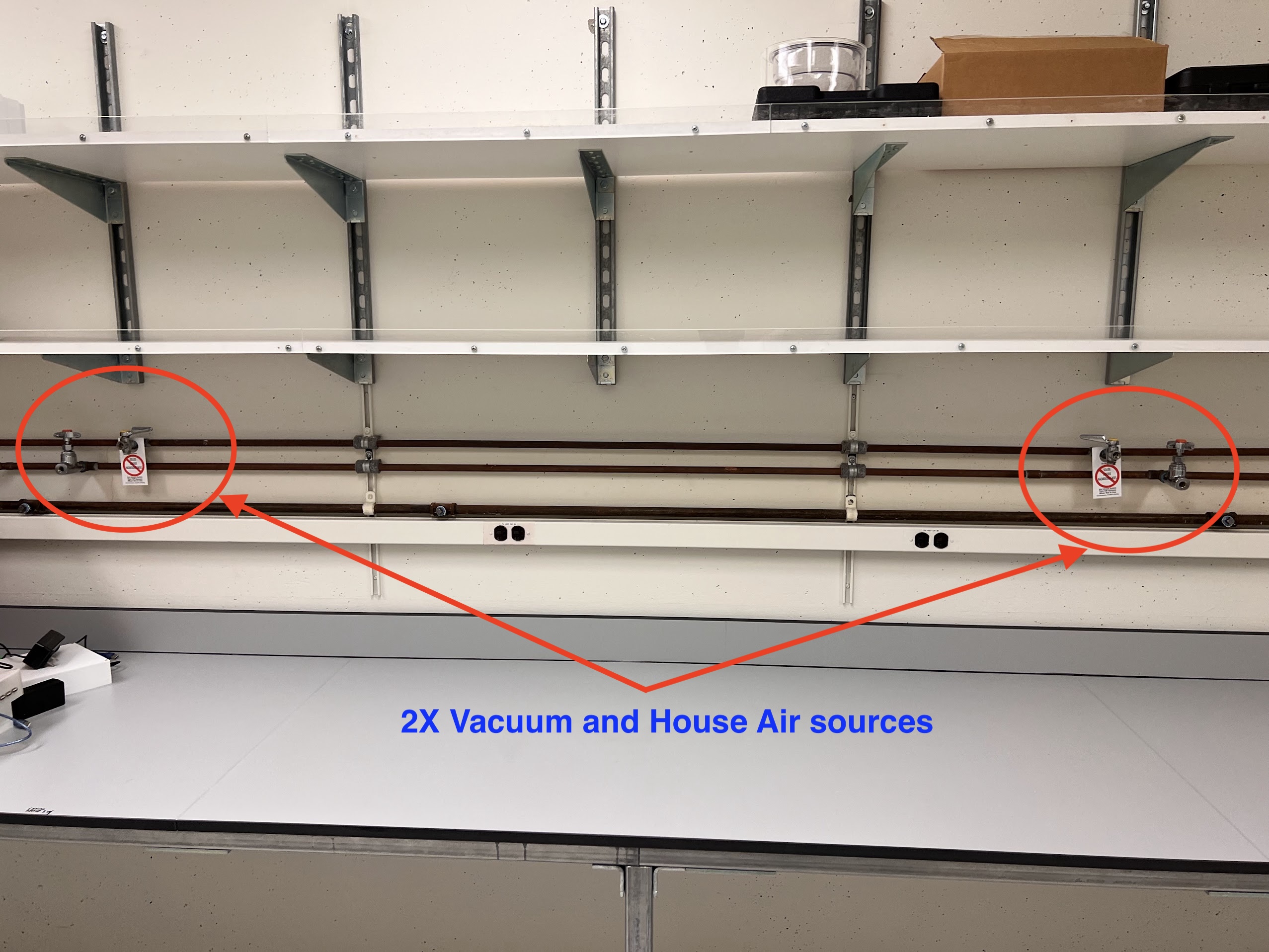
    • We need 2 House Air sources and one Vacuum source for our device.

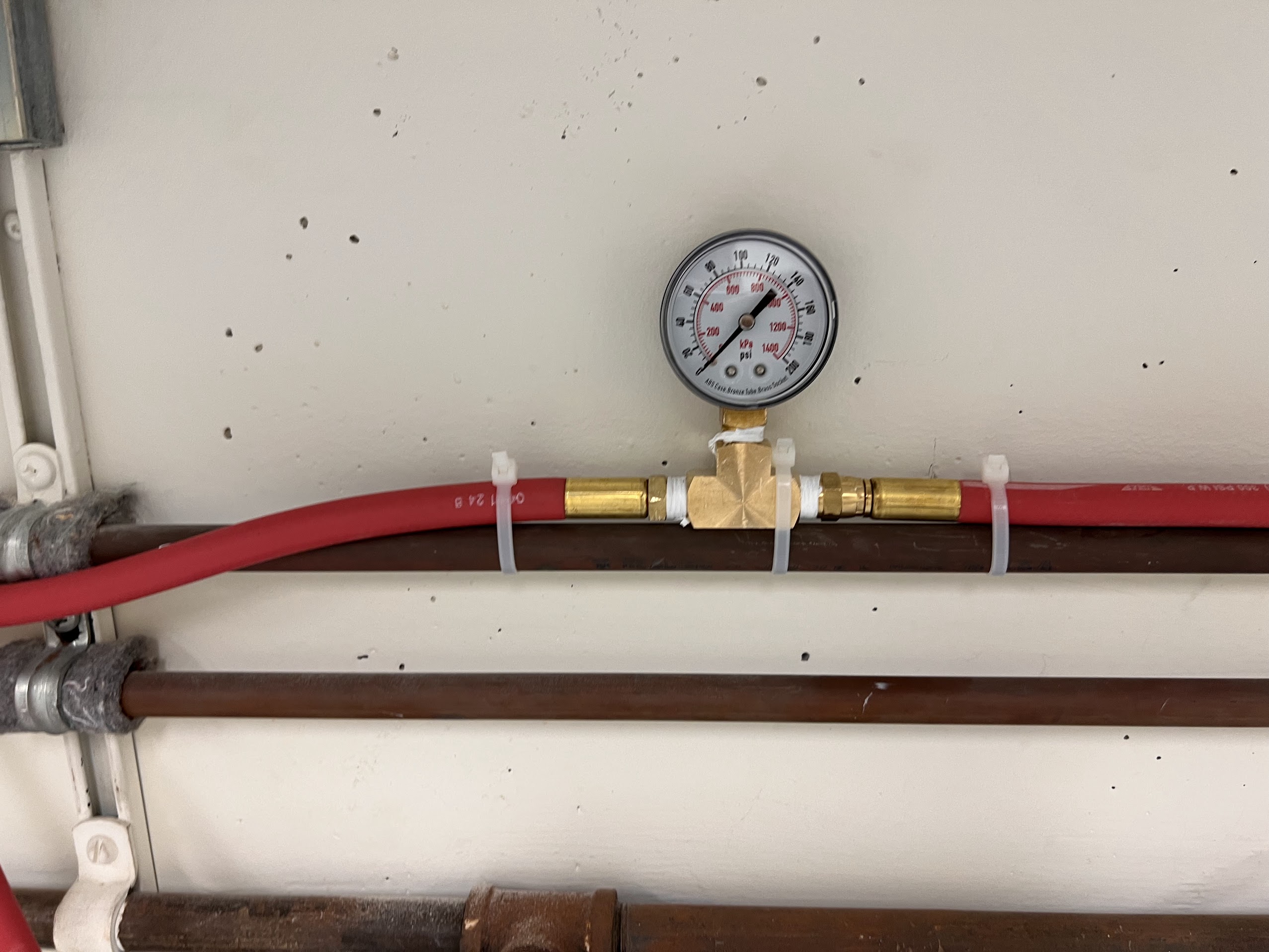
Setting up 5%CO2 Cylinder as Pressure source for ChronoSeq Device

WARNING: Make sure you wear safety glasses. Comressed Air can be dangerous. Please follow the Hazard Control Plans for your lab and institution.

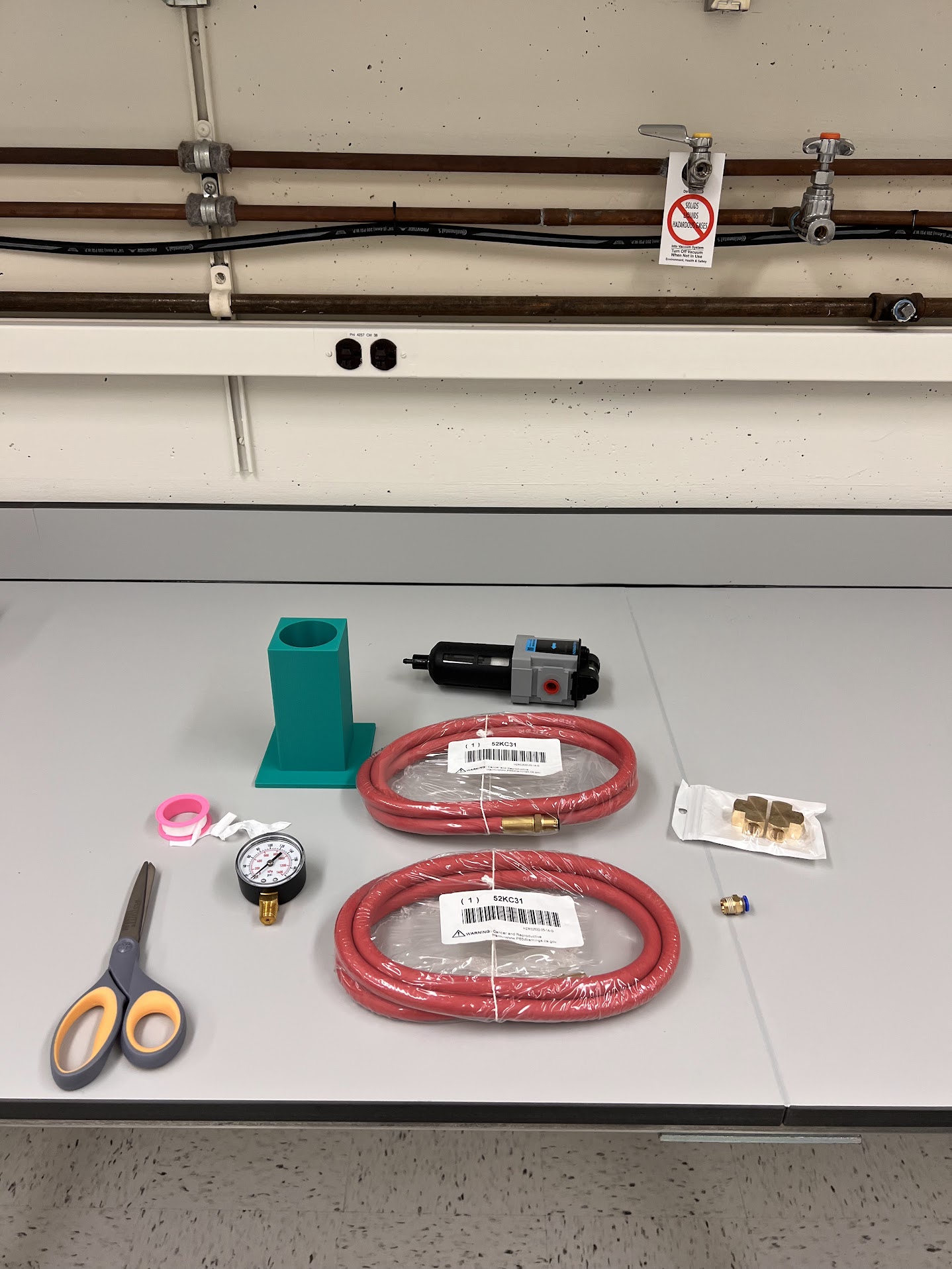
  • You will the following Items:
    • 10 inch Adjustable Wrench
    • 2 Stage Gas Regulator CGA 500
    • Air Hose 50ft 200 PSI Max Pressure
    • 0.5 Micron Coalescing Filter 150PSI Max Pressure
    • Two Pneumatic Connection Kits
    • 6 inch/150mm Adjustable Wrench
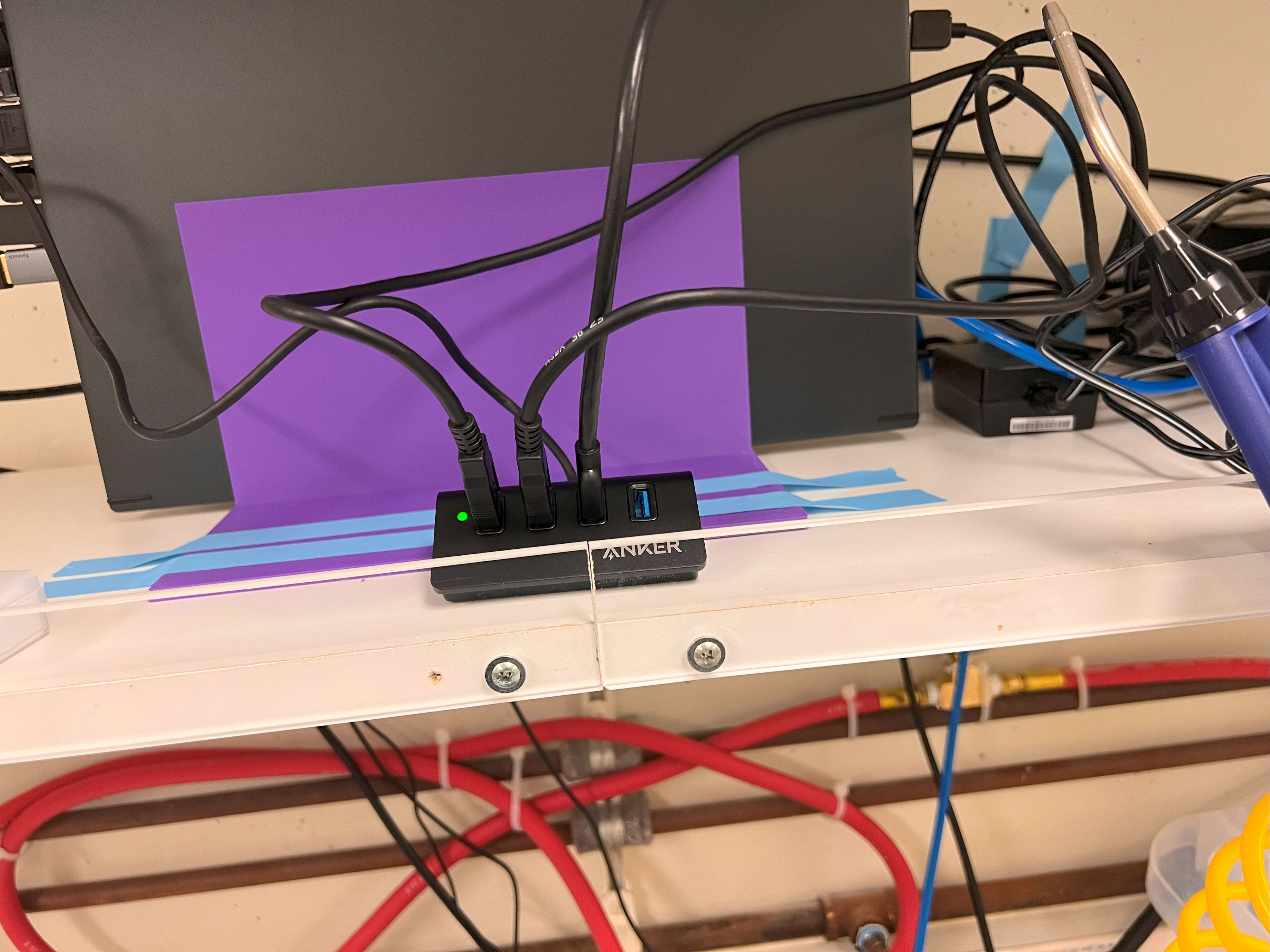
  • Execute the cell below to watch a video on how to connect your Gas Regulator to the cylinder and then set the second stage pressure to 6.5Bars.
In [1]:
%%HTML
<iframe width="800" height="600" src="https://www.youtube.com/embed/npxS9k2oQEg?si=Wmczb_2HpV-5k8vi" title="YouTube video player" frameborder="0" allow="accelerometer; autoplay; clipboard-write; encrypted-media; gyroscope; picture-in-picture; web-share" referrerpolicy="strict-origin-when-cross-origin" allowfullscreen></iframe>
  • Next we will need to connect our regulator to a Filter with a Push connect fitting for Pneumatic Tubing.
  • Execute the cell below to watch a video of the process.
In [2]:
%%HTML
<iframe width="800" height="600" src="https://www.youtube.com/embed/vaCiO843u6A?si=LrUy3pbDrqNDBWHV" title="YouTube video player" frameborder="0" allow="accelerometer; autoplay; clipboard-write; encrypted-media; gyroscope; picture-in-picture; web-share" referrerpolicy="strict-origin-when-cross-origin" allowfullscreen></iframe>
  • Put the filter in the 3D printed stand for it. Then put the filter slightly to the right of the left edge of marked boundary for the ChronoSeq device.
  • You will notice there are many tangles in the Hose/Pipe.
  • Straighten the Hose and Zip Tie as shown below:


  • Use the Zip Ties to Tie the additional length of the Hose to the Right underside of your bench as shown.
  • Secure the Filter holder in place using Labelling Tape. Label the stand as 5% CO2.
  • Next we will check for Leaks.
    • You will need the OB1 Pressure Controller for this step.
    • You don't need to connect the OB1 to power or your computer for this.
    • Please don't disconnect the Pneumatic Tubing when the system is pressurised. This is very dangerous and can lead to injury.
    • Execute the cell below to watch a video of this process.
In [3]:
%%HTML
<iframe width="800" height="600" src="https://www.youtube.com/embed/irPr6I4Sb8A?si=Iop2RGkeZGaKVGCn" title="YouTube video player" frameborder="0" allow="accelerometer; autoplay; clipboard-write; encrypted-media; gyroscope; picture-in-picture; web-share" referrerpolicy="strict-origin-when-cross-origin" allowfullscreen></iframe>

Setting up House Air as Pressure source for ChronoSeq Device

  • You will need the following additional items:
    • Two 5ft Hoses NPT 1/4 inch
    • 0-200 PSI Pressure Gauge
    • 0.5 Micron Coalescing Filter 150PSI Max Pressure
    • Scissors
    • NPT 1/4 inch Female Tee
  • Execute the cell below to watch a video of the setup process and gas leak check.
In [4]:
%%HTML
<iframe width="800" height="600" src="https://www.youtube.com/embed/5q3FdRU-HvI?si=AjSbE3-zBajwQlS6" title="YouTube video player" frameborder="0" allow="accelerometer; autoplay; clipboard-write; encrypted-media; gyroscope; picture-in-picture; web-share" referrerpolicy="strict-origin-when-cross-origin" allowfullscreen></iframe>
  • Use Zip Ties to secure the Hose and Pressure Gauge in place.
  • Cut off the excess Zip Ties.
  • Secure the House Air Filter stand in place using Labelling Tape. Label the Stand as "House Air".
  • We can now have the option to choose between either House Air or 5%CO2 as a pressure source for our device.

Setting up Compressed Air Gun

  • You will need the following items:
    • 5ft Hose NPT 1/4 inch
    • 0.5 Micron Coalescing Filter 150PSI Max Pressure
    • 25ft Coiled Air Hose
    • Air Gun
    • PTFE Tape and Scissors from Pneumatic Connection Kit.
  • Execute the cell below to watch a video of the process for setting up the Compressed Air gun.
In [5]:
%%HTML
<iframe width="800" height="600" src="https://www.youtube.com/embed/GlHhLa7J9-k?si=S44eV6COFLli2M4y" title="YouTube video player" frameborder="0" allow="accelerometer; autoplay; clipboard-write; encrypted-media; gyroscope; picture-in-picture; web-share" referrerpolicy="strict-origin-when-cross-origin" allowfullscreen></iframe>
  • Label the Filter Holder as shown.
  • Use Zip ties to secure the 5ft hose in place.
    • Cut the excess length for the Zip ties. after that.

Setting up Vacuum Line

  • We can use Vacuum to remove melt water from the Ice boxes.
  • However, we don't want liquid going in directly into the Vacuum source.
  • For this purpose we need a way to collect the water in a separate bottle.
  • You will need the following items for this and later steps:
    • Manual On/Off Valve
    • PTFE Tape from Pneumatic Connections Kit
    • Adjustable Wrenches
    • Scissors
    • 200 Units Male Luer Lock to 3/32 Inch Barb Adapter
    • 2 Units of 100ft 3/32 Inch Internal Diameter Soft PVC Tubing: Tygon
    • 30 Units Delrin Plug Flat Bottom 1/4-28
    • 1/4 NPT Male to Luer Adapter
    • Female Luer Lock to 3/32 Inch Barb Adapter
    • 2L GL45 Glass Bottle
    • Tisch Brand SPEC16279 Polytetrafluoroethylene PTFE Syringe Filter, 3um, 25mm, Double luer Lock
    • 3 Port GL45 Cap from VICI Precision Sampling:
      • Product Code: JR-S-11002
      • We emailed Precision Sampling precision@vici.com for a Quote.
      • We paid via Credit Card by providing this information over the phone.
      • Ordered 2 Caps at 41.10 USD Each , October 2024.
  • Execute the cell below to watch a video of the process and rationale for setting up the Vacuum line.
In [6]:
%%HTML
<iframe width="800" height="600" src="https://www.youtube.com/embed/uAPeY82PT_4?si=bTl86-rfipuNgATv" title="YouTube video player" frameborder="0" allow="accelerometer; autoplay; clipboard-write; encrypted-media; gyroscope; picture-in-picture; web-share" referrerpolicy="strict-origin-when-cross-origin" allowfullscreen></iframe>

Assembling Monitor Risers

  • Make sure you remove all the support material for the 3D printed leg extensions.
  • You will need to purchase two Monitor Risers.
  • Here are the parts you will need for installing the 3D printed legs.
    • The Shorter legs are shown in this example, but the process for the Longer legs is exactly the same.
  • Execute the cell below to watch a video of the assembly process.
In [7]:
%%HTML
<iframe width="800" height="600" src="https://www.youtube.com/embed/m67uend2roI?si=g6A1ALqVY39b3Y1i" title="YouTube video player" frameborder="0" allow="accelerometer; autoplay; clipboard-write; encrypted-media; gyroscope; picture-in-picture; web-share" referrerpolicy="strict-origin-when-cross-origin" allowfullscreen></iframe>
  • The one with the longer legs should look like this after assembly.

Assembling the Valve Holders

  • The Top and Bottom Pieces are printed separetly.
  • Push the Top Piece into the Bottom Piece. Make sure the orientation matches the picture below.

Setting up the X86-64Bit Windows Computer

  • See the Computer Selection file for help with Selecting a Computer.
  • Place the 3D printed Stand on the rack above the left most egdge of the marked ChronoSeq device boundary.
  • We place the Laptop Computer in the stand in the following Orientation:
Left Side Right Side
  • DC Power Adapter was connected to our computer.
  • The Adapter was plugged into the nearest power outlet on the Bench.
  • The USB 3 Type C Port was converted to a Type A Port using an Adapter.
  • A Monitor was connected via HDMI to our computer:
    • HDMI cable was routed along the wall behind the monitor.
    • The monitor was plugged into the nearest outlet on the bench.
HDMI Cable Routed along the back Plugged into nearest electrical Outlet
  • Connect a USB Hub to the USB 2 Port on the right.
    • We will use this USB Hub for only our keyboard and mouse.
  • Connect a Keyboard and Mouse to the USB Hub as shown.
    • You will also need a Mouse pad
Keyboard and Mouse Connected to USB Hub for USB 2 Port
  • Move the USB Hub to the left side and secure it in place using some Labelling Tape.
  • Route the HDMI, Keyboard and Mouse Cables behind the 5%CO2 filter for better cable management.
  • Tape these cables to the wall using Labelling Tape.
  • To keep the HDMI Cable taught, tape it to the Bottom of the Rack using Labelling Tape.
  • To prevent the DC Adapter for the Computer from tangling with the Compressed Air Gun Hose, we will also use Labelling Tape as shown.
  • To prevent the Laptop stand from moving, use labelling tape as shown.
  • Make sure the monitor, keyboard and mouse are close to the marked boundary for the ChronoSeq device as shown.
  • Connect a CAT6 Ethernet Cable to the RJ45 Port on the Laptop Computer.
  • Route the cable along the back of the rack above the bench to the nearest Ethernet Port.
  • Secure the Cable to the back of the rack and wall using Labelling Tape as shown.
  • Connect the other side of the cable to the wall Ethernet RJ45 Port.
  • Zip tie and excess cable to the side of your bench as shown.
  • UCSD Only: You might need to activate your ethernet ports and Register your Computer to the Campus Network. Login required.
    • Open CMD and Type >ipconfig/all to get the Hardware(MAC) address for your Ethernet.
    • Follow campus instructions on Connecting Workstations.
    • Use the Campus Service Request form to activate the wall Ethernet ports if not already activated.
  • Now we will setup three USB 3 Hubs for the various components of our ChronoSeq device.
    • You will also need two USB 3 Extension Cables
  • We will connect our first USB Hub to our extension cable and then to our USB Type C Port.
  • Place the USB Hub at the back in the middle of the area designated for the ChronoSeq device.
    • Secure the extension cable with labelling tape.
Place the Hub at back in middle of ChronoSeq device area Connect to the USB 3 Type C Port as shown Secure the Extension cable in place using Labelling Tape
  • We will use an extension cable with the second USB Hub and connect it to our USB 3 A Port.
  • The second USB Hub will be kept on the rack above the bench on the right corner of the area above the ChronoSeq device.
  • Connect the extension cable to the USB 3 Port as shown.
  • Secure the extension cable with labelling tape as shown.


  • The third USB Hub should be directly connected to the USB 3 A port on your computer.
  • This picture shows the positions of all three hubs.
  • Make sure you use Nitrile Gloves when using the Keyboard and Mouse for your Computer after you have assembled the device.
    • Leave a note to remind yourself.

Setting up Power Strip

  • We used a 20 Outlet Power Strip for powering all major ChronoSeq device Components.
    • This way we could switch the device on and off with a single switch on the power strip.
  • Place the power strip at the back of your bench with the switch positioned close behind the right side of the monitor.
Put the power strip at the back of your bench The On/Off switch should be close to the right side of the monitor for easy access
  • Use Zip Ties to secure the extension cord as shown.
    • Fold the extra extension cord out of the way as shown.
    • Plug in the power stip into an outlet on your bench.


  • Cut off excess length of the Zip Ties.

Software Installation

  • I recommend going to Display Setting on your Windows PC and setting the Scale to 125%
  • Please download the Elveflow Software and SDK.
    • The version compatible with your Elveflow Instruments should come in a USB Drive with your instruments.
    • For our hardware we had ESI_V3_07_02
  • Extract the file. Right Click and Select: Extract All
  • Go to the ESI folder and run setup.exe.
  • Also Extract the SDK Folder.
  • Go to "Installx64\Extra Install For x64 Libraries" Folder and run setup.exe.
  • Copy the DLL64 Directory from the SDK Directory.
  • Paste the DLL64 Directory into your config folder.
    • Everything inside the config folder is ignored by git unless already included in the repository.
    • Make sure you make regular Backups of your config folder or store the repository in OneDrive/Google-Drive so its automatically backed up.
    • The config folder is specific to each ChronoSeq device as it contains device specific information.
  • Execute the cells below and allow python to connect to local network if the dialog box comes up.
  • Change your PC's power setting to make sure:
    • Computer is set to maximum performance.
    • Computer never sleeps.
    • Display is never turned off.
    • Disable Screen saver.
    • Computer never hibernates.
  • Newer Windows PCs more security features such as TPM.
    • Disable TPM and other security features in the BIOS menu.
    • These security features might randomly crash the Python Kernel.
    • Here is an image of the disabled security feature in our BIOS Menu.
      • For Dell you can enter the BIOS Setup menu by repeatedly pressing F12 when the computer is booting.
  • Its also a good idea to make sure your Notebook is Trusted.
    • Click on "Not Trusted" before you get started if you see it next to the Python Kernel indicator.
In [8]:
# coding : utf8
%matplotlib inline
import os
import sys
sys.path.append(os.getcwd());
import ivPID.PID as PID_controller

print(os.getcwd())
os.chdir(".\config")

#Adding required directories to sys.path. Make sure you are in the Directory with the Git Repo when you start Jupyter Notebook
sys.path.append(os.getcwd());
sys.path.append(os.getcwd()+"\\DLL64");

import time
import Elveflow64
os.chdir("..")
from ctypes import *
import numpy as np
import matplotlib.pyplot as plt
import pandas as pd
import serial
import threading
from apscheduler.schedulers.background import BackgroundScheduler
from apscheduler.schedulers import SchedulerNotRunningError
from datetime import datetime,timedelta
import seaborn as sns
import pygame
C:\Users\kanis\Documents\ChronoSeq
pygame 2.5.2 (SDL 2.28.3, Python 3.7.16)
Hello from the pygame community. https://www.pygame.org/contribute.html
In [9]:
%%javascript
IPython.OutputArea.prototype._should_scroll = function(lines) {
    return false;
}

Note on Ipython Magics

  • We will store device specific configuration in the config folder using Ipython Magics
  • We modified the %%writefile magic as follows.
  • Execute the cell below
In [10]:
from IPython.core.magic import register_cell_magic

@register_cell_magic
def write_and_run(line, cell):
    argz = line.split()
    file = argz[-1]
    mode = 'w'
    if len(argz) == 2 and argz[0] == '-a':
        mode = 'a'
    with open(file, mode) as f:
        f.write(cell)
    get_ipython().run_cell(cell)

Setting up the Pressure Controller

  • We now need to connect our pressure controller to our computer and power.
  • We need to also cut some Pneumatic tubing and connect it to House air.
    • You will need to following:
      • Pneumatic Tubing from Pneumatic Connections Kit
      • Tubing Cutter from Pneumatic Connections Kit
      • USB 2.0 Type A to Type B Extension Cable
      • AC Power Cable
      • OB1 Pressure Controller
  • We will also need to use Luer plugs to block the three independent pressure channels for Calibration.
  • Execute the cell below to watch a video of the process.
In [11]:
%%HTML
<iframe width="800" height="600" src="https://www.youtube.com/embed/vY6V0Eq87n8?si=x5sQQwJoQZgS2SXT" title="YouTube video player" frameborder="0" allow="accelerometer; autoplay; clipboard-write; encrypted-media; gyroscope; picture-in-picture; web-share" referrerpolicy="strict-origin-when-cross-origin" allowfullscreen></iframe>

Getting Serial Number for pressure controller from NI Max

  • We now need the serial number for our OB1 Pressure controller so we can control it using Jupyter Notebooks.
  • We will also have to run the Elveflow Smart Interface once before getting started.
  • Execute the Cell Below to watch a video of the process.
    • Make sure you have your Safety Glasses on before turning on the House Air Pressure.
In [12]:
%%HTML
<iframe width="800" height="600" src="https://www.youtube.com/embed/DC1oscWOHng?si=fX7POu0JLhZYOXPn" title="YouTube video player" frameborder="0" allow="accelerometer; autoplay; clipboard-write; encrypted-media; gyroscope; picture-in-picture; web-share" referrerpolicy="strict-origin-when-cross-origin" allowfullscreen></iframe>
  • Now paste the value for the Serial number in the cell below.
  • We will store the device initialization information in the config/instrument_initialization.py file.
In [13]:
%%write_and_run config/instrument_initialization.py
OB1_pressureControllerCOM="020B9F6C" #Serial Number from NI MAX Paste Here

#Initializing Pressure Controller
pressureController=c_int32()
error=Elveflow64.OB1_Initialization(OB1_pressureControllerCOM.encode('ascii'),2,2,2,0,byref(pressureController)) 
if(error==0):
    print("Pressure Controller Connection Started")
    print('Pressure Controller ID: %d' % pressureController.value)
else: 
    print("error %d :" % error)

#Defining Channel Bindings according to current configuration
cell_channel=1
oil_channel=2
bead_channel=3
Pressure Controller Connection Started
Pressure Controller ID: 0
  • Now we will calibrate our OB1 Pressure Controller.
  • Make sure the three pressure channels are plugged using the Luer plugs.
  • Execute the cell below to begin the calibration.
    • The calibration file will be stored in the config folder.
    • This may take upto 10 minutes for the first time. Please be patient.
    • The OB1 Display should show that it is Calibrating.
In [14]:
%%write_and_run config/pressure_controller_load_calibration_file.py
#Make sure you Calibrate with the plugs in place if you are generating the file for the first time.
#See OB1 user manual for details about calibration and the plug type to use.
calibrationVector=(c_double*1000)()
currentWorkingDirectory=os.getcwd()
calibrationFilePath=currentWorkingDirectory + "\\config\OB1_CalibrationFile.txt"
fileExists=os.path.isfile(calibrationFilePath)

if(fileExists):
    error=Elveflow64.Elveflow_Calibration_Load(calibrationFilePath.encode('ascii'), byref(calibrationVector), 1000)
    if(error==0):
        print("Calibration File Load Successful!")
    else:
        print("error %d :" % error)

else:
    Elveflow64.OB1_Calib(pressureController.value, calibrationVector, 1000)
    error=Elveflow64.Elveflow_Calibration_Save(calibrationFilePath.encode('ascii'), byref(calibrationVector), 1000)
    if(error==0):    
        print('Calibration saved in %s' % calibrationFilePath)
    else:
        print("error %d :" % error)
Calibration File Load Successful!
In [15]:
def set_oil_channel_pressure(oil_channel_pressure):
    Elveflow64.OB1_Set_Press(pressureController.value,c_int32(oil_channel),c_double(oil_channel_pressure),byref(calibrationVector),len(calibrationVector))
    
def get_oil_channel_pressure():
    getOilChannelPressure=c_double()
    Elveflow64.OB1_Get_Press(pressureController.value,c_int32(oil_channel),1,byref(calibrationVector),byref(getOilChannelPressure),len(calibrationVector)) 
    return getOilChannelPressure.value

def set_cell_channel_pressure(cell_channel_pressure):
    Elveflow64.OB1_Set_Press(pressureController.value,c_int32(cell_channel),c_double(cell_channel_pressure),byref(calibrationVector),len(calibrationVector))

def get_cell_channel_pressure():
    getCellChannelPressure=c_double()
    Elveflow64.OB1_Get_Press(pressureController.value,c_int32(cell_channel),1,byref(calibrationVector),byref(getCellChannelPressure),len(calibrationVector))
    return getCellChannelPressure.value

def set_bead_channel_pressure(bead_channel_pressure):
    Elveflow64.OB1_Set_Press(pressureController.value,c_int32(bead_channel),c_double(bead_channel_pressure),byref(calibrationVector),len(calibrationVector))
    
def get_bead_channel_pressure():
    getBeadChannelPressure=c_double()
    Elveflow64.OB1_Get_Press(pressureController.value,c_int32(bead_channel),1,byref(calibrationVector),byref(getBeadChannelPressure),len(calibrationVector)) 
    return getBeadChannelPressure.value

def reset_pressures():
    set_cell_channel_pressure(get_cell_channel_pressure())
    set_bead_channel_pressure(get_bead_channel_pressure())
    set_oil_channel_pressure(get_oil_channel_pressure())
  • Now lets try controlling our pressure controller using these python functions.
  • Keep all three ports blocked.
  • Execute the cell below. You will hear the three channels pressurize and then depressurize.
In [16]:
time.sleep(5)
set_cell_channel_pressure(2000)
set_bead_channel_pressure(2000)
set_oil_channel_pressure(2000)
time.sleep(5)
set_cell_channel_pressure(0)
set_bead_channel_pressure(0)
set_oil_channel_pressure(0)
  • Now Turn off the House Air Pressure.
  • Execute the cell below to close the connection to the Pressure Controller.
  • We will store this code in config/deviceShutdown.py
In [17]:
%%write_and_run config/deviceShutdown.py
error=Elveflow64.OB1_Destructor(pressureController.value)
if(error==0):
    print("Pressure Controller Connection Closed!")
else:
    print("error %d :" % error)
Pressure Controller Connection Closed!
  • After the System is depressurized we can move our Pressure Controller to its final position.
  • Disconnect the Pneumatic Tubing
  • Turn off the Power Strip.
  • Disconnect the USB
  • Place the Pressure Controller on the rack next to your Computer as shown.
  • Reconnect:
    • The USB Cable to the USB Hub next to your Computer.
    • and Route the AC Power Extension cord through the back to the power strip.
    • and Route the Pneumatic Tubing through the back.

Setting up Valve Controllers

  • You will need a USB 2.0 Type A to Type B Extension cable.
  • We will connect and Place the three Valve Controllers you made on the rack above the bench as shown.
    • Route the DC Power cable from the back to the Power Strip.
  • Mark the Valve Controllers as 1, 2 and 3 with a marker as shown.
  • Using the USB 2.0 Type A to Type B Extension cable connect the Valve Controller 1 to USB Hub next to the Computer.
  • Identify the COM Port for Valve Controller 1 using the Arduino IDE.
    • For our machine it was COM3
  • Using the USB 2.0 Type A to Type B cable included with Elegoo UNO R3 connect the Valve Controller 2 to the USB Hub on rack towards the right.
  • Identify the COM Port for Valve Controller 2 using the Arduino IDE.
    • For our machine it was COM4
  • Using the USB 2.0 Type A to Type B cable included with Elegoo UNO R3 connect the Valve Controller 3 to the USB Hub on rack towards the right.
  • Identify the COM Port for Valve Controller 3 using the Arduino IDE.
    • For our machine it was COM5
  • Now we will intiate a Serial connection to our Valve Controllers.
    • Populate the Variables below with the COM Port values from Arduino IDE
  • Execute the cell below to initialize the connection to the Valve Controllers.
    • We will append the config/instrument_initialization.py file.
In [18]:
%%write_and_run -a config/instrument_initialization.py
firstControllerCOM="COM3"  #COM Port from Arduino IDE
secondControllerCOM="COM4" #COM Port from Arduino IDE
thirdControllerCOM="COM5"  #COM Port from Arduino IDE

#Initializing Valve Controllers
valve_controller1=c_int32()
valve_controller1.value=1111

firstController=serial.Serial(firstControllerCOM, timeout=1, write_timeout=0)
time.sleep(5.0)
print(firstController.is_open)
print(firstController.get_settings())


valve_controller2=c_int32()
valve_controller2.value=2222#Assigning some number for third valve controller

secondController=serial.Serial(secondControllerCOM, timeout=1, write_timeout=0)
time.sleep(5.0)
print(secondController.is_open)
print(secondController.get_settings())


valve_controller3=c_int32()
valve_controller3.value=3333#Assigning some number for third valve controller

thirdController=serial.Serial(thirdControllerCOM, timeout=1, write_timeout=0)
time.sleep(5.0)
print(thirdController.is_open)
print(thirdController.get_settings())
True
{'baudrate': 9600, 'bytesize': 8, 'parity': 'N', 'stopbits': 1, 'xonxoff': False, 'dsrdtr': False, 'rtscts': False, 'timeout': 1, 'write_timeout': 0, 'inter_byte_timeout': None}
True
{'baudrate': 9600, 'bytesize': 8, 'parity': 'N', 'stopbits': 1, 'xonxoff': False, 'dsrdtr': False, 'rtscts': False, 'timeout': 1, 'write_timeout': 0, 'inter_byte_timeout': None}
True
{'baudrate': 9600, 'bytesize': 8, 'parity': 'N', 'stopbits': 1, 'xonxoff': False, 'dsrdtr': False, 'rtscts': False, 'timeout': 1, 'write_timeout': 0, 'inter_byte_timeout': None}
  • Next we will define the functions for setting the state of the Valves using the valve controllers.
  • We will store the code for setting the valve in the file config/setValveControllers.py
In [19]:
%%write_and_run config/setValveControllers.py
#Creating a ctypes vector to store the valve states 
#Zero based indexing used. So first valve state is at index 0
valveController1_state=(c_int32*8)(0)
valveController2_state=(c_int32*8)(0)
valveController3_state=(c_int32*8)(0)

def set_first_controller(state_vector):
    stringVector=""
    readString=""
    for digit in state_vector:
        stringVector+=str(digit)
    stringVector+="\n"
    firstController.write(stringVector.encode())
    try:
        readString=firstController.readline().decode("utf-8").strip()
        if readString==stringVector.strip():
            print("Valve Controller 1 State successfully changed!")
            print_array(state_vector)
        else:
            print("Valve Controller 1 Strings don't match. There is a problem!")
            print("Read String is: ",readString)
    except Exception as e:
        print("Valve Controller 1 Serial Read Error. Will Try again!")
        print("Reseting Pressures!")
        reset_pressures()
        set_first_controller(state_vector)
        
def set_second_controller(state_vector):
    stringVector=""
    readString=""
    for digit in state_vector:
        stringVector+=str(digit)
    stringVector+="\n"
    secondController.write(stringVector.encode())
    try:
        readString=secondController.readline().decode("utf-8").strip()
        if readString==stringVector.strip():
            print("Valve Controller 2 State successfully changed!")
            print_array(state_vector)
        else:
            print("Valve Controller 2 Strings don't match. There is a problem!")
            print("Read String is: ",readString)
    except Exception as e:
        print("Valve Controller 2 Serial Read Error. Will Try again!")
        print("Reseting Pressures!")
        reset_pressures()
        set_second_controller(state_vector)

def set_third_controller(state_vector):
    stringVector=""
    readString=""
    for digit in state_vector:
        stringVector+=str(digit)
    stringVector+="\n"
    thirdController.write(stringVector.encode())
    try:
        readString=thirdController.readline().decode("utf-8").strip()
        if readString==stringVector.strip():
            print("Valve Controller 3 State successfully changed!")
            print_array(state_vector)
        else:
            print("Valve Controller 3 Strings don't match. There is a problem!")
            print("Read String is: ",readString)
    except Exception as e:
        print("Valve Controller 3 Serial Read Error. Will Try again!")
        print("Reseting Pressures!")
        reset_pressures()
        set_third_controller(state_vector)

#Defining function to print out all valve states
def print_array(int_array):
    for i in range(0,len(int_array)):
        print(int_array[i], end= " ")
    print("")

#Defining functions to set valves to a specific state 

#WARNING! Only use the safe alternatives of these functions defined below
def set_valves(Instr_ID,state_vector):
    if Instr_ID is valve_controller1:
        set_first_controller(state_vector)
    elif Instr_ID is valve_controller2:
        set_second_controller(state_vector)
    elif Instr_ID is valve_controller3:
        set_third_controller(state_vector)        
        
#Use safe alternative defined below
def close_all_valves(Instr_ID,state_vector):
    for i in range(0,len(state_vector)):
        state_vector[i]=0
    set_valves(Instr_ID,state_vector)
    
def reset_state_vector(state_vector):
    for i in range(0,len(state_vector)):
        state_vector[i]=0
        
def reset_all_state_vectors():
    reset_state_vector(valveController1_state)
    reset_state_vector(valveController2_state)
    reset_state_vector(valveController3_state)

## Need Load File
def update_valve_states():
    set_valves(valve_controller1,valveController1_state)
    set_valves(valve_controller2,valveController2_state)
    set_valves(valve_controller3,valveController3_state)

def reset_valve_states():
    close_all_valves(valve_controller1,valveController1_state)
    close_all_valves(valve_controller2,valveController2_state)
    close_all_valves(valve_controller3,valveController3_state)
  • Now lets try setting the Valve Controllers
  • We will do this by changing the State Vectors and then updating the valve states.
In [20]:
#Turning on the first Valve for all three Controllers
valveController1_state[0]=1
valveController2_state[0]=1
valveController3_state[0]=1
update_valve_states()
time.sleep(5)
Valve Controller 1 State successfully changed!
1 0 0 0 0 0 0 0 
Valve Controller 2 State successfully changed!
1 0 0 0 0 0 0 0 
Valve Controller 3 State successfully changed!
1 0 0 0 0 0 0 0 
  • We can reset the controllers as well
In [21]:
reset_valve_states()
Valve Controller 1 State successfully changed!
0 0 0 0 0 0 0 0 
Valve Controller 2 State successfully changed!
0 0 0 0 0 0 0 0 
Valve Controller 3 State successfully changed!
0 0 0 0 0 0 0 0 
  • Now lets close the connection to our Valve Controllers.
  • We will append the config/deviceShutdown.py file.
In [22]:
%%write_and_run -a config/deviceShutdown.py

firstController.close()
if not firstController.isOpen():
    print("Valve Controller 1 Connection Closed!")
else:
    print("error! Count not close Valve Controller 1 connection.")

secondController.close()
if not secondController.isOpen():
    print("Valve Controller 2 Connection Closed!")
else:
    print("error! Count not close Valve Controller 2 connection.")

thirdController.close()
if not thirdController.isOpen():
    print("Valve Controller 3 Connection Closed!")
else:
    print("error! Count not close Valve Controller 3 connection.")
Valve Controller 1 Connection Closed!
Valve Controller 2 Connection Closed!
Valve Controller 3 Connection Closed!

Setting up Magnetic Stirrer

  • We will setup the V&P Scientific Computer Controlled Magnetic Stirrer.
  • Connect the Provided Data and Power Cables from the Black Controller Box to the Magnetic Stirrer as shown.
  • Connect to the nearest USB Hub using the provided USB Cable.
  • Connect to the Power Strip using the provided AC Power Cable.
  • We will now connect and test the Magnetic Stirrer. You will need:
    • 24mm PVDF Magnetic Stirring Disc for 50ml Tubes from V&P Scientific
    • 50ml Falcon Tubes
    • 3D Printed 50ml Falcon Tube Holder.
  • Add some tap water and magnetic disc to the 50ml Falcon Tube.
  • Using Arduino IDE identify the COM Port for the Magnetic Stirrer.
    • In our case it was COM12
  • Execute the cell below to initialize the Magnetic Stirrer.
    • This will also update the config/instrument_initialization.py file.
In [23]:
%%write_and_run -a config/instrument_initialization.py

magneticStirrerCOM="COM12" #Using Arduino IDE
#Initializing magnetic stirrer
ser = serial.Serial(magneticStirrerCOM, timeout=1, write_timeout=0)
time.sleep(5)
print(ser.name)
print(ser.get_settings())
print(ser.is_open)
if not ser.is_open:
    ser.open()
    time.sleep(5)
COM12
{'baudrate': 9600, 'bytesize': 8, 'parity': 'N', 'stopbits': 1, 'xonxoff': False, 'dsrdtr': False, 'rtscts': False, 'timeout': 1, 'write_timeout': 0, 'inter_byte_timeout': None}
True
  • Now we will try controlling the magnetic stirrer using Jupyter Notebooks.
    • Execute the cell below to watch a video of the process.
    • After which you can execute the cells after the video.
In [24]:
%%HTML
<iframe width="800" height="600" src="https://www.youtube.com/embed/ff7pH2Nusm0?si=6UPNB0Qf3a2jlYut" title="YouTube video player" frameborder="0" allow="accelerometer; autoplay; clipboard-write; encrypted-media; gyroscope; picture-in-picture; web-share" referrerpolicy="strict-origin-when-cross-origin" allowfullscreen></iframe>
In [25]:
#Sets stirrer speed in rpm units
def set_stirrer_speed(rpm):
    buffer=ser.read(ser.inWaiting())
    byteString="s "+str(rpm)
    ser.write(byteString.encode())
    
def stop_stirrer():
    set_stirrer_speed(0)
In [26]:
set_stirrer_speed(200)
time.sleep(10)
In [27]:
stop_stirrer()
  • Execute the cell below to close the connection to the Magnetic Stirrer.
    • This will also update the config/deviceShutdown.py file.
In [28]:
%%write_and_run -a config/deviceShutdown.py

def shutdown_stirrer():
    buffer=ser.read(ser.inWaiting())
    byteString="s "+str(0)
    ser.write(byteString.encode())
    ser.close()
    if not ser.is_open:
        print("Magnetic Stirrer Connection Closed!")

shutdown_stirrer()
Magnetic Stirrer Connection Closed!
  • Turn off the Power Strip.
  • We will use a 160QT Sterlite Storage Container as a Secondary Container for our water bath.
  • Place this Sterlite Container close to the Computer on the left edge of the Power Strip as shown.
  • Put a 19QT Water Bath inside the Sterlite Container.
    • Also put the Magnetic Stirrer next to the Water Bath as shown.
  • Put the Black Magnetic Stirrer Contoller on the rack above your bench as shown.
    • Route the AC Power Cable from the back into the Power Strip.
  • Connect the USB Cable for the Magnetic Stirrer Controller to the USB Hub Next to your Computer.

Setting up the Water Bath

  • We bought a 800W Anova Sous Vide Temperature Controller.
  • We attached it to our Water Bath in the Position Shown.
    • We plugged in the Temperature Controller to the Power Strip.
  • We turned the Power Strip On.
  • Using the Anova App we changed the Temperature Unit for the Sous Vide Temperature Controller to Celcius.
    • We then set the target Temperature to 37°C.
  • Attach five 3-Finger Clamps on the water bath as shown.
    • We will use these clamps to hold 50ml Falcon Tubes for the Cell Channel in the water bath.
    • Make sure the Magnetic Stirrer is right next to the Holding location for the Top right Clamp.
  • (Optional) Since UC San Diego is in an earthquake zone we also secured the Sterlite Container with Bungee Cords as shown.


  • Remove and dry the Magnetic Stirring Disk from the 50ml Tube.
    • Then put it in a Ziploc Pouch.
    • You can keep the other Magnetic Stirring Disks in this pouch as well.
  • Put this pouch in the Sterlite Container as shown, for future use.

Setting up left Monitor Riser

  • Put the 3D Printed Valve Holder on the shorter monitor riser in the orientation shown.
  • Secure the Valve Holder to the Monitor riser using Labelling Tape as shown.
  • Put the Oil and Cell Channel Flow Sensor Holder on the monitor riser as shown.
  • Secure the Holder in place using Labelling Tape as shown.
  • Put a Glass Drying dish below the Monitor Riser as shown.
    • This Dish will be the secondary container for our Bleach bottle collecting the outflow from our Cell Channel Bypass valve.
  • Put the 3D Printed Pipette Holder on the Sterlite Storage Container as shown.
  • Screw on the 3D Printed Cap for a 500ml GL45 Glass Bottle as shown.
  • Put the GL45 Bottle under the Monitor Riser in the Glass Dish Secondary Container as shown.
  • Put the 3D Printed 50ml Falcon Tube Holders in front of the Monitor Riser.
  • Secure these Holders in Place using Labelling Tape.

Setting up the Cell and Oil Channel Flow Sensors

  • We will setup the BFS Flow Sensors.
  • We will first setup the Cell Channel Flow Sensor.
  • Connect the Serial Connection and DC Power as shown.
  • Connect the other side of the Serial Connection to the Serial to USB Adapter.
    • Then Connect the USB Adapter to the USB Hub on your bench.
  • Plug the DC Power Adapter into the Power Strip.
  • Using NI Max Identify the COM Port.
    • In our case it is COM13
    • We will use the VISA Resource Name to connect to our flow sensor. This is ASRL13::INSTR
  • Remove the Black rubber feet at the bottom of the flow sensor.
  • We will now install four of these rubber feet to the bottom of the flow sensor.
    • Each of these Rubber feet comes with a Bolt.
    • You will also need a 3mm Hex Wrench to Screw these Feet in.
  • Install the four Rubber feet as shown.
  • Label this Flow Sensor: Cell Channel Flow Sensor, using Labelling Tape.
  • Put the Cell Channel Flow Sensor on the Left Side of the Holder on the Monitor Riser.
  • The Power and USB are connected as shown.
  • Follow the Same Steps for the Second BFS Flow Sensor and Label it as: Bead Channel Flow Sensor.
  • Put it on the right side of the Sensor Holder as shown.
  • Connect the Power and USB.
  • Using NI Max Identify the COM Port.
    • In our case it is COM14
    • We will use the VISA Resource Name to connect to our flow sensor. This is ASRL14::INSTR
  • The Flow Sensors come with these Fittings. Store them carefully as we will need them later.
  • Execute the cell below to initialize the connection to our flow sensors and get flow rates values from them.
    • This will also update the config/instrument_initialization.py file.
  • Put the Compressed Air Gun on the Sterlite Container as shown for easier access.
In [29]:
%%write_and_run -a config/instrument_initialization.py

#Initializing Flow Meters
Cell_Channel_BFS_COM="ASRL13::INSTR" # VISA Resource Name from NI Max
Oil_Channel_BFS_COM="ASRL14::INSTR" # VISA Resource Name from NI Max

cellChannelFlowMeter=c_int32()
oilChannelFlowMeter=c_int32()

error=Elveflow64.BFS_Initialization(Cell_Channel_BFS_COM.encode('ascii'),byref(cellChannelFlowMeter))
error=Elveflow64.BFS_Set_Filter(cellChannelFlowMeter,float(0.1))
print('Cell Channel Flow Meter ID: %d' % cellChannelFlowMeter.value)
print("error %d :" % error) #Error 1073481728 is harmless and is just a warning

error=Elveflow64.BFS_Initialization(Oil_Channel_BFS_COM.encode('ascii'),byref(oilChannelFlowMeter))
error=Elveflow64.BFS_Set_Filter(oilChannelFlowMeter,float(0.1))
print('Oil Channel Flow Meter ID: %d' % oilChannelFlowMeter.value)
print("error %d :" % error)

#Density measurement is required so that correct flow measurement is returned.

#Defining Return Variables
cellChannelFlowDensity=c_double(-1)
oilChannelFlowDensity=c_double(-1)

cellChannelFlowRate=c_double(-1)
oilChannelFlowRate=c_double(-1)

#Getting Density and Flow values for Cell Channel
error=Elveflow64.BFS_Get_Density(cellChannelFlowMeter,byref(cellChannelFlowDensity))
print("Cell Channel Density:")
print(cellChannelFlowDensity.value)
error=Elveflow64.BFS_Get_Flow(cellChannelFlowMeter.value,byref(cellChannelFlowRate))
print("Cell Channel Flow rate:")
print(cellChannelFlowRate.value)

#Getting Density and Flow values for Oil Channel
error=Elveflow64.BFS_Get_Density(oilChannelFlowMeter,byref(oilChannelFlowDensity))
print("Oil Channel Density:")
print(oilChannelFlowDensity.value)
error=Elveflow64.BFS_Get_Flow(oilChannelFlowMeter.value,byref(oilChannelFlowRate))
print("Oil Channel Flow rate:")
print(oilChannelFlowRate.value)
Cell Channel Flow Meter ID: 3000
error 0 :
Oil Channel Flow Meter ID: 3001
error 0 :
Cell Channel Density:
0.4997599124908447
Cell Channel Flow rate:
-1750.4286887357505
Oil Channel Density:
1.184064269065857
Oil Channel Flow rate:
-1968.7159802554222
  • Execute the cell below to close the connection to the Cell and Oil Channel Flow Sensors.
    • This will also update the config/deviceShutdown.py file.
In [30]:
%%write_and_run -a config/deviceShutdown.py

#Shutting Down Flow Oil and Cell Channel Flow Sensors
error=Elveflow64.BFS_Destructor(cellChannelFlowMeter.value)
if(error==0):
    print("Cell Channel Flow meter Connection Closed!")
else:
    print("error %d :" % error)
    
error=Elveflow64.BFS_Destructor(oilChannelFlowMeter.value)
if(error==0):
    print("Oil Channel Flow meter Connection Closed!")
else:
    print("error %d :" % error)
Cell Channel Flow meter Connection Closed!
Oil Channel Flow meter Connection Closed!

Setting up Microscope

  • Put the AE31 Microscope next to the Shorter Monitor Riser as shown.
Left Side Right Side
  • Plug in the AC Power Cable into the Power Strip.
  • Turn the Microscope On.
  • Using Labelling Tape attach the 3D Printed iPhone Holder to the Microscope Objective.
    • You can modify the files to fit your Phone.

Setting up the XYZ and XY Robots

  • Disconnect the USB and Power Cables from the XYZ Robot
  • Put the XYZ Robot and Taller Monitor Riser next to the Microscope as shown.


  • Secure the legs of the XYZ Robot in place using Labelling Tape as shown.
Right Leg Left Leg
  • Put the XY Robot in position such that the back of the Linear Rail is parallel to the left leg.
    • The purpose of this placement is to allow free movement of the Linear Rail.


  • Execute the cell below to watch a video of the positioning.
In [31]:
%%HTML
<iframe width="800" height="600" src="https://www.youtube.com/embed/t5Qxu1TRRuk?si=nWq5D13l-IY05dNR" title="YouTube video player" frameborder="0" allow="accelerometer; autoplay; clipboard-write; encrypted-media; gyroscope; picture-in-picture; web-share" referrerpolicy="strict-origin-when-cross-origin" allowfullscreen></iframe>
  • Remove the Monitor Riser temporarily and Secure the XY Robot and the Ice Box in place using Labelling Tape.
  • Execute the cell below to watch a video of the secured XY Robot and Ice Box.
In [32]:
%%HTML
<iframe width="800" height="600" src="https://www.youtube.com/embed/sraLl1G57F8?si=2Nidj-OFolLfSx3a" title="YouTube video player" frameborder="0" allow="accelerometer; autoplay; clipboard-write; encrypted-media; gyroscope; picture-in-picture; web-share" referrerpolicy="strict-origin-when-cross-origin" allowfullscreen></iframe>
  • Now place the second Ice Box as shown, such that the central axis for Waste Tube 1, Waste Tube 2, and Positions 4, 8, 12 and 16 are in the same plane.
  • Execute the cell below to watch a video of the second ice box secured with labelling tape.
In [33]:
%%HTML
<iframe width="800" height="600" src="https://www.youtube.com/embed/H8A0E8uKts8?si=YhJPUffp-IDcbCci" title="YouTube video player" frameborder="0" allow="accelerometer; autoplay; clipboard-write; encrypted-media; gyroscope; picture-in-picture; web-share" referrerpolicy="strict-origin-when-cross-origin" allowfullscreen></iframe>
  • Put the Monitor Riser Back.
    • Execute the cell below to watch a video of the relative positioning of the XY Robot, XYZ Robot and Talled Monitor Riser.
In [34]:
%%HTML
<iframe width="800" height="600" src="https://www.youtube.com/embed/f2Y3IT-hyE8?si=MuAKWz4MflwhA_A4" title="YouTube video player" frameborder="0" allow="accelerometer; autoplay; clipboard-write; encrypted-media; gyroscope; picture-in-picture; web-share" referrerpolicy="strict-origin-when-cross-origin" allowfullscreen></iframe>
  • Secure the Monitor Riser to the AE31 Microscope Stage using Labelling Tape as shown.
  • Connect the Power Supply for the XY Robot to the Power Strip.
  • Using a USB 2.0 Type A to Type B Extension cable connect the XY Robot to the USB Hub on your Bench.
  • Using a USB 2.0 Type A to Type B Extension cable connect the XYZ Robot to the USB Hub on the rack next to the Valve Controllers.
    • Route the USB Cable behind the legs of the Monitor Riser as shown.
  • Connect the Power Adapter for the XYZ Robot to the Power Strip as shown.
    • Route the power cable behind the legs of the Monitor Riser as shown.
  • Label the Ice Boxes as Ice Box 1 and Ice Box 2 as shown.
  • Using Arduino IDE find the COM Ports for the XYZ and XY Robots.
    • For our XYZ Robot it is COM15
    • For our XY Robot it is COM9
  • Execute the cell below to initialize the connection to the XYZ and XY Robots.
    • This will also update the config/instrument_initialization.py file.
In [35]:
%%write_and_run -a config/instrument_initialization.py

mainPlotterRobotCOM="COM15" # COM Port for XYZ Robot
smallDropletCollectionRobotCOM="COM9" # COM Port for XY Robot

#Initializing XYZ Robot
plotter=serial.Serial(mainPlotterRobotCOM,timeout=1,write_timeout=1)
time.sleep(5)
print(plotter.name)
print(plotter.get_settings())
print(plotter.is_open)
if not plotter.is_open:
    plotter.open()
    time.sleep(5)
#Initializing XY Robot
droplet_collector=serial.Serial(smallDropletCollectionRobotCOM,timeout=1,write_timeout=1)
time.sleep(5)
print(droplet_collector.name)
print(droplet_collector.get_settings())
print(droplet_collector.is_open)
if not droplet_collector.is_open:
    droplet_collector.open()
    time.sleep(5)
COM15
{'baudrate': 9600, 'bytesize': 8, 'parity': 'N', 'stopbits': 1, 'xonxoff': False, 'dsrdtr': False, 'rtscts': False, 'timeout': 1, 'write_timeout': 1, 'inter_byte_timeout': None}
True
COM9
{'baudrate': 9600, 'bytesize': 8, 'parity': 'N', 'stopbits': 1, 'xonxoff': False, 'dsrdtr': False, 'rtscts': False, 'timeout': 1, 'write_timeout': 1, 'inter_byte_timeout': None}
True
  • Execute the cell below to close the connection to the Robots.
    • This will also update the config/deviceShutdown.py file.
In [36]:
%%write_and_run -a config/deviceShutdown.py

#Shutting Down XYZ Robot
plotter.write("H\n".encode())
time.sleep(1.0)
plotter.write("D\n".encode())
plotter.close()
if not plotter.isOpen():
    print("Connection to the XYZ Robot closed successfully!")
else:
    print("error! Could not close connection to the XYZ Robot.")
    
#Shutting Down XY Robot
droplet_collector.write("H\n".encode())
time.sleep(1.0)
droplet_collector.close()
if not droplet_collector.isOpen():
    print("Connection to the XY Robot closed successfully!")
else:
    print("error! Could not close connection to the XY Robot.")
Connection to the XYZ Robot closed successfully!
Connection to the XY Robot closed successfully!
  • Next you should follow the instructions in the Notebook for Setting the Coordinates for the XYZ Robot.

Setting up the second Valve Holder and the Bead Flow Sensor

  • Place the Valve Holder on the Taller Monitor Riser in the Orientation shown.
    • The side row of open slots for valves should be jutting out. This will leave open space below for the valves.
    • Our Table was 14 inches wide and the Valve Holder was kept 1.75 inches away from the right edge.
    • 1.25 inches of the Valve Holder was kept Jutting out from the front.
Front View Side View: Side Row of Valve Slots should be jutting out
  • Secure the Valve Holder in place using Labelling Tape as shown.
  • Put the Sensirion Flow Sensor in the Valve Holder as shown.
    • The flow direction arrow should match the orientation shown in the image.
  • Using a USB 2.0 Mini B to A Extension Cable, connect the Flow Sensor to the USB Hub next to the Valve Controllers on the rack above your bench.
  • Using Arduino IDE find the COM Port for the Sensirion Flow Sensor (Bead Channel Flow Sensor).
    • For our sensor it is COM7
  • Execute the cell below to initialize the connection to the Bead Channel Flow Sensor.
    • This will also update the config/instrument_initialization.py file.
In [37]:
%%write_and_run -a config/instrument_initialization.py

arduinoSensirionFlowMeterCOM="COM7" #From Arduino IDE
arduino_Bead_Flow_meter = serial.Serial(arduinoSensirionFlowMeterCOM, timeout=1, write_timeout=1)
time.sleep(5)
print(arduino_Bead_Flow_meter.name)
print(arduino_Bead_Flow_meter.get_settings())
print(arduino_Bead_Flow_meter.is_open)
COM7
{'baudrate': 9600, 'bytesize': 8, 'parity': 'N', 'stopbits': 1, 'xonxoff': False, 'dsrdtr': False, 'rtscts': False, 'timeout': 1, 'write_timeout': 1, 'inter_byte_timeout': None}
True
  • Execute the cell below to close the connection to the Bead Channel Flow Sensor.
    • This will also update the config/deviceShutdown.py file.
In [38]:
%%write_and_run -a config/deviceShutdown.py

arduino_Bead_Flow_meter.close()
if not arduino_Bead_Flow_meter.isOpen():
    print("Bead Channel Flow meter Connection Closed!")
else:
    print("error! Could not close Bead Channel Flow meter connection.")
Bead Channel Flow meter Connection Closed!

Setting up the Vortices and their Relay Controller

  • Label the Relays:
    • Label the Relay Controlled by Pin 7 as Relay 1.
    • Label the Relay Controlled by Pin 5 as Relay 2.
  • Put the UNO R3 Microcontroller and Relay Controllers behind the Taller Monitor Riser and AE31 Microscope as shown.
    • Plug the Relay Controllers into the Power Strip.
  • Using a USB 2.0 Type A to Type B Extension cable connect the UNO R3 Microcontroller for the Relay Controllers to the USB Hub on your Bench.
  • Using Arduino IDE find the COM Port for the Relay Controllers UNO R3.
    • For our UNO R3 Microcontroller it was COM10.
  • Label the Vortices as Vortex 1 and Vortex 2.
    • Arrange these Vortices next to the XYZ Robot and Monitor Riser as shown.
    • Part of the Vortex 2 head is between the legs of the Monitor Riser.
    • The purpose of keeping these Vortices in this orientation is so we can use the same PTFE tubing length for all 50ml Reservoirs.
  • Using the AC Power Cords plug Vortex 1 into Relay 1 and Vortex 2 into Relay 2.
  • Execute the cell below to initialize the connection to the Vortex Relay Controller.
    • This will also update the config/instrument_initialization.py file.
In [39]:
%%write_and_run -a config/instrument_initialization.py

vortexRelayCOM="COM10"
vortexRelay=serial.Serial(vortexRelayCOM,timeout=1,write_timeout=0)
time.sleep(5)
print(vortexRelay.name)
print(vortexRelay.get_settings())
print(vortexRelay.is_open)
if not vortexRelay.is_open:
    vortexRelay.open()
    time.sleep(5)
COM10
{'baudrate': 9600, 'bytesize': 8, 'parity': 'N', 'stopbits': 1, 'xonxoff': False, 'dsrdtr': False, 'rtscts': False, 'timeout': 1, 'write_timeout': 0, 'inter_byte_timeout': None}
True
  • Lets test our Vortices.
  • Lets try turning the first vortex on for 10 seconds.
  • Then we will turn off the first vortex and turn on the second vortex for 10 seconds.
  • We will then turn both of them on for 10 seconds after which we will turn both off.
  • Execute the cell below
In [40]:
def stop_bead_vortex():
    stop_both_vortices()
    
def start_bead_vortex():
    vortexRelay.write("A1|B0\n".encode())
                                
#Use this method to stop the Bead Channel Vortex
def stop_bead_vortex2():
    stop_both_vortices()

def start_bead_vortex2():
    vortexRelay.write("A0|B1\n".encode())

def start_both_vortices():
    vortexRelay.write("A1|B1\n".encode())
    
def stop_both_vortices():
    vortexRelay.write("A0|B0\n".encode())

time.sleep(10)
start_bead_vortex()
time.sleep(10)
start_bead_vortex2()
time.sleep(10)
start_both_vortices()
time.sleep(10)
stop_both_vortices()
time.sleep(10)
  • We will later manually adjust the Vortex speeds after puting 50ml Reservoirs inside the heads.
  • Execute the cell below to watch a video of the Vortex test.
In [41]:
%%HTML
<iframe width="800" height="600" src="https://www.youtube.com/embed/jpxHyFy2_0k?si=IjLdjYzJ5_5yrHfZ" title="YouTube video player" frameborder="0" allow="accelerometer; autoplay; clipboard-write; encrypted-media; gyroscope; picture-in-picture; web-share" referrerpolicy="strict-origin-when-cross-origin" allowfullscreen></iframe>
  • Execute the cell below to close the connection to the Vortex Relay Controller.
    • This will also update the config/deviceShutdown.py file.
In [42]:
%%write_and_run -a config/deviceShutdown.py

vortexRelay.write("A0|B0\n".encode())
vortexRelay.close()
if not vortexRelay.isOpen():
    print("Connection to the Vortex Relay closed successfully!")
else:
    print("error! Could not close connection to the Vortex Relay.")
Connection to the Vortex Relay closed successfully!
  • Put twelve 50ml Falcon Tubes in the heads of both vortices as shown.
    • This helps loosen the Vortex heads for easier insertion and removal of the 50ml Tubes in the future.
    • Leave the Tubes in place for a few days.

Setting up the Fluid Layer

  • We now need to setup the valve, fluid lines, manifolds and reservoirs.
  • See the Instructions for Setting up the Valve, Tubing and Reservoirs next to set this up.